manuals.online logo
Brands
  1. Home
  2. •
  3. Brands
  4. •
  5. Bosch
  6. •
  7. Control Unit
  8. •
  9. Bosch B426 User manual

Bosch B426 User manual

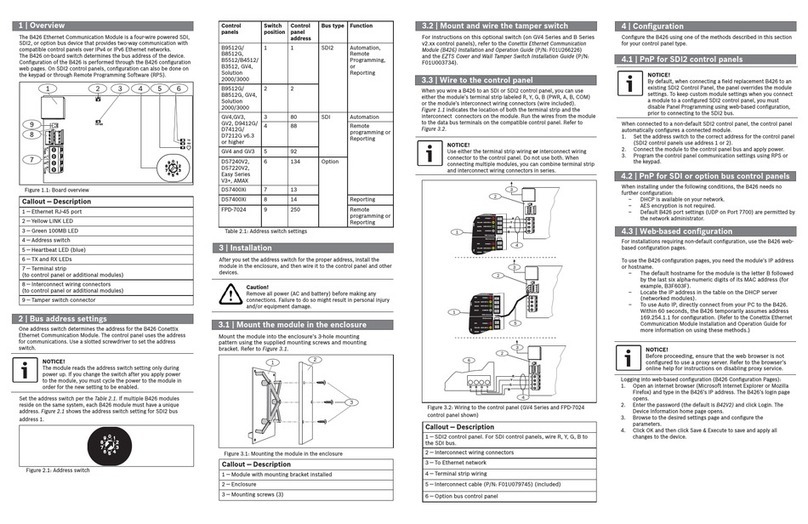
2 | Bus address settings
3 | Installation
After you set the address switch for the proper address, install the
module in the enclosure, and then wire it to the control panel and other
devices.
Caution!
Remove all power (AC and battery) before making any
connections. Failure to do so might result in personal injury
and/or equipment damage.
3.1 | Mount the module in the enclosure
Mount the module into the enclosure’s 3-hole mounting
pattern using the supplied mounting screws and mounting
bracket. Refer to Figure 3.1.
3
12
Figure 3.1: Mounting the module in the enclosure
Callout ― Description
1 ― Module with mounting bracket installed
2 ― Enclosure
3 ― Mounting screws (3)
3.3 | Wire to the control panel
When you wire a B426 to an SDI or SDI2 control panel, you can use
either the module’s terminal strip labeled R, Y, G, B (PWR, A, B, COM)
or the module’s interconnect wiring connectors (wire included).
Figure 1.1 indicates the location of both the terminal strip and the
interconnect connectors on the module. Run the wires from the module
to the data bus terminals on the compatible control panel. Refer to
Figure 3.2.
NOTICE!
Use either the terminal strip wiring or interconnect wiring
connector to the control panel. Do not use both. When
connecting multiple modules, you can combine terminal strip
and interconnect wiring connectors in series.
1 | Overview 3.2 | Mount and wire the tamper switch
For instructions on this optional switch (on GV4 Series and B Series
v2.xx control panels), refer to the
Conettix Ethernet Communication
Module (B426) Installation and Operation Guide (P/N: F01U266226)
and the
EZTS Cover and Wall Tamper Switch Installation Guide (P/N:
F01U003734).
Set the address switch per the Table 2.1. If multiple B426 modules
reside on the same system, each B426 module must have a unique
address. Figure 2.1 shows the address switch setting for SDI2 bus
address 1.
Callout ― Description
1 ― SDI2 control panel. For SDI control panels, wire R, Y, G, B to
the SDI bus.
2 ― Interconnect wiring connectors
3 ― To Ethernet network
4 ― Terminal strip wiring
5 ― Interconnect cable (P/N: F01U079745) (included)
6 ― Option bus control panel
Figure 3.2: Wiring to the control panel (GV4 Series and FPD-7024
4 | Configuration
Configure the B426 using one of the methods described in this section
for your control panel type.
NOTICE!
By default, when connecting a field replacement B426 to an
existing SDI2 or option bus control panel, the panel overrides
the module settings. To keep custom module settings when
you connect a module to a configured control panel, you must
disable Panel Programming using web-based configuration,
prior to connecting to the SDI2 or option bus.
When connected to a non-default SDI2 or option bus control panel, the
control panel automatically configures a connected module.
1. Set the address switch to the correct address for the control panel
(SDI2 control panels use address 1 or 2, option control panels use
addresses 134 or 250).
2. Connect the module to the control panel bus and apply power.
3. Program the control panel communication settings using RPS for
SDI2 control panel, A-Link for option control panel, or the keypad.
NOTICE!
Before proceeding, ensure that the web browser is not
configured to use a proxy server. Refer to the browser’s
online help for instructions on disabling proxy service.
4.1 | PnP for SDI2 or option bus control panel
4.2 | PnP for SDI or option bus control panels
When installing under the following conditions, the B426 needs no
further configuration:
– DHCP is available on your network.
– AES encryption is not required.
– Default B426 port settings (UDP on Port 7700) are permitted by
the network administrator.
4.3 | Web-based configuration
For installations requiring non-default configuration, use the B426 web-
based configuration pages.
To use the B426 configuration pages, you need the module’s IP address
or hostname.
– The default hostname for the module is the letter B followed
by the last six alpha-numeric digits of its MAC address (for
example, B3F603F).
– Locate the IP address in the table on the DHCP server
(networked modules).
– To use Auto IP, directly connect from your PC to the B426.
Within 60 seconds, the B426 temporarily assumes address
169.254.1.1 for configuration. (
Refer to the Conettix Ethernet
Communication Module Installation and Operation Guide
for
more information on using these methods.)
Logging into web-based configuration (B426 Configuration Pages):
1. Open an internet browser (Microsoft Internet Explorer or Mozilla
Firefox) and type in the B426’s IP address. The B426’s login page
opens.
2. Enter the password (the default is B42V2) and click Login. The
Device Information home page opens.
3. Browse to the desired settings page and configure the
parameters.
4. Click OK and then click Save & Execute to save and apply all
changes to the device.
control panel shown)
NOTICE!
Option bus control panels support AMAX 2100/ 3000/ 4000
firmware version v1.5 or higher only.
NOTICE!
The module reads the address switch setting only during
power up. If you change the switch after you apply power
to the module, you must cycle the power to the module in
order for the new setting to be enabled.
One address switch determines the address for the B426 Conettix
Ethernet Communication Module. The control panel uses the address
for communications. Use a slotted screwdriver to set the address
switch.
Figure 2.1: Address switch
Table 2.1: Address switch settings
Control
panels
Switch
position
Control
panel
address
Bus type Function
B9512G/
B8512G,
B6512/B5512/
B4512/B3512,
GV4, Solution
2000/3000
1 1 SDI2 Automation,
Remote
Programming,
or
Reporting
B9512G/
B8512G, GV4,
Solution,
2000/3000
22
GV4,GV3,
GV2, D9412G/
D7412G/
D7212G v6.3
or higher
3 80 SDI Automation
4 88 Remote
programming or
Reporting
GV4 and GV3 5 92
FPD-7024
v1.06+,
DS7240V2,
DS7220V2,
Easy Series,
V3+, CMS
Series, AMAX
Series
6 134 Option
DS7400Xi 7 13
DS7400Xi 8 14 Reporting
FPD-7024,
CMS Series,
AMAX Series
9 250 Remote
programming or
Reporting
The B426 Ethernet Communication Module is a four-wire powered SDI,
SDI2, or option bus device that provides two-way communication with
compatible control panels over IPv4 or IPv6 Ethernet networks.
The B426 on-board switch determines the bus address of the device.
Configuration of the B426 is performed through the B426 configuration
web pages. On SDI2 control panels, configuration can also be done on
the keypad or through Remote Programming Software (RPS).
Figure 1.1: Board overview
Callout ― Description
1 ― Ethernet RJ-45 port
2 ― Yellow LINK LED
3 ― Green 100MB LED
4 ― Address switch
5 ― Heartbeat LED (blue)
6 ― TX and RX LEDs
7 ― Terminal strip
(to control panel or additional modules)
8 ― Interconnect wiring connectors
(to control panel or additional modules)
9 ― Tamper switch connector
Bosch Security Systems, Inc.
130 Perinton Parkway
Fairport, NY 14450
USA
www.boschsecurity.com
© 2016 Bosch Security Systems, Inc. F.01U.291.335 | 08 | 2016.07
Copyright
This document is the intellectual property of Bosch Security Systems, Inc. and is protected by copyright. All rights reserved.
Trademarks
All hardware and software product names used in this document are likely to be registered trademarks and must be treated accordingly.
Bosch Security Systems, Inc. product manufacturing dates
Use the serial number located on the product label and refer to the Bosch Security Systems, Inc. website at
http://www.boschsecurity.com/datecodes/.
14 | Certifications
Dimensions 59.5 mm x 108 mm x 16 mm (2.19 in x 4.25 in x 0.629 in)
Voltage (operating) 12 VDC nominal
Current (maximum) 100 mA max
Connectors LAN/WAN: RJ-45 modular port (Ethernet)
Ethernet cable Category 5 or better unshielded twisted pair, 100 m (328 ft) max length
Interface IEEE 802.3
Data bus wire size 1.02 mm to 0.65 mm (18 AWG to 22 AWG)
Data bus wire length Maximum distance - Wire size:
150 m (500 ft) - 0.65 mm (22 AWG)
300 m (1000 ft) - 1.02 mm (18 AWG)
Web browser Microsoft Internet Explorer; Mozilla Firefox
Compatibility AMAX 2000/2100/3000/4000
B9512G/B9512G-E, B8512G/B8512G-E
B6512, B5512/B5512E, B4512/B4512E, B3512/B3512E
D9412GV4/D7412GV4/D7212GV4
D9412GV3/D7412GV3/D7212GV3
D9412GV2/D7412GV2/7212GV2
D9412G/D7412G/D7212G Version 6.3 or higher
D9412/D7412/D7212
D9112
DS7220 Version 2.10 or higher
DS7240 Version 2.10 or higher
DS7400XiV4 Version 4.10 or higher
Easy Series V3+
FPD-7024 Version 1.02 or higher
Solution 2000/3000
7 | Specifications
Bosch Sicherheitssysteme GmbH
Robert-Bosch-Ring 5
85630 Grasbrunn
Germany
5 | LED descriptions
The B426 module includes the following on-board LEDs to assist
with troubleshooting issues.
Flash pattern Function
Flashes once
every 1 sec
Normal state: Indicates normal operation state.
3 quick flashes
every 1 sec
Communication error state: Indicates a bus
communication error. The module is not
receiving commands from the control panel.
On Steady Trouble state. Indicates a trouble condition
exists.
Off LED trouble state. Module is not powered, or
some other trouble condition prohibits the
module from controlling the heartbeat LED.
Table 5.1: Heartbeat LED descriptions
Flash pattern Function
RX (Receive)
flashes
Occurs when the module receives a message
over the network connection – UPD, TCP, or
DNS.
TX (Transmit)
flashes
Occurs when the module sends a message
over the network connection – UPD, TCP, or
DNS.
Table 5.2: RX and TX LEDs descriptions
LINK (yellow)
flash pattern
100mb (green)
flash pattern
Function
Off Off No Ethernet link
On Steady Off 10 BASE-T link
Flash Off 10 BASE-T activity
On Steady On Steady 100 BASE-T link
Flash On Steady 100 BASE-T activity
Table 5.3: Ethernet LINK and 100mb LEDs descriptions
6 | Certifications
Region Certification
US UL 365 – Police Station Connected Burglar Alarm Units and Systems
UL 609 – Local Burglar Alarm Units and Systems
UL 864 – Control Units and Accessories for Fire Alarm Systems (Including NFPA 72)
UL 985 – Household Fire Warning System Units
UL 1023 – Household Burglar Alarm System Units
UL 1076 – Proprietary Burglar Alarm Units and Systems
UL 1610 – Central Station Burglar Alarm Units
FCC Part 15 Class B, NIST FIPS-197 AES Certification
(IP Communications)
Canada CAN/ULC S303 – Local Burglar Alarm Units and Systems
CAN/ULC S304 – Signal Receiving Centre and Premise Alarm Control Units
CAN/ULC S559 – Fire Signal Receiving Centres and Systems
ULC-ORD C1023 – Household Burglar Alarm System Units
ULC-ORD C1076 – Proprietary Burglar Alarm Units and
Systems
ICES-003 – Digital Apparatus
EU EN 50130-4, EN 61000-6-3, EN 60950
Australia C-Tick
Table 5.4: Trouble conditions indicated through LEDs
Condition Heartbeat Transmit
(TX)
Receive
(RX)
Network cable
disconnected
On Steady Off 1 quick flash,
repeating
Obtaining an IP
address
On Steady Off 2 quick flashes,
repeating
Low bus
voltage
On Steady Off 3 quick flashes,
repeating
Internal failure On Steady On Steady On Steady
For complete installation, configuration, and testing instructions,
refer to the Conettix Ethernet Communication Module (B426) Installation
and Operation Guide provided on the supplied CD-ROM.
en Quick Start Guide
Conettix Ethernet Communication
Module
B426

Other manuals for B426

6

Other Bosch Control Unit manuals

Bosch MAP Control Center IUI-MAP0001-2 User manual

Bosch

Bosch MAP Control Center IUI-MAP0001-2 User manual

Bosch D192G User manual

Bosch

Bosch D192G User manual

Bosch FLM-420-O2-D User manual

Bosch

Bosch FLM-420-O2-D User manual

Bosch MS 6 User manual

Bosch

Bosch MS 6 User manual

Bosch ICP-COM-IF User manual

Bosch

Bosch ICP-COM-IF User manual

Bosch CM751B How to use

Bosch

Bosch CM751B How to use

Bosch rexroth DB20K.1X E Series User manual

Bosch

Bosch rexroth DB20K.1X E Series User manual

Bosch CL400 User manual

Bosch

Bosch CL400 User manual

Bosch Rexroth IndraControl VCP 02.2 Technical manual

Bosch

Bosch Rexroth IndraControl VCP 02.2 Technical manual

Bosch Control 8311 User manual

Bosch

Bosch Control 8311 User manual

Bosch Rexroth DB 52 3X E Series User manual

Bosch

Bosch Rexroth DB 52 3X E Series User manual

Bosch OMNEO OM-1 User manual

Bosch

Bosch OMNEO OM-1 User manual

Bosch FLM-420-I2-E User manual

Bosch

Bosch FLM-420-I2-E User manual

Bosch Sensortec Application Board 3.0 User manual

Bosch

Bosch Sensortec Application Board 3.0 User manual

Bosch Rexroth IM24V User manual

Bosch

Bosch Rexroth IM24V User manual

Bosch POPEX B299 User manual

Bosch

Bosch POPEX B299 User manual

Bosch Rexroth IndraControl XFE 01.1 Series User manual

Bosch

Bosch Rexroth IndraControl XFE 01.1 Series User manual

Bosch Rexroth SB24/34 User manual

Bosch

Bosch Rexroth SB24/34 User manual

Bosch ICP-MAP5000-2 User manual

Bosch

Bosch ICP-MAP5000-2 User manual

Bosch Conettix C900V2 User manual

Bosch

Bosch Conettix C900V2 User manual

Bosch Rexroth M-2SMM6 SO711 Series User manual

Bosch

Bosch Rexroth M-2SMM6 SO711 Series User manual

Bosch Rexroth IndraControl VCP 25.2 Technical manual

Bosch

Bosch Rexroth IndraControl VCP 25.2 Technical manual

Bosch FLM-320-EOL4W-S User manual

Bosch

Bosch FLM-320-EOL4W-S User manual

Bosch GCY 30-4 Professional User manual

Bosch

Bosch GCY 30-4 Professional User manual

Popular Control Unit manuals by other brands

ABB Busch-priOn Series Technical reference manual

ABB

ABB Busch-priOn Series Technical reference manual

Holybro 11048 User manual & installation guide

Holybro

Holybro 11048 User manual & installation guide

Festo CPX Series Brief description

Festo

Festo CPX Series Brief description

Carlisle BINKS 84-601 Service manual

Carlisle

Carlisle BINKS 84-601 Service manual

Emerson Keystone EPI2 Installation, operation and maintenance manual

Emerson

Emerson Keystone EPI2 Installation, operation and maintenance manual

Honeywell SM110 Installation instruction

Honeywell

Honeywell SM110 Installation instruction

Sporlan Parker S3C Startup guide

Sporlan

Sporlan Parker S3C Startup guide

dji RONIN-SC BG18 GRIP Product information

dji

dji RONIN-SC BG18 GRIP Product information

National Instruments PXIe-5693 Getting started guide

National Instruments

National Instruments PXIe-5693 Getting started guide

Burkert AirLINE 8652 quick start

Burkert

Burkert AirLINE 8652 quick start

Icop VDX2-6518-E user manual

Icop

Icop VDX2-6518-E user manual

Innophase Talaria TWO EVB-A user guide

Innophase

Innophase Talaria TWO EVB-A user guide

Pentair BAA A390-D.03 Select operating instructions

Pentair

Pentair BAA A390-D.03 Select operating instructions

Armstrong 3750 Installation and operating instructions

Armstrong

Armstrong 3750 Installation and operating instructions

V2 Easy 3 manual

V2

V2 Easy 3 manual

Honeywell VC Series installation instructions

Honeywell

Honeywell VC Series installation instructions

Himax X-DO 24 02 manual

Himax

Himax X-DO 24 02 manual

RED CONNECT MODULE Operation guide

RED

RED CONNECT MODULE Operation guide

manuals.online logo
manuals.online logoBrands
  • About & Mission
  • Contact us
  • Privacy Policy
  • Terms and Conditions

Copyright 2025 Manuals.Online. All Rights Reserved.