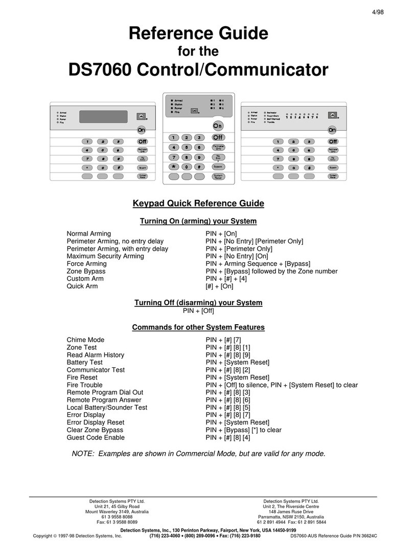
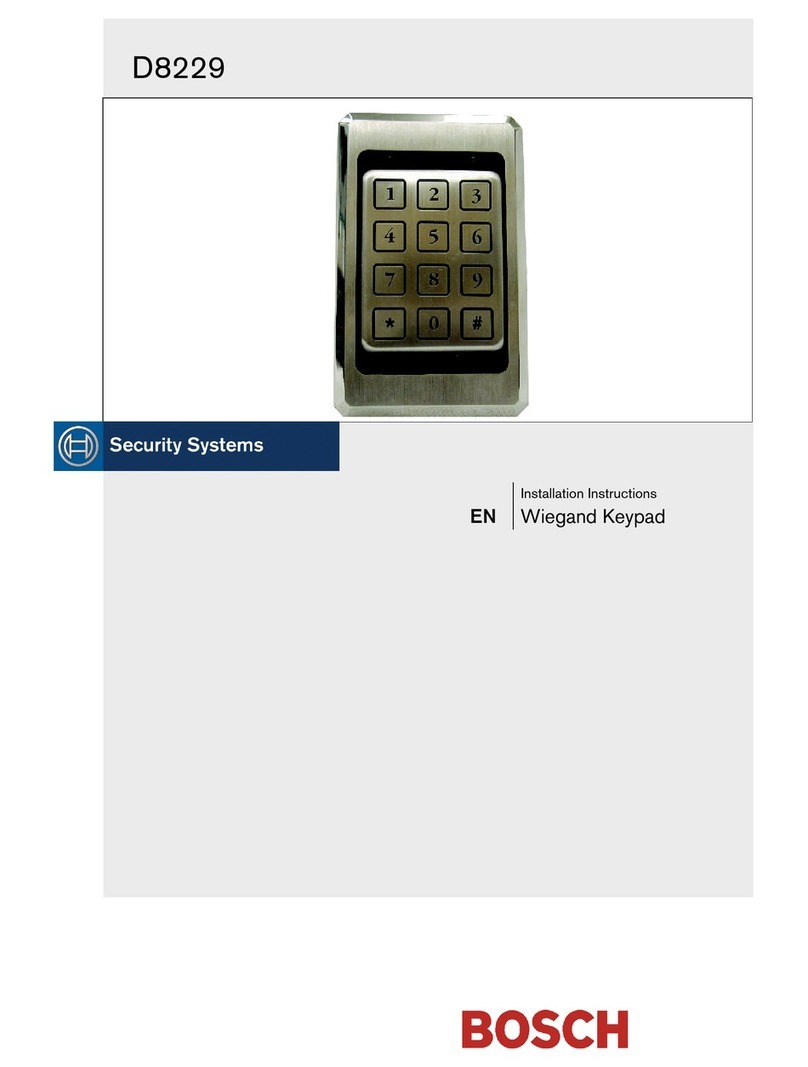
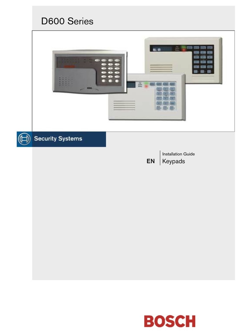
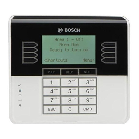
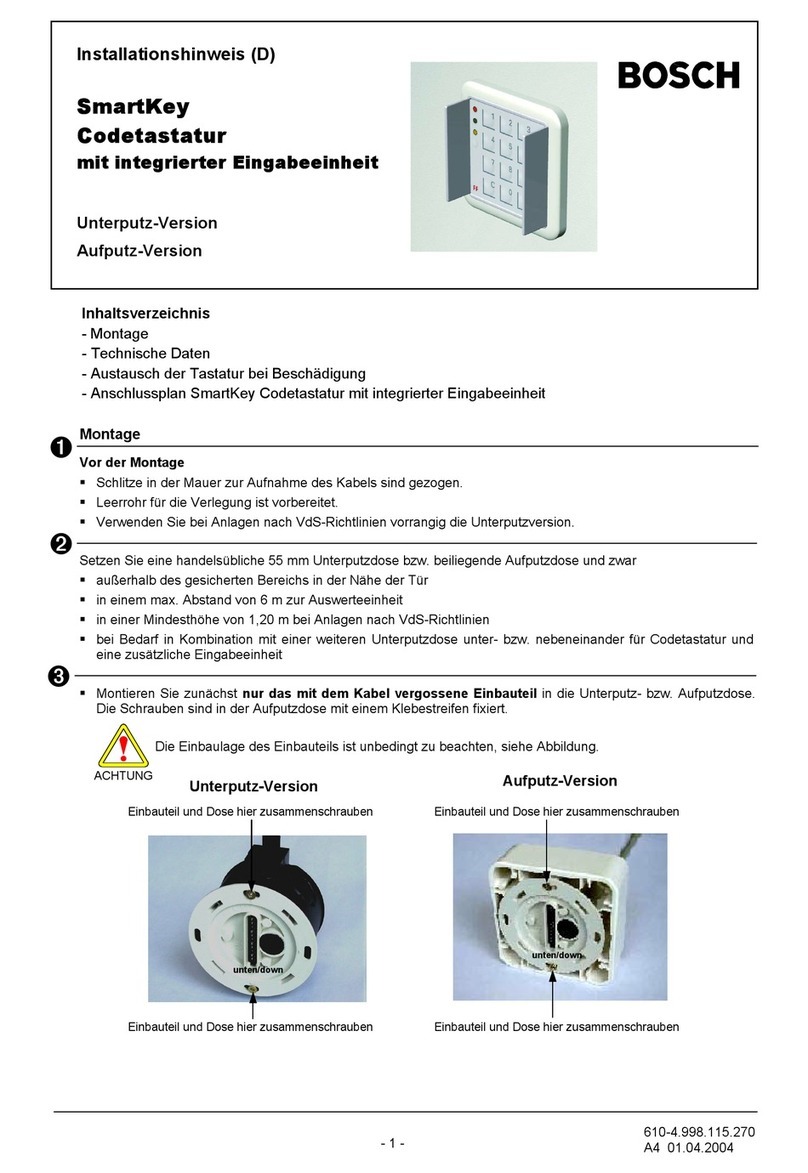
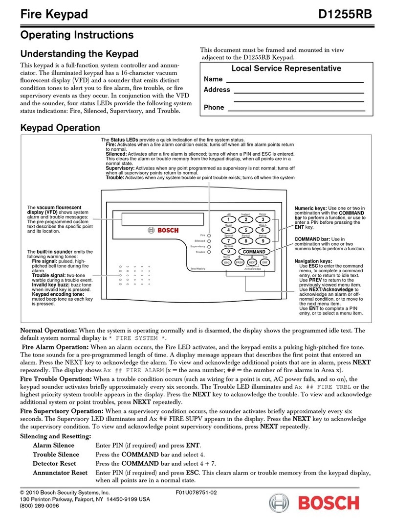
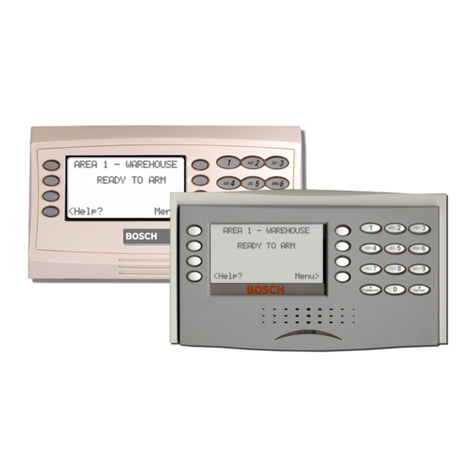
Bosch IUI-UEZ-BE1000s User manual

IUI-UEZ-BE1000s Intrusion Keypad
Manuel d'utilisation
IUI-UEZ-BE1000s
Intrusion
FR
Gebruiksaanwijzing
IUI-UEZ-BE1000s
Inbraakdetectie
NL
Operating manual
IUI-UEZ-BE1000s
Intrusion
Bedienungsanleitung
IUI-UEZ-BE1000s
Notruf
EN
DE

- 2 -
Introduction and safety instructions..............3
Display/control elements
Explanation of message display ........................4
Explanation of keys............................................5
Message display/processing ..........................6
Querying statuses
Querying areas and triggering statuses.............7
Querying internal program statuses...................8
Time-controlled activation
Time-controlled arming ......................................9
Time-controlled disarming................................10
Code mode
Starting and ending code mode.......................11
Starting and ending code mode with
messages present............................................12
Operation in the menu
Calling up and ending functions.......................13
Switching internal programs on and off............14
Resetting the control panel..............................15
Resetting internal messages............................15
Display test ......................................................16
Querying areas and ignoring
detector zones and faults.................................17
Isolating detector zones...................................18
Isolating a detector in a detector zone.............19
Walktest...........................................................20
Notes ..............................................................21
Table of Contents

- 3 -
Introduction to operation
The remote keypad can only be operated by
trained personnel.
For safety reasons and to prevent faulty op-
eration, the authorization code for operating
the system should only be provided to these
people.
Under certain conditions, the keypad is inac-
tive, i.e. inoperable
Detection area is armed. The keypad has
been allocated to the armed detection area.
Detection area is armed. The keypad has
been programmed to "dark when armed".
Holdup alarm in the system. The keypad
has been programmed to "dark if holdup".
What will this operating manual tell you
This manual contains all information required
for interpreting the message display and op-
erating the keypad.
What this operating manual will not tell
you
The operating manual does do not provide
any information regarding general or special-
ized technical/safety knowledge.
Therefore: Please ensure that you are famil-
iar with all safety/technical procedures and
guidelines in your area (e.g. what to do in the
event of an alarm, application plans, alarm
organization, etc.).
Notes regarding cleaning
When cleaning the surface of the keypad,
particularly the user interface and display
unit, ensure that no corrosive or abrasive
cleansers are used and that no fluid pene-
trates into the inside of the unit.
Introduction and safet
y
instructions

- 4 -
Explanation of message display
Display for operation (green LED).
The display lights up when the unit is
ready for operation.
Cumulative display for alarms (red LED).
The display lights up in the event of an ex-
ternal or internal alarm, a pre-alarm, or a
fault with external alarm signaling.
The corresponding alarm is saved and in-
dicated by the buzzer.
General display for faults (yellow LED).
The display lights up for all types of faults.
The corresponding fault message is saved
and indicated by the buzzer. If the type of
fault cannot be reset by the authorized
user, 24-hour service must be informed.
Display (LCD): The display consists of
2 lines with 16 characters. All pending mes-
sages as well as the notes for operation are
displayed in the menu in plain text. If the key-
pad is in standby mode, i.e. there are no
messages and no functions have been called
up from the menu, then the current time, the
date, as well as access via the center vari-
able function key in the menu will appear.
Display/control elements
pNumber of the current message
qType of message
rDetector zone number
sDetector number of the detector zone
3 HO UP 0012-6
MESSAGE? DETEC.
pq r s
nNumber of messages
oType of message
03 HOLD UP
MENU
n o
15 : 13 22.11.2005
MENU
0
987
654
21 3
G H ID E F
A
B C
P Q RM N OJ K L
S T U Y Z
ENTER
./:
STOP
V W X

- 5 -
Explanation of keys
Variable function keys
The variable function keys can be
used to call up the functions dis-
played via these keys. The text
that appears above the key in the
display provides information for
operating the corresponding vari-
able function key; for example:
- The left variable key calls up the next mes-
sage.
- The center variable key displays the help
text for 3 seconds.
- The right variable key calls up the next de-
tector of the detector zone.
Information regarding the variable function
keys for operating the functions in the menu:
Scroll forward through the functions in
the menu using the right variable function
key.
Scroll backwards through the functions
in the menu using the left variable function
key.
Function keys
Enter digits:
If number entries are required (e.g. inputting
the operator code), these entries can be
made at the position where the cursor is lo-
cated.
Confirm input:
Press the "ENTER" key:
- After inputting the digits.
- To call up the functions in the menu.
Return / Stop:
The "STOP" key causes a return by one level
or cancellation of the function started.
Switch off buzzer:
The buzzer will sound in the event of alarm or
fault messages. The buzzer can be switched
off using the "Buzzer off" key.
.................................
?
Display/control elements
)Variable function keys
3 HO UP 0012-6
MESSAGE ? DETEC
Display
ENTER
STOP
A B C
1
Important
info

- 6 -
Description
Example: there are a total of 3 messages (de-
tector zones) pending that are message type
e.g. "INTRUSION". If multiple message types
are pending, they are displayed according to
their priority.
Procedure
1.Call up the next message type. Press the
right key.
The right key can be used to call up
additional message types (e.g. "FAULT").
2.Call up the message for the message type
selected. Press the "ENTER" key.
The chronologically first message (1) will
be displayed along with the detector zone
(no. 0001) and the detector (no. 02).
3.Call up additional messages. Press the left
key.
The messages (detector zones) for the
message type selected can be called up
with the left key. The messages are
displayed consecutively according to their
chronological order e.g. detector zone
(no. 0033) along with the detector (no. 07).
4.Call up additional detectors. Press the right
key.
The next triggered detector (no. 14) in the
detector zone (no. 0033) will be displayed
in the first line.
5.Call up additional information. Press the
center key.
The additional information (e.g. staircase)
will be displayed in plain text for approxi-
mately 3 seconds. For units networked us-
ing SRT, the unit number is displayed for
an additional 3 seconds. The display then
returns to the previous display.
1 FAULT 0001-02
STAIRCASE
2 FAULT 0033-14
MESSAGE ? DETEC
03 INTRUS. EXT
MENU
2 FAULT 0033-07
MESSAGE ? DETEC
02 FAULT
MENU
1 FAULT 0001-02
MESSAGE ? DETEC
Message display/processing

- 7 -
Querying areas and triggering
statuses
Description
The status of ON/OFF areas (armed/dis-
armed) and their triggering of detectors can
be displayed on the display. For example, in
order to properly arm the system, all doors
and windows must be in normal condition
(closed). This function can be used, for ex-
ample, to locate corresponding detectors and
detector zones in the system. Example – dis-
play:
Procedure
1.Start a query. Press the center
"menu" key.
The query display will appear.
2.Call up areas. Press the left key.
The first area and its status will be dis-
played.
3.Call up additional areas. Press the right
key.
The right key can be used to call up
additional areas consecutively. After the
last area, "AREA 01" reappears in the dis-
play. If the area is not ready for arming,
"NARM" (reasons for "not ready for arm-
ing") appears in the display.
4.Call up an area's triggering. Press the cen-
ter key.
The reasons for "not ready for arming" will
be displayed.
5.Call up an area's additional triggering.
Press the right key.
The right key can be used to call up
the area's additional triggering consecu-
tively. After the last triggering, the first trig-
gering reappears in the display.
6.Call up additional information. Press the
center key.
Additional information for the triggering will
be displayed for approximately 3 seconds.
7.Return. Press the "STOP" key twice.
The "STOP" key causes a return by one
level. The query will be ended.
15 : 13 22.11.2005
MENU
ID:0 CO:¾¾¾¾¾¾
A
REA PROG.
0005 - 13 = TRIGGE
Window room 6
0005 - 17 = TRIGGE
?
0005 - 13 = TRIGGE
?
AREA 01 = OFF
NARM
ID:0 CO:¾¾¾¾¾¾
AREA PROG.
AREA 02 = OFF
NARM
Querying statuses

- 8 -
Querying internal program statuses
Description
Example – display:
Procedure
1.Start a query. Press the center
"menu" key.
The query for the internal program will be
started and displayed.
2.Call up internal programs. Press the right
key.
The first internal program and its status
(ON/OFF) will be displayed
3.Call up additional internal programs. Press
the right key.
By pressing the right key, additional
internal programs can be called up con-
secutively. The status of internal program
02 (ON/OFF) will be displayed. After the
last internal program and pressing the right
key, internal program 1 reappears in
the display.
4.End the query. Press the "STOP" key
This action ends the query. If you press the
"STOP" key is again, the standby picture
will appear in the display.
15 : 13 22.11.2005
MENU ID:0 CO:¾¾¾¾¾¾
A
REA PROG.
INT-PR 01 = ON
ID:0 CO:¾¾¾¾¾¾
AREA PROG.
INT-PR 02 = ON
Querying statuses

- 9 -
Time-controlled arming
Description
The exit delay time must be entered by the
safety company in charge. Not in compliance
with VdS.
There are ______ seconds available for exit-
ing the premises before the system is armed.
Procedure
1.Call up the input field for time-controlled
arming. Press the center key.
The input field for the time-controlled arm-
ing code will be displayed.
2.Start time-controlled arming.
Enter ID (1 to 3 digits) for ID 7, e.g. enter
007. Enter code (0 to 6 digits), e.g. 123123;
time-controlled arming starts automatically
after entry of the digits. Only press the
"ENTER" key if the code is < 6 digits.
3.Time-controlled arming is activated.
The delay time has started. The buzzer will
sound during the exit delay time. The room
must be exited within the programmed time
of ... seconds.
The left key can be used to cancel the
arming procedure if needed.
4.Time-controlled arming is active.
After the door is closed, the system is
armed, which is indicated by a buzzer
sound of 3 seconds. The following mes-
sage will appear on the display.
15 : 13 22.11.2005
MENU
AREA
A
RMED
ID: 007 CO:_ _ _ _ _ _
AREA PROG.
ID:0 CO:¾¾¾¾¾¾
AREA PROG.
ARMED IN . . . . . s
CANCEL
Time-controlled activation

- 10 -
Time-controlled disarming
Description
The entry delay time must be entered by the
safety company in charge. Not in compliance
with VdS.
There are ______ seconds available to enter
the premises and disarm the system.
Procedure
1.The buzzer sounds when the door group is
triggered.
2.Call up the input field for time-controlled
disarming. Press the "menu" key.
The input field for the time-controlled dis-
arming code will be displayed.
3.Enter the time-controlled disarming code.
Enter ID (1 to 3 digits) for ID 7, e.g. en-
ter 007. Enter code (0 to 6 digits), e.g.
123123; time-controlled disarming starts
automatically after entry of the six digits.
Only press the "ENTER" key if the code is
< 6 digits. There are .... seconds available.
4.Time-controlled disarming has been exe-
cuted.
After successfully disarming, the message
"AREA DISARMED" will appear in the dis-
play.
ID:0 CO:¾¾¾¾¾¾
ID: 007 CO:_ _ _ _ _ _
15 : 13 22.11.2005
MENU
AREA
DISARMED
Time-controlled activation

- 11 -
Starting and ending code mode
Description
Inputting the user code grants control au-
thorization level 1 for basic operation or con-
trol authorization level 2 for all operations.
The user code is divided up into the following
areas:
- ID (1 – 3 digits)
- Password (0 – 6 digits)
The password can be changed on the control
panel's operating panel.
Procedure
1.The standby status of the system will be
displayed.
2.Starting code input. Press the center
key.
The code input display will appear.
3.Enter the user code.
Enter ID (1 to 3 digits) for ID 2, e.g. en-
ter 002. Enter password (0 to 6 digits),
e.g. 123123
4.Start code mode.
If the user code has been entered correctly
and confirmed with the "ENTER" key with a
code of < 6 digits, the first function will be
displayed in the menu.
If no key is pressed for one minute, the
standby picture for the menu or the current
message with the highest priority is dis-
played. If no input is made for 15 minutes,
code mode ends automatically.
5.End code mode.
Call up the "STOP CODEOPERATION"
function in the menu, and confirm with the
"ENTER" key (also see chapter "Calling up
and ending functions"). The code mode will
be exited once again.
15 : 13 22.11.2005
MENU
15 : 13 22.11.2005
MENU
01: INTERN. PROG.
ID: 002 CO:_ _ _ _ _ _
AREA PROG.
ID:0 CO:¾¾¾¾¾¾
AREA PROG.
Code mode

- 12 -
Starting and ending code mode with
messages present
Description
Inputting the user code grants control au-
thorization level 1 for basic operation or con-
trol authorization level 2 for all operations.
The user code is divided up into the following
areas:
- ID (1 – 3 digits)
- Password (0 – 6 digits)
The password can be changed on the control
panel's operating panel.
Procedure
1.For example, 3 intrusion messages are
displayed.
2.Start code input. Press the center
"menu" key.
The code input display will appear.
3.Enter the user code.
Enter ID (1 to 3 digits) for ID 2, e.g. en-
ter 002. Enter password (0 to 6 digits),
e.g. 123123.
4.Start code mode.
If the user code has been entered correctly
and confirmed with the "ENTER" key for a
code of < 6 digits, any activated sirens will
be switched off and the first function will be
displayed in the menu.
5.Call up the message display in code mode
once again.
After the "STOP" key has been pressed,
the message is displayed without ending
code mode.
6.End code mode.
Call up the "STOP CODEOPERATION"
function in the menu and confirm with the
"ENTER" key. (Also see chapter "Calling
up and ending functions".) The code mode
will be exited once again.
ID: 002 CO:_ _ _ _ _ _
AREA PROG.
03 INTRUS. EXT.
Menu
03 INTRUS. EXT.
Menu
03 INTRUS. EXT
Menu
01: INTERN. PROG.
ID:0 CO:¾¾¾¾¾¾
AREA PROG.
Code mode

- 13 -
Calling up and ending functions
Description
All functions used to execute the different
tasks are described on the following pages of
these operating instructions.
Procedure
1.Start code mode (see chapter "Code
mode").
If the user code has been entered properly,
the first "Intern. prog." function of the menu
will be displayed.
2.The right key can be used to jump to
the individual functions consecutively.
If no key is pressed for 1 minute, the
standby picture for the menu is displayed.
3.Call up a function for processing.
A function, e.g. "TOTAL RESET", is called
up by pressing the "ENTER" key.
4.End code mode.
Select the "STOP CODEOPERATION"
function and confirm with the "ENTER" key.
The code mode will be exited once again.
15 : 13 22.11.2005
MENU
01: INTERN.PROG.
TOTAL RESET ?
RESET
01: INTERN. PROG.
02: TOTAL RESET
03: INTERN. RESET
04: DISPLAY TEST
05: AREAS
06: ISOLATE ZONES
07: WALKTEST
00:STOP CODEOPER
Operation in the menu

- 14 -
Switching internal programs on
and off
Procedure
1.Call up "Intern. prog." function from the
menu. See chapter "Calling up and ending
functions".
2.Call up "Internal programs".
By pressing the "ENTER", the first internal
program and its status (ON/OFF) are dis-
played.
3.Call up additional "Internal programs".
By pressing the right key, additional
internal programs can be called up con-
secutively. After the last internal program
and pressing the right key, internal
program 1 reappears in the display.
4.Switch "Internal programs" on and off.
The internal program can be switched on
or off using the center key.
5.Return
The "STOP" key causes a return by one
level. The menu will be displayed.
INT-PR 02 = OFF
ON
INT-PR 01 = OFF
ON
01: INTERN. PROG.
INT-PR 02 = OFF
ON
01: INTERN. PROG.
Operation in the menu

- 15 -
Resetting the control panel
Description
To switch the system back into standby mode
after messages have come in, the messages
must be reset. Then the system can be re-
armed. To perform a reset, the areas must be
switched to disarmed.
Procedure
1.To call up the "TOTAL RESET" function
from the menu see chapter "Calling up and
ending functions".
2.Call up "TOTAL RESET".
By pressing the "ENTER" key, the "TOTAL
RESET" display appears.
3.Execute "TOTAL RESET".
After pressing the center key, all trig-
gering for the control panel are reset.
The messages disappear from the display
as soon as all detectors are in normal con-
dition. If the message type cannot be reset
by the authorized user, 24-hour service
must be informed.
Resetting internal messages
Description
All triggered internal messages are reset.
Procedure
1.To call up the "INTERN. RESET" function
from the menu, see chapter "Calling up and
ending functions".
2.Call up "INTERN. RESET".
By pressing the "ENTER" key, the "Internal
reset" display appears.
3.Execute "INTERN RESET".
By pressing the center key, all trig-
gered internal messages are reset.
The corresponding message type is de-
leted in the display as soon as all reset de-
tectors are restored to normal condition.
INTERN. RESET ?
RESET
03: INTERN. RESET
03: INTERN. RESET
TOTAL RESET ?
RESET
02: TOTAL RESET
02: TOTAL RESET
Operation in the menu

- 16 -
Display test
Description
The LEDs, the display, and the buzzer for the
keypad are checked that they function cor-
rectly (including any external buzzers that are
activated).
Procedure
1.To call up the "DISPLAY TEST" function
from the menu, see chapter "Calling up and
ending functions".
2.Execute "DISPLAY TEST".
By pressing the "ENTER" key, the LED`s,
the display, and the buzzer of the keypad
are checked that they function correctly.
The display test ends automatically after
3 seconds.
**********************************
**********************************
**********************************
04: DISPLAY TEST
Operation in the menu

- 17 -
Querying areas and ignoring detector
zones and faults
Description
If it is not possible to arm the system, the de-
tector that was triggered can be removed
from monitoring (Ignore). Not in compliance
with VdS. Notify 24-hour service after the sys-
tem is disarmed.
Procedure
1.To call up the "AREAS" function from the
menu, see chapter "Calling up and ending
functions".
2.Call up "AREAS".
By pressing the "ENTER" key, the first de-
tection area is displayed. If the area is not
ready for arming, "NARM" appears in the
display for the center key to call up
NARM reasons (reasons for "Not ready for
arming").
3.Call up additional "AREAS".
By pressing the right key, additional
areas can be called up consecutively. After
the last area, "AREA 1" reappears in the
display.
4.Calling up NARM reasons. The center
key is used to display the NARM reasons
(reasons for "Not ready for arming").
5.Execute one of the 3 operational steps:
Ignore detectors zones and faults.
If it is not possible to arm the system, a
maximum of one "triggered detector
zone", "Network fault", or "NVU fault" can
be removed from monitoring (Ignore) by
pressing the left key. Notify 24-hour
service after the system is disarmed.
Call up additional information.
By pressing the center key, addi-
tional information for the displayed trig-
gering will be shown for approximately
3 seconds.
Call up additional triggering.
By pressing the right key, additional
reasons for failure to arm the area will be
displayed. After the last triggering, the
first triggering reappears in the display.
6.The "STOP" key causes a return by one
level.
7.The "STOP" key causes a return by one
level. The menu will be displayed.
AREA 02 = ON
NARM
05: AREAS
0010 - 05 = TRIGGE
IGNORE ?
0005 - 13 = TRIGGE
IGNORE ?
AREA 01 = OFF
NARM
05: AREAS
AREA 02 = OFF
NARM
Operation in the menu

- 18 -
Isolating detector zones
Description
This function makes it possible to isolate one
detector zone or multiple detector zones be-
fore the system is armed. Areas of disarmed
detector zones can be entered if the system
is armed, without an alarm being triggered.
Not in compliance with VdS.
Procedure
1.To call up "ISOLATE ZONES" from the
menu, see chapter "Calling up and ending
functions".
2.Call up detector zone.
By pressing the "ENTER" key, the first de-
tector zone that can be isolated and its
status (ON/OFF) will be displayed.
3.Call up additional detector zones.
By scrolling with the keys or by direct
entry of the address using the number pad,
additional detectors zones that can be iso-
lated are displayed.
4.Initiate isolation procedure.
Once the detector zone to be isolated has
been called up, the isolation procedure is
initiated by pressing the center key.
5.Isolate detector zone.
To isolated detector zone 2, press the right
key. After isolation has been com-
pleted, the new status of the detector zone
(= OFF) will be displayed.
6.Reset.
The "STOP" key causes a return by one
level. The menu will be displayed.
06: ISOLATE ZONES
ZO 0002 = OFF
v
ZO 0001 = ON
v
06: ISOLATE ZONES
ZO 0002 = ON
v
ZO 0002 = ON
ON v OFF
Operation in the menu

- 19 -
Isolating a detector in a detector zone
Description
This function can be used to isolate individual
detectors before the system is armed. Areas
with isolated detector zones can be entered if
the system is armed, without an alarm being
triggered. Not in compliance with VdS.
Procedure
1.To call up "ISOLATE ZONES" from the
menu, see chapter "Calling up and ending
functions".
2.Call up detector zone.
By pressing the "ENTER" key, the first de-
tector zone that can be isolated and its
status (ON/OFF) will be displayed.
3.Call up additional detector zones.
By scrolling with the keys or by direct
entry of the address using the number pad,
additional detectors zones that can be iso-
lated are displayed.
4.Search for "Detector".
Press center key 2 x to enable the
display of individual detectors.
5.Call up detector.
By pressing the right key, the first de-
tector from the selected detector zone will
be displayed.
6.Call up additional detectors.
By scrolling with the right key, a par-
ticular detector from this detector zone can
be selected and displayed.
7.Initiate isolation procedure.
Once the detector zone to be switched off
has been called up, the isolation procedure
is initiated by pressing the center key.
8.Isolate detector.
Press the right key to isolate the de-
tector. After isolation has been completed,
the new status of the detector (=OFF) will
be displayed.
9.Reset.
Press "STOP" key 2 x. The "STOP" key
causes a return by one level. The menu will
be displayed.
ZO 0002 = ON
v
ZO 0001 = ON
v
0002 – 13 = OFF
v
0002 – 13 = ON
ON v OFF
0002 – 13 = ON
v
ZO 0002 = ON
? v DETEC
06: ISOLATE ZONES
0002 – 01 = ON
v
06: ISOLATE ZONES
Operation in the menu

- 20 -
Walktest
Description
This function can be used to check the sys-
tem's detectors via a walktest. Any stored
messages from detector cover can be reset
using this function. The walktest is done with
the detection areas in a disarmed status.
Triggering of the detector is indicated by the
detector's red LED during a walktest.
Procedure
1.To call up the "WALKTEST" function from
the menu, see chapter "Calling up and end-
ing functions".
2.Call up "WALKTEST".
By pressing the "ENTER" key, the first de-
tection area as well as its status with re-
spect to the walktest will be displayed.
3.Call up additional detection areas for a
"WALKTEST".
By pressing the right key, additional
detection areas can be called up consecu-
tively. After the last detection area, detec-
tion area 1 reappears in the display.
4.Switch on "WALKTEST".
The "WALKTEST" of the detection area is
switched on by pressing the center
key.
5.Conduct "WALKTEST".
Trigger movement alarm. A triggering of
the detector is indicated by the detector's
red LED.
6.Switch off "WALKTEST".
The "WALKTEST" for the detection area is
switched off by pressing the center
key.
7.Return.
The "STOP" key causes a return by one
level. The menu will be displayed.
ZO 02 = OFF
ON
ZO 02 = OFF
ON
ZO 01 = OFF
ON
AREA 02 = MNSTB
OFF
07: WALKTEST
07: WALKTEST
Operation in the menu
Table of contents
Languages:
Other Bosch Keypad manuals

Bosch
Bosch FMR-5000 User manual

Bosch
Bosch D7212G Quick start guide

Bosch
Bosch D621 Series User manual

Bosch
Bosch B942 User manual

Bosch
Bosch FMR-7036 User manual

Bosch
Bosch B920 User manual

Bosch
Bosch D1260 Series User manual
Bosch
Bosch RF3341 User manual

Bosch
Bosch Security System User manual

Bosch
Bosch B930 User manual

Bosch
Bosch SOLUTION 3000 Instruction manual

Bosch
Bosch D623 Series User manual

Bosch
Bosch DS7446KP User manual

Bosch
Bosch D220ATD User manual

Bosch
Bosch VIDEOJET decoder 3000 Instruction manual

Bosch
Bosch D621 Series User manual
Bosch
Bosch AMAX 2100 User manual

Bosch
Bosch B942W User manual

Bosch
Bosch AVENAR 8000 User manual

Bosch
Bosch D1265 User manual