Bosch PFS 105 User manual

Robert Bosch GmbH
Power Tools Division
70745 Leinfelden-Echterdingen
Germany
www.bosch-pt.com
1 609 929 Y14 (2011.08) PS / 194 UNI
PFS 105 E
de Originalbetriebsanleitung
en Original instructions
fr Notice originale
es Manual original
pt Manual original
it Istruzioni originali
nl Oorspronkelijke
gebruiksaanwijzing
da Original brugsanvisning
sv Bruksanvisning i original
no Original driftsinstruks
fi Alkuperäiset ohjeet
el Ðñùôüôõðï ïäçãéþí ÷ñÞóçò
tr Orijinal işletme talimat
pl Instrukcja oryginalna
cs Původní návod k používání
sk Pôvodný návod na použitie
hu Eredeti használati utasítás
ru Îðèãèíàëüíîå ðóêîâîäñòâî ïî
ýêñïëóàòàöèè
uk Îðèã³íàëüíà ³íñòðóêö³ÿ ç
åêñïëóàòàö³¿
ro Instrucţiuni originale
bg Îðèãèíàëíà èíñòðóêöèÿ
sr Originalno uputstvo za rad
sl Izvirna navodila
hr Originalne upute za rad
et Algupärane kasutusjuhend
lv Instrukcijas oriģinālvalodā
lt Originali instrukcija
OBJ_BUCH-420-002.book Page 1 Tuesday, August 23, 2011 12:08 PM

| 3
Bosch Power Tools 1 609 929 Y14 | (23.8.11)
8
16
21
20
14
9
7
13
22
18
17
34 2
1
6
5
15
19
PFS 105 E
OBJ_BUCH-420-002.book Page 3 Tuesday, August 23, 2011 12:08 PM

1 609 929 Y14 | (23.8.11) Bosch Power Tools
4|
A1 A2
C1 C2
14
10
10
10
14
6
18
1
1
2
2
B
19
OBJ_BUCH-420-002.book Page 4 Tuesday, August 23, 2011 12:08 PM

| 5
Bosch Power Tools 1 609 929 Y14 | (23.8.11)
5-15 cm
D1
E
G
F
H
D2
2
AB C
5
16
OBJ_BUCH-420-002.book Page 5 Tuesday, August 23, 2011 12:08 PM

1 609 929 Y14 | (23.8.11) Bosch Power Tools
6|
L
KI
12
1211
1123
8
10
+
800 ml
600 ml
+
21
OBJ_BUCH-420-002.book Page 6 Tuesday, August 23, 2011 12:08 PM

14 | English
1 609 929 Y14 | (23.8.11) Bosch Power Tools
Entsorgung
Sprühpistole, Elektroeinheit, ZubehörundVerpackungensol-
len einer umweltgerechten Wiederverwertung zugeführt wer-
den.
Werfen Sie Elektrowerkzeuge nicht in den Hausmüll!
Nur für EU-Länder:
Gemäß der Europäischen Richtlinie
2002/96/EG über Elektro- und Elektronik-
AltgeräteundihrerUmsetzunginnationales
Recht müssen nicht mehr gebrauchsfähige
Elektrowerkzeuge getrennt gesammelt und
einer umweltgerechten Wiederverwertung
zugeführt werden.
Änderungen vorbehalten.
English
Safety Notes
General Power Tool Safety Warnings
Read all safety warnings, instructions
including Material Safety Data Sheets
(MSDS), and container labels provided with the paints
and solvents. Failure to follow the warnings and instructions
may result in electric shock, fire and/or serious injury.
Save all warningsand instructions for future reference.
The term “power tool” in the warnings refers to your mains-
operated (corded) power tool or battery-operated (cordless)
power tool.
Workplace safety
fKeep children and bystanders away while operating a
power tool. Distractions can cause you to loose control.
Electrical Safety
fThe plugs of power tools must match the outlet. Never
modify the plug in any way. Do not use any adapter
plugswithearthed(grounded)powertools.Unmodified
plugs and matching outlets will reduce the risk of electric
shock.
fProtect the machine from rain and moisture. The pene-
trationof waterinapowertoolincreasesthe risk ofelectric
shock.
fDo not misuse the cord. Never use the cord for carry-
ing, pulling or unplugging the power tool. Keep cord
away from heat, oil, sharp edges and moving parts.
Damaged or entangled cords increase the risk of electric
shock.
fWhen operating a power tool outdoors, use an exten-
sion cord suitable for outdoor use. Use of a cord suitable
for outdoor use reduces the risk of electric shock.
fWhen operating the power tool in damp/moist environ-
ments is unavoidable, use a residual current device
(RCD).Use of a residual current device reduces the risk of
electric shock.
Personal safety
fUse safety equipment. Always wear eye protection.
Safety equipment such as dusk mask, non-skid safety
shoes, hard hat, or hearing protection used for appropri-
ate conditions will reduce personal injuries.
Use and care of the power tool
fDo not use the power tool if the switch does not turn it
on and off. Any power tool that cannot be controlled with
the switch is dangerous and must be repaired.
fStore idle power tools out of the reach of children and
do not allow persons unfamiliar with the power tool or
these instructions to operate the power tool. Power
tools are dangerous in the hands of untrained users.
fUse the power tool, accessories and application tools
etc. in accordance with these instructions, taking into
account the working conditions and the work to be per-
formed. Use of power tools for operations different from
those intended could result in a hazardous situation.
Service
fHaveyourpowertoolserviced by a qualified repair per-
son using only identical replacement parts. This will en-
sure that the safety of the power tool is maintained.
Safety Warnings for Fine-spray Systems
fKeep area clean well lit and free of paint or solvent con-
tainers, rags, and other flammable materials. Sponta-
neous combustion may occur. Fire extinguisher equip-
ment shall be present and working at all times.
fProvide for good ventilation in the spraying area and
for sufficient fresh air in the complete room. Evaporat-
ing inflammable solvents create an explosive environment.
fDo not use materials with a flashpoint below 21 °C for
spraying and cleaning. Use water-based materials,
non-volatile hydrocarbons or similar materials. Fast
evaporating solvents create an explosive environment.
fDonot sprayinthevicinintyofignitionsources,such as
static electricity sparks, open flames, pilot lights, hot
objects, engines/motors, cigarettes and sparks from
plugging in or unplugging power cords or operating
switches. Such spark sources can ignite the spraying vi-
cinity/environment.
fDo not spray any liquid of unknown hazard potential.
Unknown materials can create hazardous conditions.
fWear additional protective equipment such as appro-
priate protective gloves and protective masks or respi-
rators when spraying or handling chemicals. Wearing
protective equipment for the appropriate conditions re-
duces the exposure to hazardous substances.
WARNING
OBJ_BUCH-420-002.book Page 14 Tuesday, August 23, 2011 12:08 PM

English | 15
Bosch Power Tools 1 609 929 Y14 | (23.8.11)
fNever point the spray jet against yourself, towards oth-
er persons or animals. Keep your hands and other body
parts away from the spray jet. If the spray jet should
penetrate the skin, seek medical attention immediate-
ly from a doctor. The material being sprayed can even
penetrate the skin through a glove and be injected into
your body.
fDonottreat aninjectionasa simplecut.Ahigh-pressure
spray is able to inject toxins into the body and cause seri-
ousbodilyinjury.Intheeventthataninjectionoccurs,seek
medical attention immediately.
fBe aware of possible hazards from the spray material.
Observe the information on drums/tanks/tins as well
as manufacturer information of the spray material, in-
cluding the request to wear personal protective equip-
ment. The manufacturer's instructions are to be observed
in order to reduce the risk of fire as well as injuries caused
through toxins, carcinogens, etc.
fUse only nozzles/nozzle inserts specified by the manu-
facturer. Never spray without the nozzle protection
mounted. Use of a special nozzle insert with the corre-
sponding nozzle protection reduces the probability that a
high-pressure jet penetrates the skin and injects toxins in-
to the body.
fExercise caution whencleaningandchangingnozzlein-
serts. If the nozzle insert should become clogged dur-
ing spraying, follow the manufacturer's instructions
for switching off the system and relieving the pressure
before removing the nozzle. Fluids under high pressure
can penetrate the skin, inject toxins into the body and lead
to serious injury.
fKeep the plug of the mains cord and the trigger switch
of the spray gun clear of paint and other fluids. Never
hold the cord by its connectors to support it. Failure to
follow the instruction can lead to electric shock.
fSupervise children. This will ensure that children do not
play with the fine-spray system.
fChildren or persons that owing to their physical, senso-
ryormental limitations or to theirlackofexperienceor
knowledge, are not capable of securely operating the
fine-spray system, may only use this fine-spray system
under supervision or after having been instructed by a
responsible person. Otherwise, there is danger of operat-
ing errors and injuries.
Products sold in GB only: Your product is fitted with an
BS 1363/A approved electric plug with internal fuse (ASTA
approved to BS 1362).
If the plug is not suitable for your socket outlets, it should be
cut off and an appropriate plug fitted in its place by an author-
ised customer service agent. The replacement plug should
have the same fuse rating as the original plug.
The severed plug must be disposed of to avoid a possible
shock hazard and should never be inserted into a mains sock-
et elsewhere.
Productssold in AUSand NZonly: Use a residual current de-
vice (RCD) with a rated residual current of 30 mA or less.
Product Description and
Specifications
Read all safety warnings and all instruc-
tions. Failure to follow the warnings and in-
structions may result in electric shock, fire
and/or serious injury.
Intended Use
The power tool is intended for atomising solvent-based and
water-dilutable paints, finishes, primers, clear finishes, auto-
motive finishes, staining sealers, wood sealer-preservatives,
plant protectives, oil and disinfection agents.
The power tool is not suitable for spraying dispersions and la-
tex paint, caustic solutions, acidic coating materials, coating
materials with granules or solids as well as spray and drip-im-
peding materials.
Product Features
The numbering of the components shown refers to the repre-
sentation of the power tool on the graphic pages.
1Spraygun
2Air cap
3Union nut
4Mark for SDS connection
5Thumbwheel for spraying capacity
6Hose port (spray gun)
7Handle extension (only for 800 ml container)
8Container for spray material, 800 ml
Container for spray material, 600 ml*
9Trigger switch
10 Suction tube with container seal
green: for 800 ml container
white: for 600 ml container*
11 Nozzle
12 Nozzle seal
13 Air hose
14 SDS connector
15 Base unit
16 Control knob for On/Off and air-flow control
17 Set-down port for spray gun
18 Hose connection (base unit)
19 Handle
20 Accessory compartment
21 Air filter cover
22 Measuring cup
*Accessories shown or described are not part of the standard de-
livery scope of the product. A complete overview of accessories
can be found in our accessories program.
OBJ_BUCH-420-002.book Page 15 Tuesday, August 23, 2011 12:08 PM

16 | English
1 609 929 Y14 | (23.8.11) Bosch Power Tools
Technical Data
Noise/Vibration Information
Measured sound values determined according to EN 60745.
Typically the A-weighted sound pressure level of the product
is 74 dB(A). Uncertainty K=3 dB.
The noise level when working can exceed 80 dB(A).
Wear hearing protection!
Vibration total values ah(triax vector sum) and uncertainty K
determined according to EN 60745:
ah< 2.5m/s2, K= 1.5 m/s2.
The vibration emission level given in this information sheet
has been measured in accordance with a standardised test
given in EN 60745 and may be used to compare one tool with
another. It may be used for a preliminary assessment of expo-
sure.
The declared vibration emission level represents the main ap-
plications of the tool. However if the tool is used for different
applications,withdifferentaccessoriesorpoorlymaintained,
the vibration emission may differ. This may significantly in-
crease the exposure level over the total working period.
An estimation of thelevel of exposure to vibration should also
take into account the times when the tool is switched off or
when it is running but not actually doing the job. This may sig-
nificantly reduce the exposure level over the total working pe-
riod.
Identify additional safety measures to protect the operator
fromthe effectsofvibration suchas:maintain thetooland the
accessories, keep hands warm, organise work patterns.
Declaration of Conformity
We declare under our sole responsibility that the product de-
scribed under “Technical data” is in conformity with the fol-
lowing standards or standardization documents: EN 60335
and the directives 2011/65/EU, 2006/42/EC,
2004/108/EC including their amendments.
Technical file (2006/42/EC) at:
Robert Bosch GmbH, Dept. PT/ESC,
D-70745 Leinfelden-Echterdingen
Robert Bosch GmbH, Power Tools Division
D-70745 Leinfelden-Echterdingen
Leinfelden, 22.08.2011
Assembly
fBefore any work on the machine itself, pull the mains
plug.
Connecting the Air hose (see figures A1 –A2)
– Take the air hose 13 out of the accessory compartment
20.
– Removetheprotectivecapsfrombothendsofthe air hose.
Connecting to the spray gun:
– Firmly insert an SDS connector 14 of the air hose in align-
ment with the arrow mark into the hose port of the spray
gun 6.
– Turn the SDS connector until the lock can be heard to
latch.
Connecting the base unit:
– Firmly insert the second SDS connector of the air hose in
alignmentwiththe arrowmarkintotheport ofthebaseunit
18.
– Turn the SDS connector until the lock can be heard to
latch.
Note:Afteruse,reattachtheprotectivehosecapsto thehose
ends.
Operation
Preparing for Operation
fSpraying on the sides of water bodies (lakes, rivers,
etc.) or neighbouring surfaces in the direct catchment
area is not permitted.
When purchasing paint, varnish and spray material, pay at-
tention to their environmental compatibility.
Preparing the Spray Surface
Note: Cover off the vicinity of the spray surface thoroughly
and generously.
The spray mist contaminates the environment. When spray-
ing in enclosures, surfaces not covered can become contami-
nated.
The spray surface must be clean, dry and grease-free.
– Roughen smooth surfaces and then remove the sanding
dust.
Fine-spray System PFS 105 E
Article number 3 603 B06 2..
Rated power input W 350
Spraying capacity g/min 150
Atomising output W 0–105
Required time for application
of paint on 5 m2min 6
Container capacity for spray
material ml 800
Length of air hose m3.4
Weight according to
EPTA-Procedure 01/2003 kg 4.9
Protection class /II
The values given are valid for a nominal voltage [U] of 230 V. For differ-
ent voltages and models for specific countries, these values can vary.
Please observe the article number on the type plate of your machine.
The trade names of the individual machines may vary.
Dr. Egbert Schneider
Senior Vice President
Engineering
Dr. Eckerhard Strötgen
Head of Product
Certification
OBJ_BUCH-420-002.book Page 16 Tuesday, August 23, 2011 12:08 PM

English | 17
Bosch Power Tools 1 609 929 Y14 | (23.8.11)
Suitable spray materials and recommended diluting
agents
fWhen diluting, pay attention that the spray material
and the diluting agent correspond. When using a faulty
diluting agent, lumps can develop that can lead to clogging
of the spray gun.
The tool is not suitable for processing dispersion paint (wall
paint/latex).
Please also observe the practical advice/tips of the spray ma-
terial manufacturers.
Diluting Spray Material
For spray material that needs to be diluted, proceed as fol-
lows:
– Take the measuring cup 22.
– Stir the spray material thoroughly.
– Fill a sufficient quantity of spray material into the spray-
material container 8. (see “Filling in Spray Material”,
page 17)
– Dilute the spray material by 10 % with paint thinner. Ex-
amples:
– Stir the spray material thoroughly.
– Carry out a test-spray run on a test surface. (see “Spray-
ing”, page 17)
When the spraying pattern is perfect, start the spray job.
or
When the spraying result is not satisfactory or when no paint
comesout, pleasecontinue asdescribedunder“Correctionof
Malfunctions” on page 19.
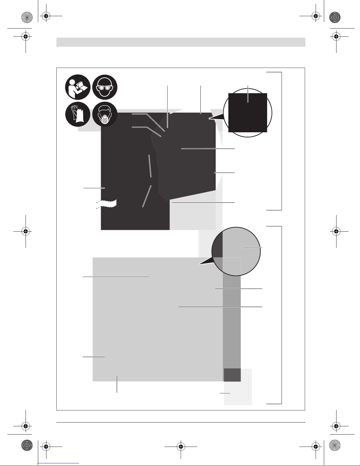
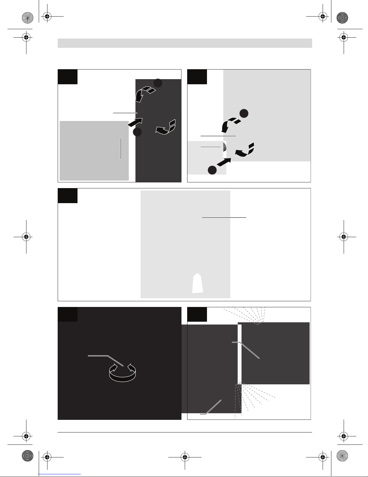
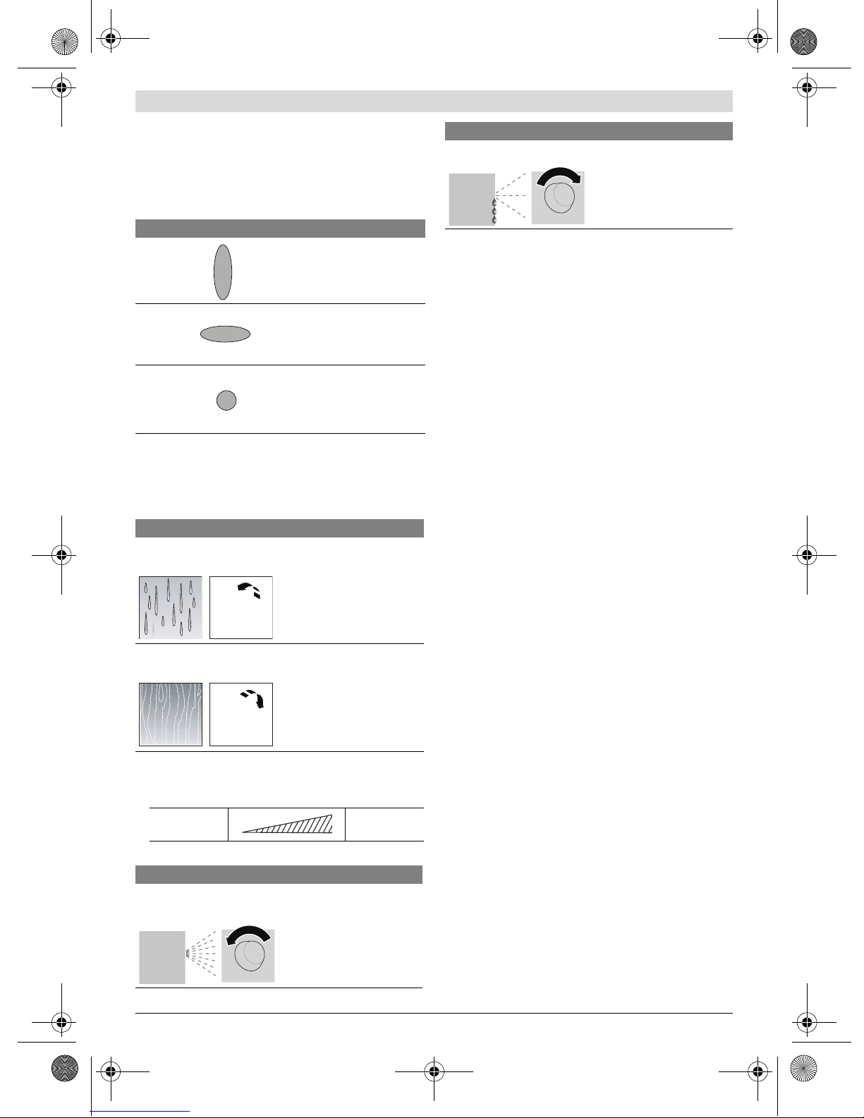
Filling in Spray Material (see figures C1–C2)
fBefore any work on the machine itself, pull the mains
plug.
– Unscrew the container 8from the spray gun.
– Turn the suction tube 10 so that the spray material can be
sprayed with almost no residue:
– Fillthespraymaterialinto the container and screw the con-
tainer firmly to the spray gun.
Starting Operation
fObserve correct mains voltage! The voltage of the pow-
er source must agree with the voltage specified on the
nameplate of the machine. Power tools marked with
230 V can also be operated with 220 V.
fDuring operation, the base unit must always stand hor-
izontally on a level surface. Never tilt the base unit or
set it upright when switched on.
fPay attention that the base unit cannot draw in dust or
other contamination during operation.
fMake sure never to spray on the base unit.
Switching On
– Always place the base unit horizontally on a level and clean
surface.
– Plug the mains plug into a socket outlet.
– Grasp the spray gun by the handle and point it at the spray
surface.
– For switching on, turn the control knob 16 on thebase unit
toward the right to the stop.
It is recommended to start with the maximum air
flow. (“Adjusting the Air Flow”, see page 18)
– Pull the trigger switch 9on the spray gun.
Note: When the base unit is switched on, air always flows out
at the nozzle 11.
Switching Off
– Release the trigger switch 9and turn the control knob 16
toward the left to the stop.
– Place down the spray gun in the set-down port 17.
– Pull the mains plug from the socket outlet.
Working Advice
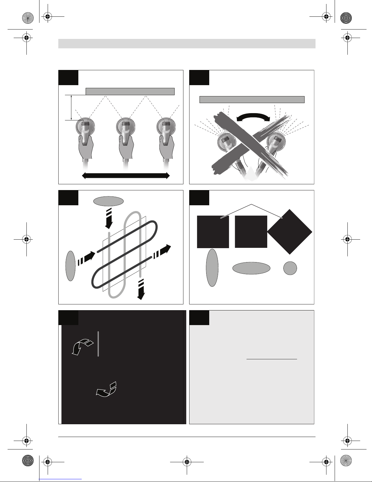
Spraying (see figures D–E)
Note: Observe the wind direction whenoperating the power
tool outdoors.
– Firstly, carry out a test-spray run and adjust the spray pat-
tern and the spray material quantityaccording to thespray
material. (For adjustments, see the following sections)
– Makesureto hold thespraygun vertical tothespray object
at a uniform clearance between 5 – 15 cm.
– Begin the spraying procedure outside the target area.
– Move the spray gun evenly cross-wise or up-and-down, de-
pending on the spray pattern setting.
Anevensurface qualityisachieved when the pathsoverlap
by4–5cm.
– Avoid interruptions within the spray surface.
Guiding the spray gun evenly will provide uniform surface
quality.
Non-uniform clearance and spray angle lead to heavy forma-
tion of paint mist and thus to an uneven surface.
– End the spraying procedure outside the target area.
Never spray the container completely empty. When the suc-
tion tube no longer immerses in the spray material, the spray
jet will break off, resulting in a non-uniform surface.
When coating material builds up on the nozzle and air cap,
clean both parts with the corresponding solvent.
Spray material Recommended
dilution
Wood preservatives, mordants/strip-
pers, oils, varnishes, impregnations,
rust-protection primers
undiluted
Disinfectants, plant protectants, water,
wallpaper stripper
undiluted
Solvent or water-dilutable paints,
primers, radiator paint, automotive top
coats, thick-coat finishes
At least 10 %
diluted
Amount of spray material [ml] 200 300 400 500
Paint thinner [ml] 20 30 40 50
For spray jobs on horizontal
surfaces/objects
toward the front in nozzle
direction
For spray jobs overhead toward the rear in handle
direction
OBJ_BUCH-420-002.book Page 17 Tuesday, August 23, 2011 12:08 PM

18 | English
1 609 929 Y14 | (23.8.11) Bosch Power Tools
Adjusting the Spray Pattern (see figure F)
fNever actuate the trigger switch 9 while adjusting the
air cap 2.
– Loosen the union nut 3.
– Turn the air cap 2to the requested position.
– Firmly retighten the union nut.
Adjusting the Spraying Capacity (see figure G)
– To adjust the requested spraying capacity, turn the thumb-
wheel 5:
I: Min. spraying capacity,
IIII: Max. spraying capacity.
Adjusting the Air Flow (see figure H)
– Turn control knob 16 to adjust the air flow and the pres-
sure for the spray material being used.
It is recommended to start with the maximum air flow.
Transport
The filled spray gun or a closed container with spray material
can be placed in the set-down port 17 for transport. The hold-
ing fixture retains the spray gun firmly in the set-down port.
Spray material cannot run out.
– Placedownthe spraygunon theset-downportandpushin
against the resistance until tightly seated.
Maintenance and Service
Maintenance and Cleaning
fBefore any work on the machine itself, pull the mains
plug.
Cleaning (see figures I–K)
Proper cleaning is the requirement for flawless operation of
the spray gun. Improper or lack of cleaning voids warranty
claims.
Always clean the spray gun and the container with the respec-
tive diluting agent (paint thinner or water) for the spray mate-
rial being used.
Never immerse the complete spray gun into the cleaning
agent.
Never clean the nozzle and air holes of the spray gun with
pointed metal objects.
Donotpour diluted spraymaterial back intotheoriginalspray
material drum/tin for storage.
Clean the spray gun thoroughly after having sprayed material
hazardous to one's health.
– Switch the base unit off and pull the trigger switch 9of the
spray gun so that the spray material can flow back into the
container.
– Unscrew the container 8and empty the remaining spray
material.
– Fill diluting agent (paint thinner or water) into the contain-
er and screw it to the spray gun.
– Shake the spray gun several times.
– Switchthebase unit on andspraythe dilutingagentinto an
empty material tin.
– Repeat the last three steps until cleardilutingagentemerg-
es from the spray gun.
– Switch the base unit off again.
– Completely empty the container 8.
– Check if the suction tube with the container seal 10 is free
of spray material and undamaged.
– Clean the outside of the container and the spray gun with a
cloth moistened in paint thinner.
– Unscrew the union nut 3and the air cap 2.
Air cap Jet Application
A
Vertical flat jet for horizontal
working direction
B
Horizontal flat jet for vertical
working direction
C
Round jet for corners, edges and
hard to reach locations
Spraying capacity Adjustment
Too much material on target
area:
The spraying capacity must
be reduced.
– Turn the thumbwheel 5in
direction I.
Not enough material on target
area:
The spraying capacity must
be increased.
– Turn the thumbwheel 5in
direction IIII.
Minimal
air flow
Maximum
air flow
Air Flow Adjustment
Too much fog of coating
material:
The air flow must be
reduced.
– Turn control knob 16
toward the left.
Atomisation too coarse: The air flow must be
increased.
– Turn control knob 16
toward the right.
Air Flow Adjustment
OBJ_BUCH-420-002.book Page 18 Tuesday, August 23, 2011 12:08 PM

English | 19
Bosch Power Tools 1 609 929 Y14 | (23.8.11)
– Clean the nozzle 11 and the nozzle needle with diluting
agent.
From time to time, the nozzle seal 12 must also be cleaned.
– Remove the nozzle 11 and the nozzle seal 12.
If required, use a pointed object, as the nozzle seal is seat-
ed firmly to the spray gun.
– Clean the nozzle seal with diluting agent.
– Reinstallthenozzlesealinthespray gun.Pay attentionthat
the groove points away from the spray gun.
– Mount the nozzle onto the spray gun body and turn it to the
correct position.
– Mounttheaircap2onto the nozzle and tighten with the un-
ion nut 3.
Changing the Air Filter (see figure L)
The air filter must be replaced when soiled.
– Remove the air filter cover 21.
– Change the air filter.
– Remount the air filter cover.
Material Disposal
Diluting agent and remainders of spray material must be dis-
posed of in an environmentally-friendly manner. Observe the
manufacturer’sdisposalinformationand the local regulations
for disposal of hazardous waste.
Chemicals harmful to the environment may not be disposed
of into soil, groundwater or bodies of water. Never pour
chemicals harmful to the environment into the sewerage sys-
tem!
Correction of Malfunctions
Problem Cause Corrective Measure
Spray material does not cover
properly
Spraying capacity too low Turn thumbwheel 5in direction IIII
Clearance to target area too large Reduce spray distance
Not enough spray material on target area,
too few spray paths sprayed over target area
Apply more spray paths over target area
Spray material too viscous Thin down the spray material by 10% again
and carry out a test-spray run
Spray material runs off after
coating
Too much spray material applied Turn thumbwheel 5in direction I
Clearance to target area too close Increase spray distance
Viscosity of spray material too low Add original spray material
Spray material applied too often over same
spot
Remove spray material; reduce number of
spray paths over same spot
Atomisation too course Spraying capacity too high Turn thumbwheel 5in direction I
Air flow too low Turn control knob 16 toward the right
Nozzle 11 soiled Clean nozzle
Too little pressure build-up in container 8Screw container firmly against spray gun
Spray material too viscous Thin down the spray material by 10% again
and carry out a test-spray run
Air filter heavily soiled Changing the Air Filter
Excessive paint mist Too much spray material applied Turn thumbwheel 5in direction I
Clearance to spray surface too large Reduce spray distance
Viscosity of spray material too low Reduceair flow;turn control knob 16toward
the left
Spray jet pulsates Not enough spray material in container Refill spray material
Venting hole on suction tube 10 clogged Clean suction tube and hole
Air filter heavily soiled Changing the Air Filter
Spray material too viscous Thin down the spray material by 10% again
and carry out a test-spray run
Spray material drips from the
nozzle
Build-up of spray material on nozzle 11 and
air cap 2Clean nozzle and air cap
Nozzle 11 worn Replace nozzle
Nozzle 11 loose Tighten union nut 3
OBJ_BUCH-420-002.book Page 19 Tuesday, August 23, 2011 12:08 PM

20 | English
1 609 929 Y14 | (23.8.11) Bosch Power Tools
Maintenance
If the machine should fail despite the care taken in manufac-
turingand testing procedures,repair shouldbecarried out by
an after-sales service centre for Bosch power tools.
In all correspondence and spare parts order,pleasealways in-
clude the 10-digit article number given on the type plate of
the machine.
After-sales Service and Customer Assistance
Our after-sales service responds to your questions concern-
ing maintenance and repair of your product as well as spare
parts. Exploded views and information on spare parts can al-
so be found under:
www.bosch-pt.com
Our customer service representatives can answer your ques-
tions concerning possible applications and adjustment of
products and accessories.
Great Britain
Robert Bosch Ltd. (B.S.C.)
P.O. Box 98
Broadwater Park
North Orbital Road
Denham
Uxbridge
UB 9 5HJ
Tel. Service: +44 (0844) 736 0109
Fax: +44 (0844) 736 0146
E-Mail: boschservicecentre@bosch.com
Ireland
Origo Ltd.
Unit 23 Magna Drive
Magna Business Park
City West
Dublin 24
Tel. Service: +353 (01) 4 66 67 00
Fax: +353 (01) 4 66 68 88
Australia, New Zealand and Pacific Islands
Robert Bosch Australia Pty. Ltd.
Power Tools
Locked Bag 66
Clayton South VIC 3169
Customer Contact Center
Inside Australia:
Phone: +61 (01300) 307 044
Fax: +61 (01300) 307 045
Inside New Zealand:
Phone: +64 (0800) 543 353
Fax: +64 (0800) 428 570
Outside AU and NZ:
Phone: +61 (03) 9541 5555
www.bosch.com.au
Republic of South Africa
Customer service
Hotline: +27 (011) 6 51 96 00
Gauteng – BSC Service Centre
35 Roper Street, New Centre
Johannesburg
Tel.: +27 (011) 4 93 93 75
Fax: +27 (011) 4 93 01 26
E-Mail: [email protected]
KZN – BSC Service Centre
Unit E, Almar Centre
143 Crompton Street
Pinetown
Tel.: +27 (031) 7 01 21 20
Fax: +27 (031) 7 01 24 46
E-Mail: bsc.dur@za.bosch.com
Western Cape – BSC Service Centre
Democracy Way, Prosperity Park
Milnerton
Tel.: +27 (021) 5 51 25 77
Fax: +27 (021) 5 51 32 23
E-Mail: [email protected]
Bosch Headquarters
Midrand, Gauteng
Tel.: +27 (011) 6 51 96 00
Fax: +27 (011) 6 51 98 80
E-Mail: rbsa-hq.[email protected]
No spray material emerges from
the nozzle
Control knob 16 for air-flow control turned
too far to the left
Turn control knob 16 toward the right
No pressure build-up in container 8Screw container firmly against spray gun
Suction tube 10 loose Insert suction tube properly
Nozzle 11 clogged Clean nozzle
Suction tube 10 clogged Clean suction tube
Venting hole on suction tube 10 clogged Clean suction tube and hole
Spray material too viscous Thin down the spray material by 10% again
and carry out a test-spray run
Problem Cause Corrective Measure
OBJ_BUCH-420-002.book Page 20 Tuesday, August 23, 2011 12:08 PM
This manual suits for next models
1
Table of contents
Other Bosch Paint Sprayer manuals

Bosch
Bosch PPR 250 User manual

Bosch
Bosch PFS 1000 User manual

Bosch
Bosch PFS 5000 E User manual

Bosch
Bosch PFS 3000-2 User manual

Bosch
Bosch PFS 55 User manual

Bosch
Bosch PFS 1000 User manual

Bosch
Bosch PFS 55 User manual

Bosch
Bosch PFS 55 User manual

Bosch
Bosch PFS 55 User manual

Bosch
Bosch PFS 105 E User manual

Bosch
Bosch PFS 7000 User manual

Bosch
Bosch 0603206200 User manual

Bosch
Bosch PFS 5000E User manual

Bosch
Bosch PFS 3000-2 User manual

Bosch
Bosch PFS 1000 User manual

Bosch
Bosch 2 608 190 048 User manual

Bosch
Bosch PFS 55 User manual

Bosch
Bosch PFS 3000-2 User manual

Bosch
Bosch PFS 65 User manual

Bosch
Bosch PFS 5000 E User manual