Norac UC5 Topcon X30 User manual

Quick Guide
Ag Leader®Display

Printed in Canada
Copyright 2010 by NORAC Systems International Inc.
Reorder P/N: UC5-BC-MANUAL-AL-QUICK GUIDE Rev B
NOTICE: NORAC Systems International Inc. reserves the right to improve products and their specifications without notice and
without the requirement to update products sold previously. Every effort has been made to ensure the accuracy of the information
contained in this manual. The technical information in this manual was reviewed at the time of approval for publication.

Contents
1SAFETY PRECAUTIONS......................................................................................... 1
1.1Warranty Registration............................................................................................................................................................1
2TECHNICAL SPECIFICATIONS ............................................................................ 2
3SYSTEM DESCRIPTION .......................................................................................... 3
3.1General UC5 System Layout.................................................................................................................................................3
3.2Height Sensors .........................................................................................................................................................................4
3.3Roll Sensors ..............................................................................................................................................................................4
3.4Modules .....................................................................................................................................................................................4
4OPERATION.............................................................................................................. 5
4.1Main Run Screen......................................................................................................................................................................5
4.2Setting Control Options ........................................................................................................................................................6
4.3Sprayer Manual Boom Height Switches..............................................................................................................................7
5SETUP......................................................................................................................... 8
5.1Automatic System Setup........................................................................................................................................................8
5.2Retune........................................................................................................................................................................................9
6MAINTENANCE...................................................................................................... 10
7MENU STRUCTURE............................................................................................... 11

1
1Safety Precautions
The UC5 Spray Height Control system will greatly improve your spraying height accuracy and
protect the boom against damage in a wide variety of field conditions. However, under some
circumstances performance may be limited. The operator of the sprayer must remain alert at
all times and override the automatic control when necessary.
Important
Under no circumstances should any service work be performed on the machinery
while the UC5 Spray Height Control system is in the Automatic Mode.
Always ensure that the UC5 Spray Height Control system is powered down or in
Manual Mode:
Before leaving the operator’s seat.
While the machine is not moving.
When transporting the machine.
Before working on any part of the booms:
Set the UC5 system to Manual Mode.
Turn the sprayer engine off.
Do not operate this system before:
Reading and understanding the operator’s manual.
Thoroughly understanding the machine operation.

2
2Technical Specifications
CAN ICES-3(A)/NMB-3(A)
This device complies with part 15 of the FCC Rules. Operation is subject to the following two
conditions: (1) This device may not cause harmful interference, and (2) this device must accept
any interference received, including interference that may cause undesired operation.
This equipment has been tested and found to comply with the limits for a Class A digital device,
pursuant to part 15 of the FCC Rules. These limits are designed to provide reasonable
protection against harmful interference when the equipment is operated in a commercial
environment. This equipment generates, uses, and can radiate radio frequency energy and, if not
installed and used in accordance with the instruction manual, may cause harmful interference to
radio communications. Operation of this equipment in a residential area is likely to cause
harmful interference in which case the user will be required to correct the interference at their
own expense.
This Class A digital apparatus complies with Canadian ICES-003.
Pursuant to EMC Directive – Article 9, this product is not intended for residential use.
Table 1: System Specifications
Supply Voltage (rated)
12VDC
Supply Current (rated)
10
A
Hydraulic Pressure (maximum)
3300 psi
Baud Rate 250 kbps
Clock Frequency (maximum)
96 MHz
Solenoid Valve PWM Frequency
300 Hz
Ultrasonic Sensor Transmit Frequency
50 kHz
Operating Temperature Range
0°C to 80°C

3
3System Description
3.1 General UC5 System Layout
Figure 1: General UC5 System Layout
Item Description
Item
Description
1 14 Awg Cable
10
Roll Sensors
2 18 Awg Cable
11
V
alve Module
3 Bus Terminato
r
12
V
alve Block
4 2 Way Couple
r
13
Input Module
5 3 Way Couple
r
14
Left Outer Height Sensor
6 8 Way Couple
r
15
Left Inner Height Sensor (optional)
7 Display
16
Main Lift Height Senso
r
8 Control Module
17
Right Inner Height Sensor (optional)
9 + 12 VDC Source
18
Right Outer Height Sensor
* Some UC5 Spray Height Control kits may not include all the components listed above.

4
3.2 Height Sensors
Height sensors use an ultrasonic signal to measure distance to the ground or crop canopy.
Normally there are three height sensors used. A sensor is mounted to the outer part of
each boom tip, and another sensor is mounted to the center section.
3.3 Roll Sensors
Roll sensors are important for measuring boom and sprayer roll dynamics.
Two roll sensors are normally used for a UC5 Spray Height Control system.
The mounting position of the roll sensors vary from sprayer to sprayer depending on
boom geometry and suspension.
3.4 Modules
Normally there are three modules included: a control module, an input module, and a
valve module.
Module status is indicated by a LED. Shortly after power-up, the module should present a
solid green light, indicating the module is functioning and ready.
5
4Operation
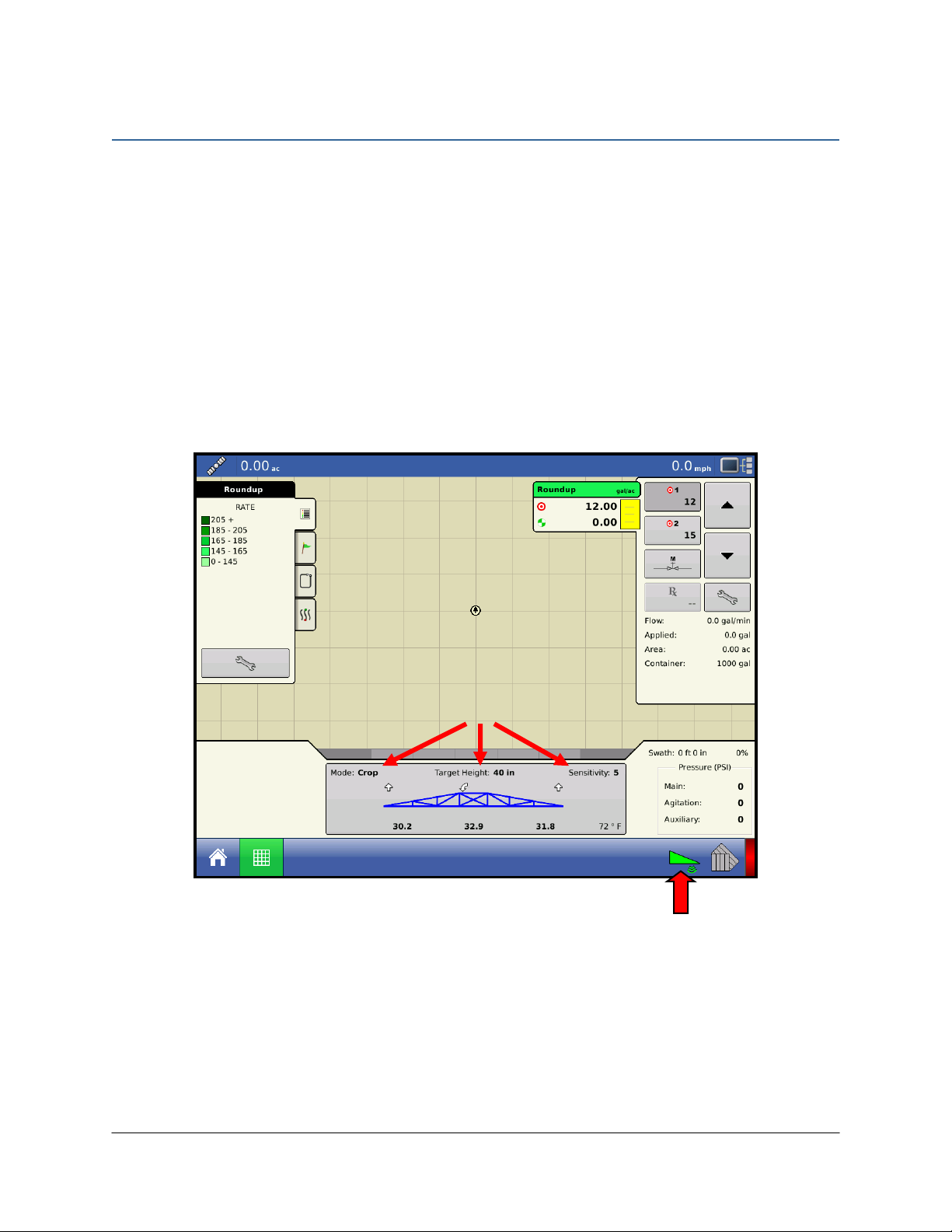
4.1 Main Run Screen
The majority of functional settings and controls can be accessed on the main run screen. An
image of the boom, with the height of each boom section is displayed.
To change between Automatic and Manual Mode, press the corresponding button. When the
boom is blue, the UC5 system is in Automatic Mode. When the boom is black, the UC5
system is in Manual Mode. If the boom is above normal working height, a warning message will
appear requiring permission to allow Automatic Mode.
When the UC5 Height Control system is in Automatic Mode, arrows will appear on the screen
above or below the boom sections. These arrows indicate the UC5 system is making a
correction to part of the boom in the displayed direction. Often times the correction will be
very small and there may not be a noticeable change in boom position.
Figure 2: Main Run-Screen
The height displayed on the boom is measured from the spray nozzles to the soil (Soil Mode)
or to the crop canopy (Crop Mode). If there are five height sensors on the sprayer, the height
displayed is the average for each boom section.
Auto / Manual
Button
Settings

6
4.2 Setting Control Options
To change these settings, click the Settings button to display the boom height control options
screen as shown in Figure 3.
Figure 3: Boom Height Control Settings Screen
Sensitivity:
The Sensitivity can be adjusted from 1 to 10, with 5 being the default setting. A lower number
will reduce the system sensitivity and improve stability. Higher settings will speed up the
response and also create a greater demand on the hydraulics.
Mode:
The Mode button allows the system to be changed between Soil Mode, Crop Mode and Hybrid
Mode. Soil Mode allows the sensors to read a height from the spray nozzles to the ground;
whereas Crop Mode will read the height from the spray nozzles to the top of the crop canopy.
Hybrid Mode is an improved Crop Mode and is recommended in place of Crop Mode.
Target Height:
The Target Height is the height you would like the boom to be set at when spraying. When
operating in Soil Mode, the Target Height is measured from the spray nozzles to the soil. In
Crop Mode the Target Height is measured from the crop canopy to the spray nozzles.

7
4.3 Sprayer Manual Boom Height Switches
When a manual switch is pressed, an arrow will be displayed on the screen showing which
function is being activated. For example, if the left up switch is pressed then an up arrow will
be shown above the left boom.
Tilt (Variable Geometry) Switches:
While in Automatic Mode if either left or right tilt switches are pressed, the corresponding
boom section will go into Manual Mode. To return all boom sections to Automatic Mode,
press the Auto button. If the Double Tap Wings function is enabled, the tilt down switches can
be used to resume Automatic Mode.
Main Lift Switch:
While in Automatic Mode if the main lift up or down switch is momentarily pressed, the Target
Height is incrementally adjusted up or down.
Pressing and holding the main lift switch will always put the system into Manual Mode. If the
Double Tap Main function is enabled, the main lift down switch can be used to resume
Automatic Mode.
* Some sprayer types may not have all the functionality listed above.

8
5Setup
There are two methods to setup the UC5 system. The recommended way is to use the
Automatic Setup as shown in Section 5.1. The alternative method is to use Manual Setup,
which is intended for expert users and troubleshooting.
5.1 Automatic System Setup
Unfold the sprayer in a location that is relatively level and where the sensors are over bare soil
or gravel. Do not conduct the Automatic Setup or Retune procedures over standing crop or
weeds/grass. Also, avoid concrete or asphalt surfaces.
Ensure the boom roll suspension system is functioning properly and smoothly. Friction on
wear surfaces can be relieved using lubricants (grease, etc) or adjustment. Properly tuned
suspension systems will optimize UC5 performance.
For best results, the hydraulic system should be under a normal load and at a normal working
temperature.
Start the solution pump and run the sprayer’s engine at a normal working RPM for the
entire setup.
Cycle all boom sections up and down manually for five minutes to warm the oil.
For pull-type sprayers, ensure any hydraulic flow controls are adjusted for normal field
operation.
Changing the hydraulic flow controls after or during the Automatic Setup will affect the
UC5 performance.
Important
All boom sections will move during the Automatic Setup.
People and equipment must be clear of sprayer boom.
Ensure the booms have sufficient range to lift fully and are clear of any power
lines.

9
To start the setup press the “Automatic Setup” button from the Setup screen. The system will
go through the following steps as it progresses through the Automatic Setup. Some steps may
not be used depending on the sprayer type.
Select the sprayer type:
From the selection boxes, choose your sprayer make and model and then press the
Check button.
A list of precautions will be displayed. Press “Check” to continue.
A list of connected modules will be displayed. Press “Check” to continue.
Wiring Test:
The system will instruct you to move boom functions using the sprayer controls. Move
each boom as instructed on the display.
Sensor Detect:
You will then be instructed to manually adjust the boom height so the nozzles are 90 cm
(35 inches) from the ground on all sections. When the measured distance is 90 cm press
“Check”.
The system will now instruct you to press and hold “Check” while it detects the sensors
on the booms.
Boom Geometry Tuning:
Exit the cab and manually push either boom tip down 30 to 90 cm for a moment and then
let go. Do not walk near the sensors when approaching the boom. Stay at least 1 meter
from the sensor to not induce a measurement error.
Hydraulic Tuning:
Press and hold the “Check” button to continue with the hydraulic tuning. If “Check” is
released before the tuning is finished, simply press and hold again to continue the
procedure.
The system will display various messages as it is working. The messages are displayed for
informational purposes only. When the system is finished the hydraulic tuning the
Automatic Setup is complete.
5.2 Retune
On occasion it is necessary to recalibrate the hydraulics of the NORAC UC5 Height Control
system. When you press the “Retune” button from the Setup screen, the system will go
through only the “Hydraulic Tuning” portion of the Automatic Setup. You may want to
perform a Retune when:
A hydraulic solenoid has been changed.
A hydraulic pump has been changed or adjusted.
A different tractor has been connected to the sprayer.
The tractor’s hydraulic flow control has been adjusted.

10
6Maintenance
The NORAC Spray Height Control system requires very little maintenance, but there are a few
procedures that will ensure the system continues to work correctly for many years.
Before each day:
It is highly recommended that the sprayer friction pads are greased. To ensure optimum
performance this should be done daily. This will ensure the boom is pivoting
separately from the sprayer. It is very important to keep the friction pads greased on
Active Roll™ systems.
Ensure the height sensor breakaway brackets are functioning correctly. Apply grease to the
moving parts if necessary, to ensure they return to center after a break-away occurs.
Ensure there is a clean, dry foam disc inserted in each sensor. If it is clogged with dust or
other debris, clean it as described below.
At the end of the season:
Replace the oil filter in the NORAC hydraulic manifold annually (NORAC P/N 106285).
Cleaning Ultrasonic Height Sensors:
Remove the foam disc from the sensor and wash it with clean water. Squeeze out excess
water and allow the foam disc to dry. The sensor can be used if the foam is wet, however
you may not get a valid height reading until it is completely dry.
If the transducer inside the sensor is also dirty, wash it using clean water. Remove the
sensor from the bracket and rinse debris from the transducer by pouring water
across the face of the sensor. Do not submerge or pressure-wash the sensor. A
soft bristle brush can also be used to gently clean the transducer if water alone is not
sufficient. Use caution not to scratch or tear the transducer as it is fragile. The sensor
should be left to dry with the transducer facing downwards. The sensor can be used if it is
wet, however you may not get a valid height reading until it is completely dry. Leaving the
control system powered on with the sensor connected and facing down will speed the
process of drying the sensor.
Chemicals or compressed air should never be used to clean the sensor.
11
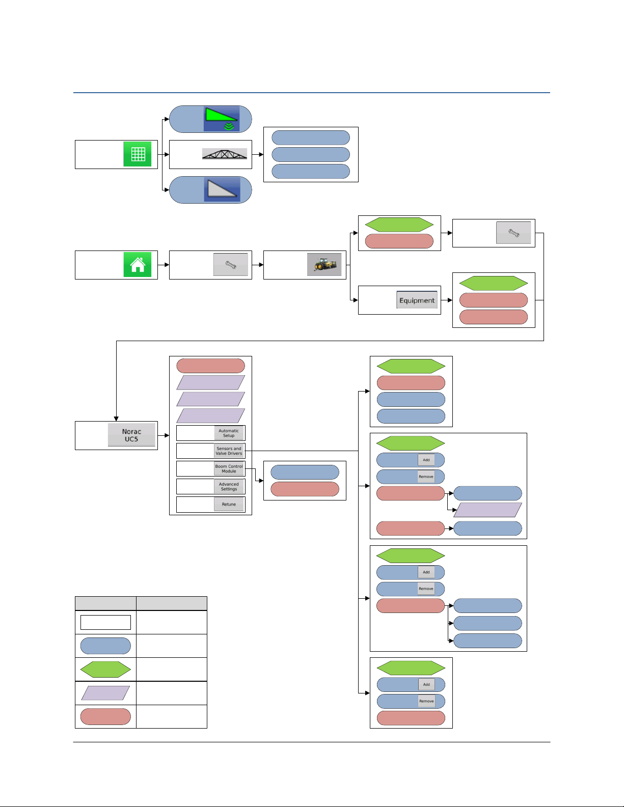
7Menu Structure
NORAC
UC5
Motion Detection
Source
Selected Component
Firmware Version
Selected Component
Hardware Version
Sprayer
Configuration
Automatic
Setup
Sensors &
Valve Drivers
Boom Control
Module
Advanced
Settings
Retune
System Components
Minimum Height Mode
Soil Mode
General
Crop Mode
Height Sensors
Sensor
Roll Sensors Measured Roll
Temperature
Nozzle Height
Add
Remove
Valves
Valve
Deadzone
Test Valve
Gain
Add
Remove
Swtich
Configured Switches
Add
Remove
Rectangle
Symbol
Setting
Indicates that a new
page is displayed.
Indicates a selection or
setting that is changed
in the current page.
Meaning
Indicates the tab where
the selection or setting
is located.
Tab
Indicates non-selectable
or non-changeable
setting information.
Info
List
Indicates a selection or
setting that is changed
from a list.
Run Screen
Sensitivity
Crop / Soil / Hybrid Mode
Target Height
Manual
Auto
Settings
Home Screen Settings Configuration
Settings
Settings
Equipment
Select Sprayer
Configuration
Select Vehicle
Boom Control
Vehicle

TOPCON Agriculture Canada
3702 Kinnear Place
Saskatoon, SK S7P 0A6
TOPCON Agriculture Americas
W5527 Hwy 106
Fort Atkinson, WI 53538
TOPCON Precision Agriculture Europe
Avenida de la industria,
35, Tres Cantos, España
Spain
Support
Phone: 888 979 9509
Web: www.norac.ca
Other manuals for UC5 Topcon X30
55
Table of contents
Other Norac Paint Sprayer manuals

Norac
Norac UC4.5 User manual

Norac
Norac UC5 Topcon X30 User manual

Norac
Norac UC4+ User manual

Norac
Norac UC4.5 User manual

Norac
Norac UC5 Topcon X30 User manual

Norac
Norac UC4.5 User manual

Norac
Norac UC4+ User manual

Norac
Norac Rogator 1286C User manual

Norac
Norac UC4+ User manual

Norac
Norac UC5 Topcon X30 User manual


