EN | 5
D222TD | Installation Instructions |
Bosch Security Systems | 12/03 | 74-07391-000-B
3.0 Installation
9. Connect the keypad wire to the control panel.
The maximum length for all wires connected to
D2212 Terminal 8 combined is 152 m (500 ft).
Route the data wire away from electrical, telephone,
and other data wiring.
Figure 4 shows a typical installation using one
D222TD Keypad. Use parallel connections for
additional keypads or expanders.
For more information, refer to the D2212 Installation
Guide (P/N: 74-07361-000).
10. Assign the D222TD to a device address.
Before you begin, make sure the control
panel’s standby pin is locked down to
prevent sending missing point reports.
To set the D222TD address:
a. Set DIP Switch 1 to the ON position.
b. The display shows:
SET ADDRESS MODE
ADDRESS IS ##
c. Enter the address (1 to 8) with a leading zero.
For example, 01 for Address 1.
Only use address numbers 1 to 8.
d. Return DIP Switch 1 to the OFF position.
When using more than one D222TD Keypad,
set one of the keypads to Address 1.
The control panel’s program affects the keypad’s
address. Choose the keypad address in the control
panel’s program. Then select either the Text
Keypad or Text Keypad with Points option for the
device type’s address.
See Address Configuration in the D2212 Program Entry
Guide (P/N: 74-07386-000) for more information.
When replacing a D222TD at Address 1, if the
system has custom text, preserve the custom text by:
a. Copying the control panel’s program using a
D5200.
b. Attaching a new D222TD at Address 1.
c. Reprogramming the control panel using the
copied program.
11. Disable the sounder.
Set DIP Switch 3 to the OFF position.
(see Figure 4).
The fire points need the trouble sounder. Disabling
the sounder with DIP Switch 3 stops the D222TD
from annunciating fire point trouble.
If this system has fire points installed,
contact the local authority having jurisdiction
(AHJ) to verify the code requirements for fire
trouble sounders before disabling the
D222TD sounder.
Enable the sounder for Underwriters
Laboratories, Inc. (UL) systems. For UL
installations, the sounder on at least one
keypad in the system must remain
connected.
12. Adjust the D222TD display.
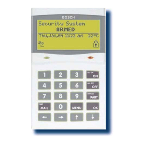
After mounting the D222TD, view the display from
the user’s perspective. If the display requires
adjustment for clarity, use the display adjustment
potentiometer (R50) in the lower right-hand corner
of the D222TD circuit board.
13. Replace the front cover.
a. Align the top two tabs of the enclosure cover
with the top two tab slots in the enclosure
base.
b. Slide the top of the cover into the base.
c. Gently push the bottom of the cover down on
the base until it snaps into place.
14. Adjust the keys.
Push each key on the keypad towards the top of the
enclosure making sure it fits with the opening in the
top cover.
Figure 4: Wiring the D222TD to the D2212
1 - D222TD Keypad 4 - Red wire
2 - D2212 Control Panel 5 - Green wire
3 - Black wire
1
23
456
789
0
A
B
C
*
1
CLEAR
11 12
6
7
8
9
10
On
AL L O N
SYSTEM OK
3
45
2
