manuals.online logo
Brands
  1. Home
  2. •
  3. Brands
  4. •
  5. CALEFFI
  6. •
  7. Water Filtration System
  8. •
  9. CALEFFI HydroLink 559921A User manual

CALEFFI HydroLink 559921A User manual

HydroLink
™
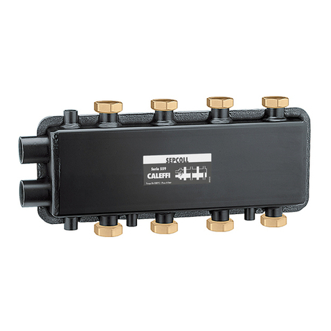
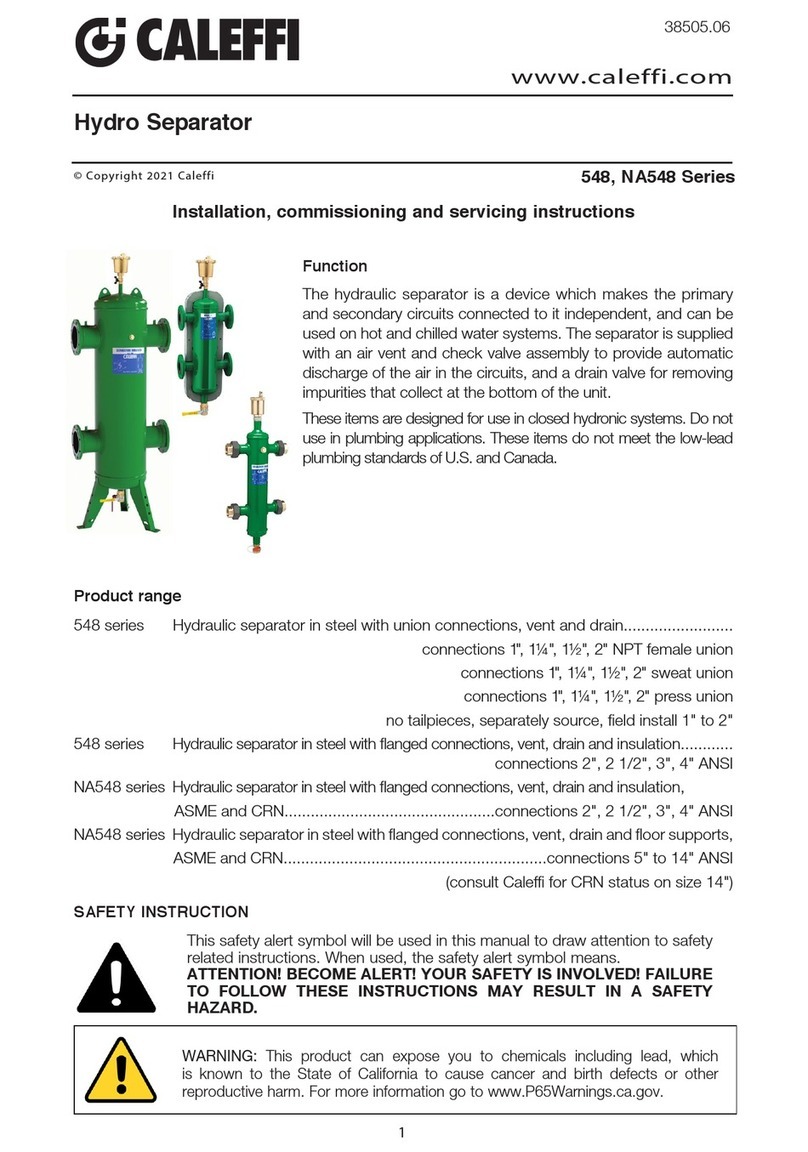
Function
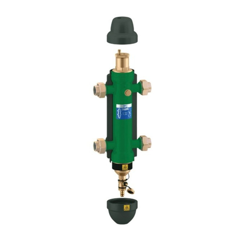
The Hydrolink
™
, combining a hydraulic separator with a
distribution manifold, is used in heating and air-conditioning
systems. It provides a chamber to hydraulically separate the
boiler (or chiller) circuit from the distribution circuits and also
provides a self-contained manifold station that supplies up
to four independently controlled load circuits with the same
supply temperature. Available configurations are compact,
and can be easily installed in any hydronic system, saving
space.
Product range
Code 559920A 2+0 separator-manifold with built-in mounting brackets and pre-formed
insulation. Size: 1" NPT female main; 1" NPT male branches.
Code 559921A 2+1 separator-manifold with built-in mounting brackets and pre-formed
insulation. Size: 1" NPT female main; 1" NPT male branches.
Code 559922A 2+2 separator-manifold with angle mounting brackets and pre-formed insulation.
Size: 1 1/4" NPT female main; 1" NPT male branches.
Code 559931A 3+1 separator-manifold with angle mounting brackets and pre-formed insulation.
Size: 1 1/4" NPT female main; 1" NPT male branches.
38483.03
Technical characteristics
Materials:
Body: painted steel
Maximum working pressure: 100 psi (7 bar)
Working temperature range: 32 to 230°F (0 to 110°C)
Performance:
Medium: Water and non-hazardous glycol solutions
Maximum glycol percentage: 50%
Connections: - main: 3+1 and 2+2: 1 1/4” NPT female
2+0 and 2+1: 1” NPT female
- branches: 3+1 and 2+2: 1” NPT male
2+0 and 2+1: 1” NPT male
- air vent valve: 1/2” NPT female
- drain valve: 1/2” NPT female
Center distances:
- main: 3+1 and 2+2: 3 1/8” (80 mm)
2+0 and 2+1: 2 3/8” (60 mm)
- branches: 3+1 and 2+2: 5” (125 mm)
2+0 and 2+1: 5” (125 mm)
Insulation
Material: EPP
Thickness: 3/4” (20 mm)
Density: 3 lb/ft3(45 kg/m3)
Thermal conductivity: 0.25 BTU/in (.037 W/mK) at 50°F (10°C)
Temperature range: 20 to 250°F (-5–120°C)
Reaction to fire (UL 94): class HBF
www.caleffi.com
© Copyright 2018 Caleffi
These items are designed for use in closed hydronic systems. Do not use in plumbing applications. These
items do not meet the low-lead plumbing standards of U.S. and Canada.
1
Flow Characteristics
Maximum recommended flow rates at connections:
CAUTION: If the HydroLink™device is not installed, commissioned and
maintained properly, according to the instructions contained in this
manual, it may not operate correctly and may endanger the user.
CAUTION: Make sure that all the connecting pipework is water tight.
CAUTION: When making the water connections, make sure that the
HydroLink™device connecting pipework is not mechanically over-
stressed. Over time this could cause breakages, with consequent water
losses which, in turn, could cause harm to property and/or people.
CAUTION: Water temperatures higher than 100°F (38°C) can be dangerous.
During the installation, commissioning and maintenance of the HydroLink™
device, take the necessary precautions to ensure that such temperatures do
not endanger people.
SAFETY INSTRUCTION
This safety alert symbol will be used in this manual to draw attention to safety related instructions.
When used, the safety alert symbol means ATTENTION! BECOME ALERT! YOUR SAFETY IS
INVOLVED! FAILURE TO FOLLOW THESE INSTRUCTIONS MAY RESULT IN A SAFETY
HAZARD.
CAUTION: All work must be performed by qualified personnel trained in the
proper application, installation, and maintenance of systems in accordance
with all applicable codes and ordinances.
Branches Primary
Secondary
(totals)
2+0 9 gpm (.56 l/s) 22 gpm (1.4 l/s)
2+1 9 gpm (.56 l/s) 22 gpm (1.4 l/s)
2+2 11 gpm (.70 l/s) 26 gpm (1.67 l/s)
3+1 11 gpm (.70 l/s) 26 gpm (1.67 l/s)
2
WARNING: This product can expose you to chemicals including lead, which is
known to the State of California to cause cancer and birth defects or other
reproductive harm. For more information go to www.P65Warnings.ca.gov.
Installation
HydroLink
™
units should be installed in
accordance with the diagrams shown in
this instruction manual, ensuring the correct
connection of the flow and return pipework
and the main and branch connections.
HydroLink
™
units can also be installed upside
down, as long as the connection logic shown is
followed.
The 1/2" NPT female connections must only be
used for connecting an air vent valve and drain
valve, and not for connecting branch circuits.
The air vent and drain valve are included in
shipment but not connected to the Hydrolink
™
.
Use a liquid anaerobic thread sealant to ensure
water tight connections.
Installation and Insulation Assembly
Procedures –
Models 2+2
and 3+1
HydroLink
™
models
2+2 and 3+1
are supplied
with angle wall-
mounting brackets, which allow the front-to-
back positioning to be adjusted.
After bracket mounting and leak-testing,
the pre-formed insulation shell should be
attached as described in points 1 and 2
below.
1. Remove the protection film from
the surface adhesive and assemble.
2. If the HydroLink™unit is to be used with
chilled water, spread a thin layer of sealant
around the outer edges of the pre-formed
insulation, wait until the solvent has
evaporated (about 10 minutes) and then
assemble.
0,25
0,5
0,75
1,0
1,25
1,5
1,75
2,0
2,25
100
80
60
40
20
-20-15-10-5051015
20
12
3
6
9
18
17
16
15
14
13
12
11
10
9
8
7
6
5
4
3
2
1
24
23
22
21
20
19
WATCH
CALEFFI
0,25
0,5
0,75
1,0
1,25
1,5
1,75
2,0
2,25
20
0,25
0,5
0,75
1,0
1,25
1,5
1,75
2,0
2,25
100
80
60
40
20
-20-15-10-5051015
20
12
3
6
9
18
17
16
15
14
13
12
11
10
9
8
7
6
5
4
3
2
1
24
23
22
21
20
19
WATCH
CALEFFI
0,25
0,5
0,75
1,0
1,25
1,5
1,75
2,0
2,25
20
3
Having chosen the box location, proceed as in points 1-2-3-4 below.
Installation and Insulation
Assembly Procedures -
Model 2 + 0 and 2 + 1
Examples of location
in manifold box
Service Instructions
There is no service required for the HydroLink™device.
Caleffi North America, Inc.
3883 West Milwaukee Road
Milwaukee, WI 53208
T: 414.238.2360 F: 414.238.2366
7-23-18
·
Installation Tip
Scan to view
5599 HydroLink™
4
Leave this manual for the user.
2. Mount the device to
the internal supports
in the manifold box.
3. Connect the piping, leak-
test and close the pre-formed
insulation shell after removing
the protection film from the
upper surface adhesive.
4. If the unit is to be used
with chilled water, see point
2 of the previous section.
1. Remove the protection film
from the lower surface adhesive
and position the HydroLink™
unit inside the insulation shell.

This manual suits for next models

3

Other CALEFFI Water Filtration System manuals
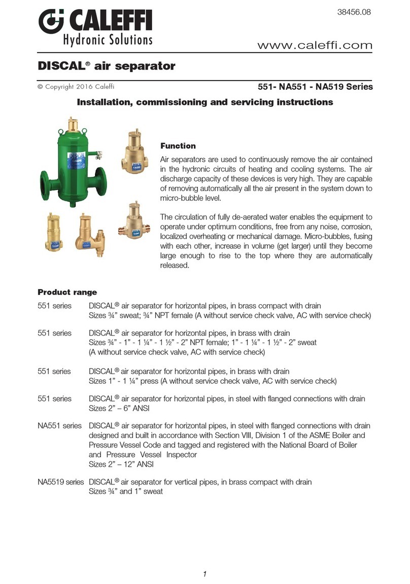
CALEFFI DISCAL 551 Series User guide

CALEFFI

CALEFFI DISCAL 551 Series User guide

CALEFFI 5370 Series User manual

CALEFFI

CALEFFI 5370 Series User manual

CALEFFI 5495 SEP4 User guide

CALEFFI

CALEFFI 5495 SEP4 User guide

CALEFFI 577 Series User manual

CALEFFI

CALEFFI 577 Series User manual

CALEFFI DIRTCAL 5462 Series User guide

CALEFFI

CALEFFI DIRTCAL 5462 Series User guide

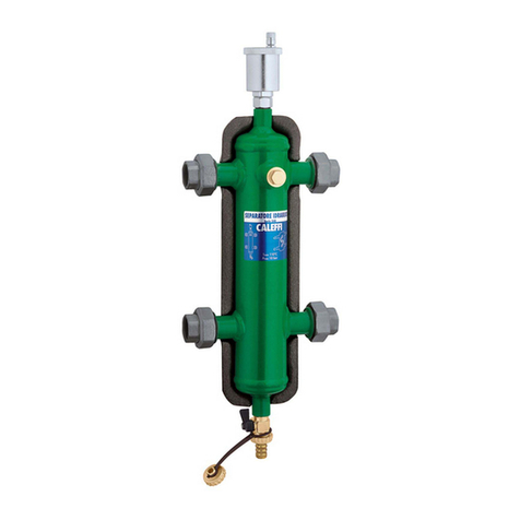
CALEFFI SEPCOLL 559 Series User manual

CALEFFI

CALEFFI SEPCOLL 559 Series User manual

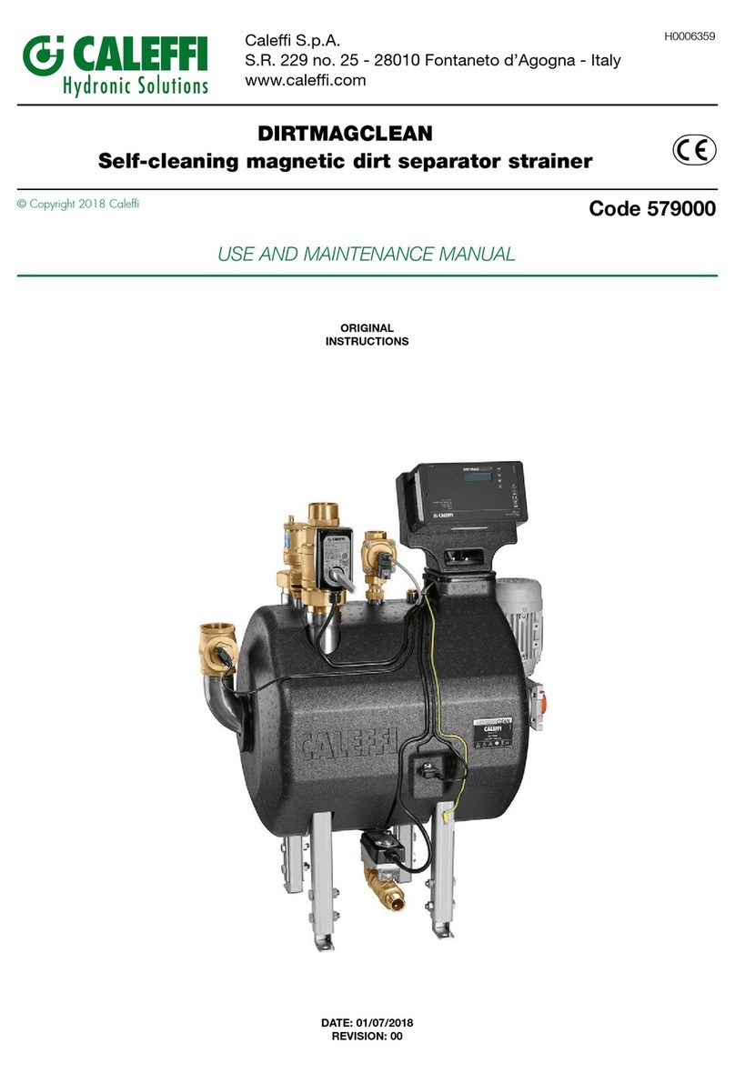
CALEFFI DIRTMAGCLEAN User manual

CALEFFI

CALEFFI DIRTMAGCLEAN User manual

CALEFFI DIRTCAL 5462 Series User manual

CALEFFI

CALEFFI DIRTCAL 5462 Series User manual

CALEFFI DISCAL NA551 Series User guide

CALEFFI

CALEFFI DISCAL NA551 Series User guide

CALEFFI DIRTMAG NA5453 Series User guide

CALEFFI

CALEFFI DIRTMAG NA5453 Series User guide

CALEFFI DIRTMAGCLEAN 579 Series Owner's manual

CALEFFI

CALEFFI DIRTMAGCLEAN 579 Series Owner's manual

CALEFFI 548 Series User manual

CALEFFI

CALEFFI 548 Series User manual

CALEFFI 5790 Series Guide

CALEFFI

CALEFFI 5790 Series Guide

CALEFFI DIRTMAG PRO 5463AM Series User guide

CALEFFI

CALEFFI DIRTMAG PRO 5463AM Series User guide

CALEFFI 580020 Owner's manual

CALEFFI

CALEFFI 580020 Owner's manual

CALEFFI 5709 Series User manual

CALEFFI

CALEFFI 5709 Series User manual

CALEFFI 5709 Series User manual

CALEFFI

CALEFFI 5709 Series User manual

CALEFFI DISCAL 5517 Series User guide

CALEFFI

CALEFFI DISCAL 5517 Series User guide

CALEFFI 5350 H Series User manual

CALEFFI

CALEFFI 5350 H Series User manual

CALEFFI 5495 Series User manual

CALEFFI

CALEFFI 5495 Series User manual

CALEFFI 546 Series User manual

CALEFFI

CALEFFI 546 Series User manual
CALEFFI 5495 SEP4 User guide

CALEFFI

CALEFFI 5495 SEP4 User guide

CALEFFI 548 Series User guide

CALEFFI

CALEFFI 548 Series User guide

Popular Water Filtration System manuals by other brands

Pentair FRESHPOINT GRO-575M Installation and operation manual

Pentair

Pentair FRESHPOINT GRO-575M Installation and operation manual

Lafaelt AcFee APF Operation manual

Lafaelt

Lafaelt AcFee APF Operation manual

Danfoss AAF 007 Safety guide

Danfoss

Danfoss AAF 007 Safety guide

Power Fist 8787681 user manual

Power Fist

Power Fist 8787681 user manual

Laica BFX.I39/k instruction manual

Laica

Laica BFX.I39/k instruction manual

EM-Technik 7F400 Assembly and operation instructions

EM-Technik

EM-Technik 7F400 Assembly and operation instructions

velda Floating Combi Filter 2500 User instructions

velda

velda Floating Combi Filter 2500 User instructions

Crystal Quest Thunder CQE-CT-00142 manual

Crystal Quest

Crystal Quest Thunder CQE-CT-00142 manual

Antunes UFL-420 Series owner's manual

Antunes

Antunes UFL-420 Series owner's manual

Fiap BioSieve Active 50.000 2840 manual

Fiap

Fiap BioSieve Active 50.000 2840 manual

Anchor DigiPure AF-9000 Series user guide

Anchor

Anchor DigiPure AF-9000 Series user guide

Pentair AUTOTROL MAGNUM 742 Installer manual

Pentair

Pentair AUTOTROL MAGNUM 742 Installer manual

Bunn Easy Clear EQ-17-TL specification

Bunn

Bunn Easy Clear EQ-17-TL specification

Triax 383900 quick guide

Triax

Triax 383900 quick guide

Immergas 3.031810 quick start guide

Immergas

Immergas 3.031810 quick start guide

GE PNRQ20RBL Owner's Manual & Installation Instructions

GE

GE PNRQ20RBL Owner's Manual & Installation Instructions

A.O. Smith X8 user guide

A.O. Smith

A.O. Smith X8 user guide

ElectroMaax AQUAMAAX MODULAR SERIES Installation, operation & maintanance instructions

ElectroMaax

ElectroMaax AQUAMAAX MODULAR SERIES Installation, operation & maintanance instructions

manuals.online logo
manuals.online logoBrands
  • About & Mission
  • Contact us
  • Privacy Policy
  • Terms and Conditions

Copyright 2025 Manuals.Online. All Rights Reserved.