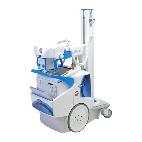
Canon OMNERA 400T Technical manual

Technical Publication:
Planning Guide
0180-095-485-EN Rev 3.1

Revision
Planning Guide 0180-095-485 OMNERA™400T
Rev. 3.1
Reason for changes Chapter Page Document Rev Datum
First release 1.1 20150318
Update according to
OMNERA, 20150327 All All All 2.1 20150409
Text corrected Alpha -
Beta.Table dimensions
updated
Compo-
nent Speci-
fication,
Technical
Specifica-
tion
6-5, 6-8,
7-3 Apha/Beta Move-
ments, Table Top 3.1 20150813

Disclaimer
The standard warranty is void if the product has been intentionally modified, or damaged by
accident, abuse or misuse. Additionally, this warranty is void if untrained personnel service
the OMNERA® 400T400A equipment.
Lost profits, downtime, goodwill, damage to or replacement of property, and any costs of
repairing the OMNERA® 400T400A resulting from a breach of warranty are not the
responsibility of Canon Medical Systems
Specifications are subject to change without notice. Not responsible for typographical errors.
Notices
No part of this publication may be reproduced, transmitted, transcribed, stored in a retrieval
system or translated into any language or computer language, in any form or by any means,
electronic, mechanical, magnetic, optical, chemical, manual or otherwise, without the prior
written permission of Canon Medical Systems
Note: Photos and drawings used in this guide may be slightly different from the
actual product.
Dispose of electronic equipment in accordance with local, state, and federal
regulations.
THIS DOCUMENT CONTAINS PROPRIETARY INFORMATION AND SUCH INFORMATION
MAY NOT BE DISCLOSED TO OTHERS FOR ANY PURPOSE NOR USED FOR
MANUFACTURING PURPOSES WITHOUT WRITTEN PERMISSION FROM CANON
MEDICAL SYSTEMS.
Trademarks
OMNERA® is a registered trademark of Canon Medical
Systems
All third-party brand names, product names, or logos
appearing in this manual are the trademarks or registered
trademarks of their respective owners.
Canon® is a registered trademark of Canon, Inc. and may
also be a registered trademark or a trademark in other
countries.

Revision
Planning Guide 0180-095-485 OMNERA™400T
Rev. 3.1

Contents
OMNERA™400T 0180-095-485 PlanningGuide
Introduction ..............................................................................1-1
Intended Use ....................................................................................................1-1
System Overview..............................................................................................1-1
Environment Specifications....................................................2-1
Placement of Non-medical Components..........................................................2-1
Room and Installation Specifications................................................................2-1
Ceiling / Floor / Wall Specifications ..................................................................2-3
Floor Specifications ..........................................................................................2-7
Wall Specifications .........................................................................................2-10
Electrical Building Installation.........................................................................2-11
Installation and Servicing Space............................................3-1
Wallstand..........................................................................................................3-1
Table...............................................................................................................3-15
Anchoring Locations ...............................................................4-1
Wallstand..........................................................................................................4-1
Table.................................................................................................................4-9
Room Layout ............................................................................5-1
Installation Proposal .........................................................................................5-1
System Connections.......................................................................................5-18
Component Specifications......................................................6-1
Ceiling Suspended X-ray Tube Support...........................................................6-1
Wall Attachment Cable Hose............................................................................6-6
Table.................................................................................................................6-7
Wallstand........................................................................................................6-10
System Cabinet ..............................................................................................6-13
Technical Specifications .........................................................7-1
System..............................................................................................................7-1
Ceiling Suspended X-ray Tube Support...........................................................7-1
Table.................................................................................................................7-3
Wallstand..........................................................................................................7-4
Transport Specifications.........................................................8-1
Crates...............................................................................................................8-1

Contents
Planning Guide 0180-095-485 OMNERA™400T

Introduction
OMNERA™400T 0180-095-485 PlanningGuide
Page 1-1
Introduction
Intended Use
The System is a stationary X-ray system intended for obtaining radiographic images of various
portions of the human body in a clinical environment.
The System is not intended for mammography.
System Overview
The Figure 1-1 shows the main parts of the System.
Figure 1-1
1. Ceiling suspended x-ray tube sup-
port3. Wallstand
2. Table 4. Cabinet
3
1
2
4

Introduction
Planning Guide 0180-095-485 OMNERA™400T
Page 1-2

Environment Specifications
OMNERA™400T 0180-095-485 PlanningGuide
Page 2-1
Environment Specifications
Placement of Non-medical Components
Non-medical components may not be placed inside the patient environment according to reg-
ulations and standards (IEC 60601-1).
The standard defines a sphere of 1.5 m around the patient as the patient environment. The
Ceiling support can be operated across the entire rail grid, i.e. the 1.5 m boundary must be
placed outside the rail grid. Also take into account the patient entries and exits and the possi-
bility for the patient to walk around in the examination room. In practice, this means that no
non-medical components can be placed inside the walls of the examination room.
Image System Computer
Image system computer used and other similar devices are normally non-medical compo-
nents. The image system computer and the including touch-screen used in the System is no
exception and may therefore not be placed inside the examination room.
Room and Installation Specifications
Wall Clearance
According to regulations and standards (IEC 60601-1), a minimum distance of 500 mm be-
tween moving motorized parts and surrounding walls, and/or permanently installed objects
must be considered when planning the room layout. Since the Ceiling suspended x-ray tube
support and the Wallstand is manually operated (except from the Z-movement of the Ceiling
suspended x-ray tube support), the clearance requirement does not apply to Table.
The table top movement can be limited to allow a smaller room size, or if objects are placed
within the 500 mm zone. The stroke is adjustable via mechanical end stops, placed on each
side of the table top.
Ceiling Height
The System has three configurations allowing a ceiling height between 2500 mm and 3050
mm.
Table 2-1
Ceiling height
(mm) Vertical column
stroke (mm) Ceiling rails
2500-2700 1450 Low ceiling rails.
2700-2850 1450 Standard ceiling rails. (Standard con-
figuration).
2850-3050 1700 Standard ceiling rails.

Environment Specifications
Planning Guide 0180-095-485 OMNERA™400T
Page 2-2
Installation Cube
If it is not possible to mount the System in the ceiling, an installation cube is needed. There are
two standard heights. For more information, please contact the Manufacturer. The ceiling
height configuration must be chosen when the System is ordered.
Table 2-2
Ceiling height (mm) Vertical column stroke
(mm) Installation cube
>2500 1450 Low ceiling
>2800 1700 Low ceiling

Environment Specifications
OMNERA™400T 0180-095-485 PlanningGuide
Page 2-3
Ceiling / Floor / Wall Specifications
The performance of the System is highly depending on the pre-installation work that has to be
done on the ceiling, floor and wall.
The Manufacturer does not take responsibility of the ceiling, floor or wall construction. The
Manufacturer recommends the ceiling, floor and wall to be leveled 1mm/m. Local regulations
and specifications must be observed.
The specifications specified in this section do not apply for risk regions for earthquakes. For
more information and specifications regarding risk assessments and calculations, please con-
tact the Manufacturer’s sales department.
Local regulations and specifications must also be observed. The forces listed in this document
are not always in correspondence to the local and/or national regulations.
Included in Shipment
•Expansion bolts (standard type) for the Table and the Wallstand.
•Expansion bolts (standard type) for the Installation cube (option).
•A drilling template for the Table and a marking template for the Wallstand.
•Spacers for the Table, Wallstand and Ceiling suspended x-ray tube support installa-
tion cube (option).
•Insulation kits for all System components.
•Mounting kit for the ceiling rail Y (Unistrut mounting brackets, etc.). See Figure 2-1.
Figure 2-1
•Mounting kit for the installation cube (wall mounting brackets, etc.) (option).
General Information Not Included in Shipment
•Appropriatesubconstruction fortheceiling rail Y,e.g.Unistrut, mustbe provided (not
included in shipment).
•Cable ducts or similar must be supplied (not included in shipment).
•Screws, bolts, or similar for mounting the cable outlet for the Ceiling support must be
supplied (not included in shipment).
•Alignment tools, such as rotating lasers or similar, must be supplied (not included in
shipment).

Environment Specifications
Planning Guide 0180-095-485 OMNERA™400T
Page 2-4
Ceiling Specifications
The Ceiling suspended x-ray tube support requires a ceiling with sufficient load capacity (not
within the scope of this document), e.g. concrete. If the ceiling construction is not sufficient, an
Installation cube solution is available.
The Installation cube solution is to be ordered as an option. The on-site subconstruction, nor-
mally consists of Unistrut rails or other comparable support profiles (not included in shipment).
The Unistrut rails are mounted directly to the ceiling. The ceiling rails Y, with a standard length
of 4000 mm, are then mounted on the Unistrut rails, see Fig. 2-2 and Fig. 2-3. The ceiling rails
Y can also be mounted directly to the ceiling, see Fig. 2-2 and Fig. 2-3. As a third option, if the
ceiling height is low (2500 mm-2700 mm), the Y rails of the Installation cube can be directly
mounted to the ceiling (must be ordered separately), see Fig. 2-2 and Fig. 2-3.
Each ceiling rail Y must have at least 5 fixation points with a suspended distance (A) that is
depending on the length of the traverse rails Y. Each fixation point must withstand a load of at
least 5kN.
At least 5 Unistrut rails, equally divided, must be used for a standard ceiling rail Y length (4000
mm). The total load each Unistrut rail must be able to withstand is minimum 7 kN. The Unistrut
fixation points shall not be placed directly under the ceiling rails Y.
The ceiling rails Y must be leveled (+/- 1 mm) over the entire grid. Spacers for leveling the rails
are included in the shipment. Also included is the cable outlet for the Ceiling suspended unit.
Manufacturer’s specifications of on-site subconstructionand the “Service and Installation Man-
ual”, included at delivery, must be observed.
Figure 2-2 Ceiling rails Y mounted on Unistrut rails.
1. Ceiling suspended unit rail (Y) 2. Unistrut rail or similar
A A A A
1
2
B

Environment Specifications
OMNERA™400T 0180-095-485 PlanningGuide
Page 2-5
Figure 2-3 Ceiling rails Y mounted directly to the ceiling.
1. Ceiling suspended unit rail (Y) 2.Fixation block
AAAA
1 2
B
0-250 0-250
B
5,5
78,6 25,7
25
Ø12,2 (2x)
50
2

Environment Specifications
Planning Guide 0180-095-485 OMNERA™400T
Page 2-6
Table 2-3
NOTE!
The Ceiling suspended unit rails shall be parallel ± 1mm.
Length traverse rail X 4000mm 3000mm 3000mm 2748mm(Low
ceiling)
Length ceiling rail Y 5000m 5000m 4000mm 3748mm
Minimum nr. of fix points
/ Y rail 6655
Measure A 850-1100mm 850-1100mm 850-1100mm 850-1100mm
Measure B 2800-3200mm 1800-2200mm 1800-2200mm 2778mm

Environment Specifications
OMNERA™400T 0180-095-485 PlanningGuide
Page 2-7
Floor Specifications
TheTable and the Wallstand mustbe installed on a solid base with sufficient load capacity (not
within scope of this document), e.g. concrete.
The floor must be able to withstand the pull forces supplied on the expansion bolts. The pull
forces for the components are listed in Table 2-4, see also Fig. 2-4 and Fig. 2-5.
The Table and the Wallstand must be leveled to 1 mm/m.
Figure 2-4 Drilling template,Table
Figure 2-5 Marking template, Wallstand (Isolation Plate)
A
D
B
C
B
CD
A

Environment Specifications
Planning Guide 0180-095-485 OMNERA™400T
Page 2-8
NOTE!
Marking template Wallstand (Isolation Plate). The Isolation plate for the Wallstand shall only
be used as a marking template and not as a drilling template, due to the large hole size.
Figure 2-6 Installation cube
3667.5
2668 122
122
A
B C
A
B C
A
B C
A
B C

Environment Specifications
OMNERA™400T 0180-095-485 PlanningGuide
Page 2-9
Table 2-4
For the Table and the Wallstand M10 expansion bolts are provided. Manufacturer specifica-
tions and the “Service and Installation manuals”, included at delivery for both components,
must be observed.
Mounting point A B C D E F
Force Table 5kN 5kN 5kN 5kN 5kN 5kN
Force Wallstand 5kN 5kN 5kN 5kN - -
Installation Cube 5kN 5kN 5 kN - - -

Environment Specifications
Planning Guide 0180-095-485 OMNERA™400T
Page 2-10
Wall Specifications
The walls are normally only used for mounting the cable outlets for the Ceiling suspended x-
ray support, the Wallstand and the System cabinet. Therefore, the only specification for the
walls, is that it must be possible to mount and secure the cable outlets. Screws, bolts or similar
for mounting the cable outlets, must be supplied (not included in shipment). The regulations
and specifications on page 2-1 must be followed.
The Installation cube shall be mounted to the wall. There are four wall fixation points, and each
fixation point must withstand a load of at least 0.5 kN. The wall attachment allows to place the
installation cube 0-1000 mm from the wall. If the distance to the wall is small, the attachment
must be shortened to a correct length. When the Installation cube is placed close to the wall,
make sure that a suitable placement of the cable outlet is possible.
Figure 2-7
750
750
750
750
Minimum distance, 0 mm
Maximum distance, 1000 mm
0.5kN
0.5kN
0.5kN
0.5kN
76
86
40
22
10.5 (2x)

Environment Specifications
OMNERA™400T 0180-095-485 PlanningGuide
Page 2-11
Electrical Building Installation
The Machinery Directive 2006/42/EC requires the System to be fitted with means to isolate it
from all energy sources.
NOTE!
When Service or Maintenance will be performed the technician shall lock the equipment from
all energy sources.
Power Ratings and Line Requirements
The System requires a three-phase electrical line with a protective earth ground (4 or 5 wires).
The transformers in the system cabinet requires a tap configuration (*1), the generator has an
automatic main line selection (no transformer tap configuration required). A disconnecting de-
vice shall be incorporated external to the equipment according to the national wiring rules.
•3 Phase VAC ±10%
•400VAC 50Hz
•400VAC with neutral 50Hz
•480VAC 60Hz
•Maximum wire gauge 4 AWG (25mm²)
•Required fuse 63A, 3-phase, b-curve
NOTE!
*1 For more information about tap configuration see Installation and Service Instructions.

Environment Specifications
Planning Guide 0180-095-485 OMNERA™400T
Page 2-12
NOTE!
(1) Thermal breaker recommended. The over-current releases values are suggested figures
only. The selected value should have current rating versus time curve characteristics, higher
thantheratingsspecified.Consultaqualifiedelectricalcontractortocomplywithlocalelectrical
by law and site electrical installation.
NOTE!
(2) Values based on standby mode for EPS RAD configurations (no continuous X-ray for Rad
High-Voltage generators).
Generator
Series and
Mains Voltage
Minimum
Recom-
mended
Mains
Discon-
nect to
Genera-
tor(15ft/5
m max)
Generator
Momen-
tary Line
Current
Minimum
Recom-
mended
Generator
Service
Rating
Minimum
Recom-
mended
Distribution
Trans-
former Rat-
ing
Minimum
Recom-
mended
Ground
Wire Size
Apparent
Mains
Resistance
50kW 400
VAC, 3p. (13.3
mm2)100A 100A 65kVa (13.3 mm2)0.17
65kW 400
VAC, 3p. (13.3
mm2)125A 100A 85kVa (13.3 mm2)0.13
80kW 400
VAC, 3p. (13.3
mm2)155A 100A 105kVa (13.3 mm2)0.10
50kW 480
VAC, 3p. (13.3
mm2)80A 100A 65kVa (13.3 mm2)0.24
65kW 480
VAC, 3p. (13.3
mm2)105A 100A 85kVa (13.3 mm2)0.19
80kW 480
VAC, 3p. (13.3
mm2)130A 100A 105kVa (13.3 mm2)0.15
Ω()
Other manuals for OMNERA 400T
1
Table of contents
Other Canon Medical Equipment manuals

Canon
Canon Omnera 500A User manual

Canon
Canon Aplio i900 User manual

Canon
Canon Aplio-i Series User manual

Canon
Canon OMNERA 400A User manual

Canon
Canon PSU-25BT User manual

Canon
Canon CXDI-1 User manual

Canon
Canon OCT-A1 User manual

Canon
Canon AX-C4343W Technical manual

Canon
Canon Aplio i600 User manual

Canon
Canon Leisegang OptiK 2 Manual
Popular Medical Equipment manuals by other brands

ResMed
ResMed Web-based Patient Monitor ResTraxx System brochure

Biosense
Biosense BREATH KETONE METER Patient guide

Orthofix
Orthofix Cervical-Stim Patient manual

MGF
MGF ASPIR Series Operating & maintenance instruction manual

Vetland
Vetland V1410 user manual

Apex Digital
Apex Digital DOMUS 3 instruction manual