F
E
G
B C
A
H
ØDN
ØDN
I
2xL
ØM
电机定子
stator
垫圈
gasket
垫片
washer
端子排
terminal block
连接头
E2VCON0000
E2VCON0000
connector
AWG 18-22
Ø4-6 mm
连接头
connector case
螺钉
screw
紧固螺丝
fastening screw
2
3
4
1
4
2
3
1
白色/White
黄色/Yellow
棕色/Brown
绿色/Green
CAREL
E2VCAB****
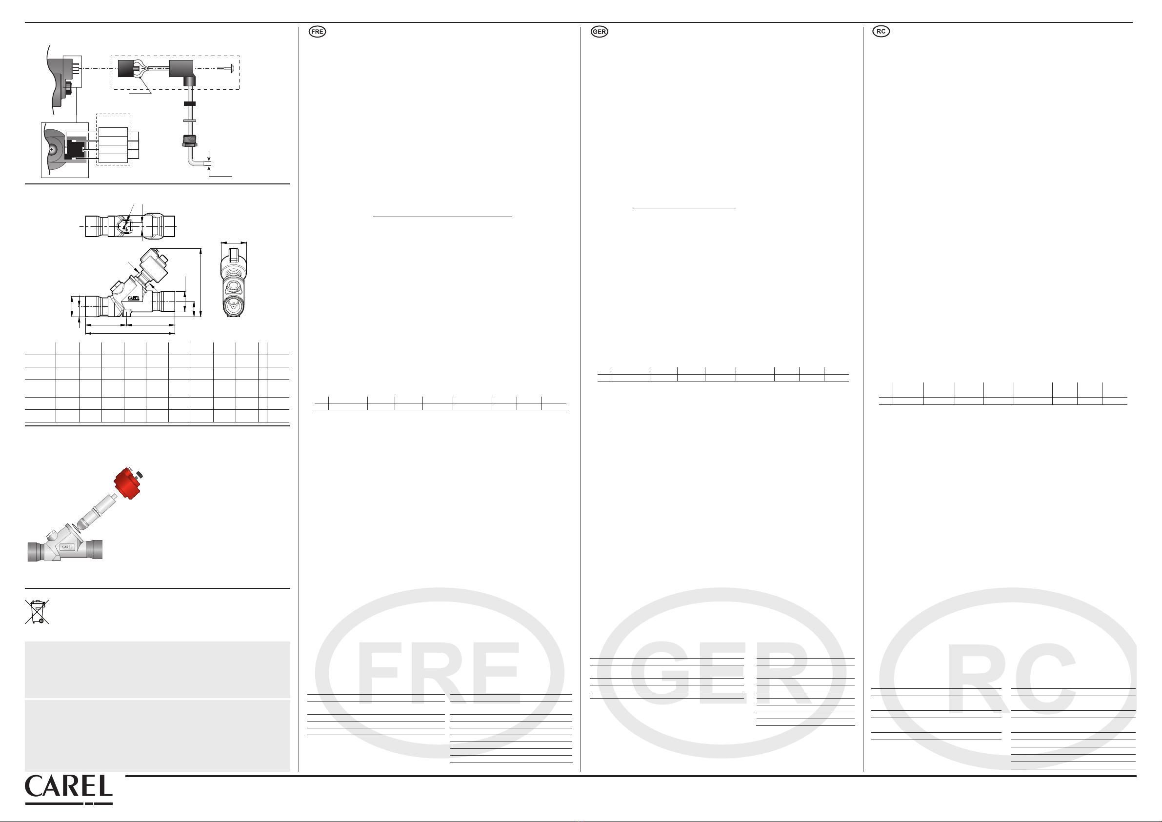
尺寸,单位为mm (inch)/ Dimensions in mm (inch)
电气连接 / Electrical connections
+05C001365 - rel. 3.0 del 28.09.2012
CAREL Industries HQs
Via dell’Industria, 11 - 35020 Brugine - Padova (Italy)
Tel. (+39) 0499716611 – Fax (+39) 0499716600 – www.carel.com – e-mail: carel@carel.com
重要说明:
CAREL的产品代表着当今的技术发展水平,随产品一同提供的技术资料中有详细的操作说明,用户也可
从www.carel.com网站下载说明(购买产品前也可下载)。
为了使特定的装置和/或设备最终能达到预期的效果,用户(设备最终的制造商、开发商或安装人)要
承担与产品配置相关的所有风险和责任。若不能按照用户手册的要求/说明完成上述各项操作,可能会
导致最终产品出现故障,这种情况下,CAREL不承担任何责任。用户只能按照有关产品的文档中描述的
方式使用本产品。CAREL的通用合同条款,在网站www.carel.com上可以获取,和/或其与客户签订的具
体协议已对CAREL就其产品应负的责任作出具体规定。
IMPORTANT WARNINGS
The CAREL product is a state-of-the-art product, whose operation is specified in the technical documentation
supplied with the product or can be downloaded, even prior to purchase, from the website www.carel.com.
The client (builder, developer or installer of the final equipment) assumes every responsibility and risk relating
to the phase of configuration the product in order to reach the expected results in relation to the specific final
installation and/or equipment. The lack of such phase of study, which is requested/indicated in the user manual,
can cause the final product to malfunction of which CAREL can not be held responsible. The final client must
use the product only in the manner described in the documentation related to the product itself. The liability of
CAREL in relation to its own product is regulated by CAREL’s general contract conditions edited on the website
www.carel.com and/or by specific agreements with clients.
Fig. 3
CAREL E5V, E6V, E7V阀的包装盒中包含了下列组件:
1. 1个套管组件(包括机械传动部件和控制杆等)
2. 1个带接头的阀体,用于和管路连接;
3. 1个树脂粘合的步进式电机,带接线柱用于连
接;
4. 1个螺纹视液镜,带2个OR垫圈;
5. 2个OR垫圈用于阀体与套管之间的密封;
6. 1个螺帽。
The packaging of the CAREL E5V, E6V, E7Vvalve contains
the following components:
1. 1 cartridge with kinematic mechanism and move-
ment (control rod);
2. 1 body with fittings to be welded to the circuit
pipework;
3. 1 resin-bonded stepper motor with connector pins;
4. 1 threaded sight glass with 2 OR;
5. 2 OR for seal seat between body and cartridge;
6. 1 threaded cap.
包装盒内包含的物件 / Contents of the packaging
废品处理
此装置(或本产品)必须按照当地废弃物品处理的强制法规,单独处理。
Disposal of the product
The appliance (or the product) must be disposed of separately in accordance with the local
waste disposal legislation in force.
一般特性
E5V, E6V, E7V是一种用于制冷系统中的膨胀节流装置(电子膨胀阀),它通过测算过热度进
行节流控制。通过安装在蒸发器出口的压力和温度传感器,电子膨胀阀可以读取温度、
压力信号,进而计算出过热度。当制冷剂充入不足或阀的下游有明显的压降时,阀的噪声可能
会提高。E5V, E6V, E7V只能和CAREL的相关设备配套使用。
请不要在正常运行条件之外使用E5V , E6V , E7V阀,如下所述。
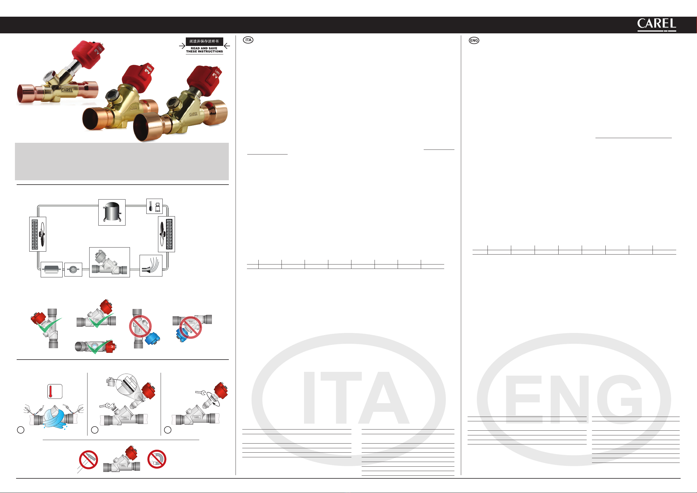
安装定位
E5V, E6V, E7V阀是双向运行的。通常在制冷剂入口之前安装一个机械式过滤器。
除了不能上下颠倒 (即电机定子朝下安装)以外,阀可以朝任何方向,如图1所示。如果在膨胀阀
前面使用截止阀,则必须设定好回路,从而防止在阀附近产生流体锤。截止阀和膨胀阀绝不能
同时关闭,以避免回路中压力过大而产生的风险。
建议E5V, E6V, E7V阀的安装位置同传统的机械式阀一样,即在蒸发器和任何分配器的之前。
温度和压力传感器(不和E5V, E6V, E7V阀一起提供)必须安装在紧邻蒸发器出口的位置,确保:
•温度传感器安装时使用了导热胶,并且能充分地与外部绝热;
•两个传感器都要安装在任何会改变压力(如阀)和/或温度(如热交换器)装置之前。
焊接和操作
E5V, E6V, E7V阀必须通过将铜制接头钎焊到冷凝器出口上(IN)和蒸发器入口管上(OUT)与回路连
接。如图2的说明:
1. 将阀体从包装盒内取出;
2. 在阀体上包一块湿布,焊接接头,不要使阀过热,如图2.1所示,瞄准火焰朝着接口,(为了
使钎焊更好,而不影响阀体与接头之间的焊接密封性,使用熔化温度低于650 °C的合金或使用
银含量超过25%的合金);
3. 当阀被冷却后,用一把口径为27mm的扳手将视液镜紧固到阀体上有特殊螺纹的槽中,确定安
装了O型密封圈(OR2081-内径为20.35mm – 厚度为1.78 mm – 材质为氯丁橡胶)来确保密封严
密。紧固视液镜直到螺纹的末端(Fig. 2.2),紧固时扭矩为30-35 Nm;
友情提示!为了确保更好的装配紧固性,使用氯丁橡胶O型圈(其它材质可能会影响装配的正
确操作),利用匹配的化学相容油,涂成一个薄层对其进行润滑。
4. 如果尚未安装,把包装盒内的O型圈用手指套入阀头(ORM 0200-20对应E5V, OR3112对应
E6V,OR3137对应E7V,材料为氯丁橡胶)。确保它是完整的、干净的,安装在密封底座的恰
当位置上(如Fig. 2.2);
5. 安装O型密封后,使用一把扳手(尺寸见图4),拧紧阀头,确保密封严实。推荐力矩:E5V, E6V
为30-35Nm或E7V为35-40Nm(如Fig. 2.3);友情提示!如果螺杆升出到管头外,请按照下列
步骤操作:
• 将螺杆紧固到管头上,电机没有被插入 -旋转直到听到滴答一声(这表明防回转的装置回
到了轴上)。
• 按照下面的指导方式(电气连接),将电机插到管头上,同时将它连接到CAREL驱动器
上;
• 以手动操作方式设定驱动器,同时设定一个数字为480步(阀完全打开);开始调步数,
螺杆将自定位到防回转导管内,以便正确安装。
6. 确保红色定子已经完全被插入到管头上,用黑色的螺帽紧紧地旋到管头上,直到橡皮圈稍稍
变形(紧固扭力为0.8Nm)(如Fig. 2.3)
7. 如图3所示,将预接线的接头连接到步进电机的槽上,紧固螺丝,扭矩大约为0.5Nm。然后将
4-pin的线连接到CAREL EVD***驱动器相对应的端口上,或其它已经被认可的CAREL控制器上,
根据下表所列出的值设定参数。
n° 类型 最少步数 最大步数 关闭步数 步/秒
速度
相电流
mA
静态相
电流
占空
比%
0 CAREL EXV 50 480 500 50 450 100 30
当关阀时,为了加快关闭速度,电子膨胀阀占空比可从30%提高到100%;要取得更快速
度,可使阀的最大励磁速度为150步/秒。
关于设定在驱动器上的参数的其它信息,请参考控制器用户手册。
不要对阀或连接管线施加扭力或变形压力。
不要用锤子或其它物品敲击阀。
不要使用可能使外部结构变形或损坏内部零件的钳子或其它工具。
不要将火焰对准阀。
不要将阀放在靠近磁场的地方。
在下列状况下,不要安装或使用阀:
• 外部结构变形或损坏;
• 发生很严重的意外事件,例如产品摔落;
• 电子部件被损坏(定子,接触运载装置,连接头等等)。
在外部结构变形或电子部件被损坏的情况下,CAREL不能保证阀的运行。
如果有灰尘,可能会使阀出现故障。
• 安装以后, 检查密封性。
• 在安装管头进入阀体之前,不要移动阀头,以避免装配不当。
• 这个阀是个承压设备,必须安装一个独立的安全压力保护系统。
• 如果超出规定的范围使用该阀,部分性能规格可能无效
• 在运行压力下,避免变形,撞击,火苗及液体腐浊。
• 当阀运行中,不要拆开阀。
• 在进行维修和拆开之前,检查没有受压液体。
电气连接
连接一个防护等级为IP67的模压好的连接头(E2VCAB****),1为绿色,2为黄色,3为棕色,4为
白色。或者,连接一根四芯线到一个防护等级为IP65的连接头(E2VCON0000),如图3所示:这
是一个标准的DIN 43650连接头。
要对E2VCON0000连接头配线,用一根外径为4~6mm的AWG18-22线,确保与线缆套管之间合适
的紧密性。
然后连接四个电机相到驱动器,E5V, E6V , E7V上的相1对应驱动器上的端口1,依次类推。
重要:相4在阀定子上标示了接地标志。
根据2004/108/EC指令和之后的修正说明,可提供一个选配的屏蔽式连接头(E2VCABS***)。
CAREL保留不预先告知即修改产品的权利。/ CAREL reserves the right to modify the features of its products without prior notice.
Fig. 5
6
3
1
5
4
2
阀类型
Type of valve DN A B C E F G H I L M
E5VA5AST00 35mm
(1,38inch)
165mm
(6,50inch)
75mm
(2,95inch)
90mm
(3,54inch)
26mm
(1,02inch)
18mm
(0,71inch)
144,1mm
(5,67inch)
26mm
(1,02inch)
12mm
(0,47inch) M5 56mm
(2,20inch)
E6VB2ASV00 42mm
(1,65inch)
195mm
(7,68inch)
89mm
(3,50inch)
106mm
(4,17inch)
33,5mm
(1,32inch)
22,5mm
(0,89inch)
149,7mm
(5,89inch)
34mm
(1,34inch)
16mm
(0,63inch) M6 56mm
(2,20inch)
E6VB2AST00 35mm
(11/8inch)
179mm
(7,05inch)
81mm
(3,19inch)
98mm
(3,86inch)
33,5mm
(1,32inch)
22,5mm
(0,89inch)
147,9mm
(5,89
inch)
34mm
(1,34inch)
16mm
(0,63inch) M6 56mm
(2,20inch)
E7VC1ASZ00 54mm
(2,13inch)
233mm
(9,17inch)
108mm
(4,25inch)
125mm
(4,92inch)
33,5mm
(1,32inch)
22,5mm
(0,89inch)
152,8mm
(6,02inch)
42mm
(1,65inch)
16mm
(0,63inch) M6 64mm
(2,52inch)
E7VC1ASX00 64mm
(2,52inch)
267mm
(10,5inch)
125mm
(4,92inch)
142mm
(5,59inch)
33,5mm
(1,32inch)
22,5mm
(0,89inch)
154,3mm
(6,07inch)
42mm
(1,65inch)
16mm
(0,63inch) M6 64mm
(2,52inch)
Fig. 4
CAREL E5V, E6V, E7V运行规格 CAREL E5V, E6V, E7V定子
兼容的制冷剂R22, R134a, R407C, R410A, R404A,
R507A, R417A
两极定子,低电压
最高运行压力(PS):高达45 bar (653 PSI) 相电流:450 mA
最大运行压差(MOPD):对于E6V & E7V为28 bar
(406 PSI);对于E5V为35 bar (508 psi)
控制频率:50 Hz (紧急关闭情况下,最大到
150 Hz)
压力设备认证:液体II组,I类 相电阻(25 °C):36 Ohm ± 10%
制冷剂温度:-40~65 °C (-40~149°F) 防护等级:带E2VCON*为IP65,带E2VCAB*
为IP67
房间温度:-30~50 °C (-22T122°F) 步距角:E5V & E6V为15°,E7V为7.5°
关于其它运行条件或可选择的制冷剂,请联
系CAREL
线性前进/线性步进式:0.03 mm (0.001 inch)
连接线:4芯(AWG 18/22)
完全关闭步数:500
控制步数:480
Caractéristiques générales
Le détendeur électronique E5V, E6V, E7V est destinée à l’installation sur des circuits frigorifiques comme détendeur d’expansion
pour le fluide réfrigérant, en utilisant comme signal de régulation la surchauffe calculée à l’aide d’une sonde de Pression et une de
Température, situées toutes les deux à la sortie de l’évaporateur. Un sous-refroidissement adapté du fluide en entrée est nécessaire pour
éviter que la vanne ne fonctionne en présence de gaz flash. Il est possible que le niveau de bruit produit par la vanne augmente lorsque
la charge de fluide frigorigène s’avère insuffisante ou en cas de fuites importantes de charge en amont de cette dernière. Pour le pilotage
des E5V, E6V, E7V on recommande d’utiliser les drivers CAREL. Ne pas utiliser les détendeurs E5V, E6V, E7V en dehors des conditions
opérationnelles reportées ci-après.
Positionnement
Le détendeur E5V, E6V, E7V est bidirectionnel. Toujours installer un filtre mécanique avant l’entrée du réfrigérant.
L’orientation dans l’espace est possible dans toutes les configurations, à l’exception de celle avec le stator dirigé vers le bas (détendeur inversé)
comme illustré en Fig. 1. En cas d’utilisation de vannes d’arrêt avant la vanne d’expansion, il faut configurer le circuit afin qu’il ne se produise
pas de coup de bélier à proximité de la vanne. Il est essentiel que la vanne d’arrêt et la vanne d’expansion ne soient jamais fermées en même
temps, afin d’éviter toute surpression dangereuse dans le circuit. La position conseillée pour le détendeur E5V, E6V, E7V est la même que le
détendeur thermostatique de type traditionnel c’est-à-dire en amont de l’évaporateur et de l’éventuel distributeur. Les capteurs de température
et de pression (non fournis avec les E5V, E6V, E7V) doivent être positionnés immédiatement en aval de l’évaporateur en ayant soin que:
•le capteur de température soit installé avec de la pâte conductrice et soit bien isolé thermiquement de l’extérieur;
•les deux capteurs soient installés AVANT d’ éventuels dispositifs qui altèrent la pression (par ex. vannes) et/ou la température (par
ex. des échangeurs).
Soudure et manipulation
Les détendeurs E5V, E6V, E7V doivent être soudés au circuit par brasage des raccords en cuivre aux tuyaux de sortie du condenseur (IN) et
d’entrée de l’évaporateur (OUT). Suivre la procédure indiquée à la Fig. 2 en procédant comme indiqué ci-après:
1. Sortir le corps du détendeur de l’emballage.
2. Enrouler le corps du détendeur dans un chiffon mouillé, et effectuer la soudure sans la surchauffer en orientant la flamme
vers l’extrémité des raccords comme à la Fig. 2.1 (pour un meilleur brasage sans altérer l’étanchéité des zones de soudure
entre le corps et les raccords utiliser un alliage à une température de fusion inférieure à 650 °C ou avec une teneur en argent
supérieure de 25%).
3. Lorsque la vanne est froide, visser le voyant de flux sur la corps de la vanne à l'intérieur du logement fileté prévu avec une clé à
fourche 27 mm en vérifiant la présence et l'intégrité du joint torique (OR2081 – diamètre interne 20,35 mm - épaisseur 1,78 mm -
matériau: Néoprène) qui garantit son étanchéité. Serrer l’indicateur jusqu’à atteindre le fin de course mécanique du filet (Fig. 2.2) avec
un couple de 30-35 Nm. Attention! Pour garantir une meilleure étanchéité de l’ensemble, nous conseillons d’utiliser des O Ring
en Néoprène (d’autres matériaux peuvent compromettre l’utilisation correcte de l’ensemble) lubrifiés avec une fine couche
d’huile compatible.
4. s’il n’était pas encore assemblé, utiliser l’O-ring présent dans l’emballage (ORM 0200-20 pour E5V, OR3112 pour E5V, OR3112 pour E6V
et OR3137 pour E7V – matériel: Néoprène) pour l’insérer avec les doigts dans le logement prévu sur la bague de la cartouche. Vérifier
l’intégrité, la propreté et la position correcte de celui-ci sur le fond du logement d’étanchéité (Fig. 2.2).
5. Visser la cartouche en acier au corps du détendeur dans son emplacement fileté spécial avec une clé à fourche (pour la dimension,
voir fig. 4) en vérifiant l’insertion correcte du joint «O’ring», qui garantit son étanchéité. Serrer la cartouche en situant la bague en
butée sur le corps vanne avec un couple de serrage conseillé de 30-35 Nm pour E5V et E6V ou de 35-40 pour E7V (Fig. 2.3).
6. Attention! Si la tige filetée sort complètement de l’emplacement de travail de la cartouche, effectuer l’opération suivante:
•Visser la tige sur la cartouche sans que le moteur ne soit inséré – faire pivoter jusqu’à ce qu’on entende un petit déclic (ceci
indique que le cadre anti-rotation est revenu dans l’axe).
•Insérer le moteur sur la cartouche (point 6-7-8) et le brancher au driver CAREL selon les instructions reportées ci-dessous
(branchements électriques).
•Mettre le Driver en fonctionnement manuel et configurer un nombre de pas égal à 480 pas (ouverture complète); faire
démarrer la séquence de pas, la tige se positionnera à l’intérieur du guidage anti-rotation pour pouvoir être installée
correctement.
7. Contrôler que le stator rouge soit inséré jusqu’à la butée de la cartouche, en vissant complètement l’écrou noir jusqu’à déformer la
couronne circulaire en caoutchouc du stator (couple de serrage 0,8 Nm). (Fig. 2 D)
8. Raccorder le connecteur déjà câblé au moteur pas à pas dans le logement correspondant et serrer la vis avec un couple de 0,5Nm en
suivant les indications de la Fig. 3. Connecter ensuite l’extrémité quadripolaire du câble aux bornes correspondantes du Driver CAREL
EVD*** ou du régulateur homologué CAREL et configurer les paramètres selon la valeur reprise au tableau ci-dessous.
n° Model Step min Step max step close Step/s speed mA pk mA hold % duty
0 CAREL EXV50 480 500 50 450 100 30
Les contrôleurs Carel pour détendeur électronique prévoient l’augmentation du cycle de fonctionnement de 30% à 100% en
phase de fermeture dans le but de diminuer les temps d’arrêt; pour accélérer davantage cette phase, il est possible de piloter
la vanne à une fréquence maximale de 150 pas/sec.Pour de plus amples informations sur les paramètres à configurer dans le
driver, se référer au mode d’emploi de contrôle (EVD4).
Ne pas exercer de torsions ou de déformations sur le détendeur ou sur les tubes de branchement.
Ne pas frapper le détendeur avec un marteau ou d’autres objets semblables.
Ne pas utiliser de pinces ou d’autres instruments qui pourraient déformer la structure externe ou endommager les organes internes.
Ne jamais orienter la flamme vers le détendeur.
Ne pas approcher d’aimants ou de champs magnétiques sur le détendeur.
Ne pas effectuer l’installation ou ne pas employer en cas de:
•déformation ou endommagement de la structure externe;
•fort impact dû par exemple à une chute;
•endommagement de la partie électrique (stator, porte contacts, connecteur,...).
CAREL ne garantit pas le fonctionnement du détendeur en cas de déformation de la structure externe ou d’endommagement
des parties électriques.
ATTENTION: La présence de particules dues à des saletés pourrait causer des dysfonctionnements de la vanne.
•Après l’installation, il faut vérifier l’étanchéité sous pression de l’assemblage.
•Ne pas enlever l’obturateur de la vanne avant d’avoir assemblé la cartouche sur le corps, ceci pourrait provoquer sa sortie du
logement et un assemblage incorrect sur le corps
•La vanne n’est pas dotée de dispositifs de limitation de la pression, l’utilisateur doit, donc, prévoir un système indépendant
de sécurité contre les surpressions.
•Une utilisation en dehors des caractéristiques peut entraîner la perte de validité des déclarations de conformité auxquelles
la vanne est soumise.
•Ne pas soumettre à des déformations, coups, flammes ou liquides corrosifs pendant l’utilisation sous pression.
•Ne pas désassemble la vanne quand elle est en fonctionnement
•Vérifier l’absence de fluide sous pression avant de procéder à toute intervention de maintenance et de démontage
Connections électriques
Connecter un connecteur moulé IP67 (E2VCAB****) dont la topographie est 1 Vert, 2 Jaune, 3 Marron, 4 Blanc. Connecter alternative-
ment un fil quadripolaire au connecteur à câbler IP65 (E2VCON0000) selon le schéma à la Fig.3: le connecteur est de type standard
DIN 43650. Pour câbler le connecteur E2VCON0000 on conseille d’utiliser des fils AWG18-22 d’un diamètre externe de 4 à 6 mm
pour permettre une prise adaptée de la garniture externe.
Successivement brancher les quatre phases moteur à votre dispositif driver de façon que la phase n°1 de la E6V, E7V corresponde à la
borne n°1 du driver et ainsi de suite. Attention: la phase n°4 est indiquée sur le stator du détendeur avec le symbole de la terre.
Des câbles blindés sont disponibles en option (E2VCABS***) pour des applications conformément à la directive 2004/108/EC et
modifications successives.
Spécifications opérationnelles CAREL E5V,
E6V, E7V
Stator CAREL E5V, E6V, E7V
Compatible avec les réfrigérants: R22, R134a, R407C, R410A, R404A,
R507A, R417A
Stator bipolaire en basse tension:
(2 phases - 24 expansions polaires)
Pression maximale de travail (PS): jusqu’à 45 bar (653 PSI) Courant de phase: 450 mA
∆P maximale de travail (MOPD): 28 bar (406 PSI) pour E6V et E7V; 35
bar (508 psi) pour E5V
Fréquence de pilotage: 50 Hz
P.E.D.: Fluid group 2, category I Résistance de phase (25 °C): 36 Ohm ± 10%
Température réfrigérante: -40T65°C (-40T149°F) Index de protection: IP65 avec E2VCON*, IP67 avec E2VCAB*
Température ambiante: -30T50°C (-22T122°F) Angle de pas: 15° pour E5V et E6V; 7,5° pour E7V;
Contacter CAREL pour des conditions opérationnelles diverses ou
réfrigérants différents.
Avancement linéaire/pas: 0,03 mm
Branchements: 4 fils (AWG 18/22)
Pas de fermeture complète: 500
Pas de réglage: 480
Allgemeine Beschreibung
Das elektronische E5V, E6V, E7V-Ventil wird in Kältekreisläufen als Kältemittelexpansionsvorrichtung installiert und
verwendet als Regelsignal die von einem Druck- und Temperaturfühler am Verdampferauslass berechnete Überhitzung.
Das Kältemittel im Einlass muss entsprechend unterkühlt werden, damit das Ventil bei Vorhandensein von Flash-Gas nicht arbeitet.
Bei unzureichender Kältemittelladung oder bei erheblichen Druckverlusten vor dem Ventil könnte sich die Geräuschentwicklung
des Ventils erhöhen. Für die Ansteuerung von E5V, E6V, E7V-Ventilen sollten nur CAREL-Geräte eingesetzt werden. Für die E5V, E6V,
E7V-Ventile sind die unten spezifizierten Betriebsbedingungen unbedingt einzuhalten.
Positionierung
Das E5V, E6V, E7V-Ventil arbeitet bidirektional. Vor dem Kältemitteleinlass muss immer ein mechanischer Filter installiert werden.
Das Ventil kann räumlich beliebig ausgerichtet werden, außer mit nach unten gerichtetem Stator (umgekehrtes Ventil), wie in Fig. 1
dargestellt. Sind vor dem Expansionsventil Absperrventile installiert, muss der Kreislauf so konfiguriert werden, dass keine Widderstöße
in Ventilnähe auftreten. Das Absperrventil und das Expansionsventil dürfen nie gleichzeitig geschlossen sein, um gefährliche Überdrük-
ke im Kreislauf zu vermeiden. Die empfohlene Position für das E5V, E6V, E7V-Ventil ist jene eines traditionellen Thermostatventils, d.
h. oberhalb des Verdampfers und eines eventuellen Verteilers. Die Temperatur- und Druckfühler (nicht im E5V, E6V, E7V-Lieferumfang
enthalten) müssen unmittelbar unterhalb des Verdampfers positioniert werden; dabei:
•ist der Temperaturfühler mit Leitmasse und angemessener thermischer Außenisolierung zu installieren;
•müssen beide Fühler VOR eventuellen druck- und/oder temperaturverändernden Aktoren (wie Ventile bzw. Wärmetauscher) installiert
werden.
Lötung und Installation
Die E5V, E6V, E7V-Ventile müssen am Kreislauf durch Verlötung der Kupferanschlüsse mit den Verflüssigerauslass- (IN) und Verdampfe-
reinlassleitungen (OUT) befestigt werden. Für die Verlötung siehe das in Fig. 2 beschriebene Verfahren:
1. Den Ventilkörper aus der Verpackung nehmen.
2. Ein feuchtes Tuch um den Ventilkörper wickeln und die Anschlüsse löten, ohne das Ventil zu überhitzen; die Flamme auf die
Anschlussenden richten (siehe Fig. 2.1); für eine bessere Verlötung ohne Beeinträchtigung der Lötstellen zwischen Körper und
Anschlüssen eine Legierung mit Schmelztemperaturen unter 650 °C oder mit Silbergehalt über 25% verwenden.
3. Bei abgekühltem Ventil das Fluss-Schauglas in die Gewindeaussparung des Ventilkörpers mit einem 27-mm-Gabelschlüssel verschrau-
ben und das Vorhandensein und die Unversehrtheit des O-Rings überprüfen (OR2081 - Innendurchmesser 20,35 mm - Dicke 1,78
mm - Material: Neopren). Das Fluss-Schauglas bis zum Gewindeendanschlag (Fig. 2.2) mit einem Drehmoment von 30-35 Nm ver-
schrauben. Achtung! Für eine bessere Abdichtung sollte der mit einem dünnen Ölfilm geschmierte Neopren-O-Ring verwendet
werden (andere Materialien könnten eine korrekte Verwendung beeinträchtigen).
4. Sollte kein O-Ring montiert sein, den im Lieferumfang enthaltenen O-Ring (ORM 0200-20 für E5V, OR3112 für E5V, OR3112 für E6V und
OR3137 für E7V – Material: Neopren) in die Aussparung des Einsatzes drücken und ihn auf seine Unversehrtheit, auf seinen sauberen
Zustand und die korrekte Position und Anhaftung am Dichtungsboden überprüfen (Fig. 2.2).
5. Den Stahleinsatz in der speziellen Gewindeaussparung des Ventilkörpers mit einem Gabelschlüssel (für die Größe siehe Fig. 4)
verschrauben; überprüfen, dass der O-Ring, der die hermetische Dichtigkeit garantiert, befestigt ist. Den Einsatz am Ventilkörper mit
einem Drehmoment von 30-35 Nm für E5V und E6V oder 35-40 für E7V festschrauben (Fig. 2.3).
6. Achtung! Sollte der Gewindeschaft völlig aus dem Einsatz heraustreten, wie folgt vorgehen:
•Den Schaft am Einsatz ohne Motor verschrauben – drehen, bis er einklickt (was bedeutet, dass die Verdrehsicherung
eingestellt ist).
•Den Motor in den Einsatz einfügen (Punkt 6-7-8) und ihn wie unten beschrieben an den CAREL-Treiber anschließen (Elek-
troanschlüsse).
•Den Treiber auf manuellen Betrieb setzen und auf 480 Stufen einstellen (vollständige Öffnung); die Stufenabfolge starten;
der Schaft positioniert sich für eine korrekte Installation in der Führung der Verdrehsicherung.
7. Überprüfen, dass der rote Stator bis zum Endanschlag in den Ventileinsatz eingefügt ist und die schwarze Mutter so fest verschrau-
ben, bis der Gummiring des Stators leicht verbogen ist (Drehmoment 0,8 Nm). (Fig. 2 D)
8. Den vorverdrahteten Steckverbinder in den Schrittmotor einfügen und die Schraube nach den Anleitungen der Fig. 3 mit rund 0,5
Nm Drehmoment festschrauben. Das Vierleiterkabelende an die entsprechenden Klemmen des CAREL-Treibers EVD*** oder an eine
andere zugelassene CAREL-Steuerung anschließen und die Parameter gemäß Parameter-Set der nachstehenden Tabelle einstellen
Nr. Modell Step min Step max step close Step/s speed mA pk mA hold % duty
0 CAREL EXV50 480 500 50 450 100 30
Die Carel-Steuerungen für das elektronische Ventil sehen die Erhöhung des Duty Cycle von 30% auf 100% in der Schließungsphase
vor, um die Stoppzeiten zu vermindern; für eine zusätzliche Beschleunigung dieser Phase kann das Ventil auf einer max. Frequenz
von 150 Stufen/Sek. gesteuert werden. Für weitere Informationen über die im Treiber einzustellenden Parameter siehe das EVD4-
Handbuch.
Das Ventil oder die Anschlussleitungen weder biegen noch verformen.
Das Ventil nicht mit Hammern oder anderem Werkzeug bearbeiten.
Keine Zangen oder anderes Werkzeug verwenden, welche die Außen- oder Innenstruktur verformen oder beschädigen könnten.
De Flamme nie direkt auf das Ventil richten.
Das Ventil nicht an Magnete oder Magnetfelder annähern.
Das Ventil in den folgenden Fällen weder installieren noch verwenden:
•bei Verformung oder Beschädigung der Außenstruktur;
•bei starken Erschütterungen, beispielsweise durch Herunterfallen;
•bei Beschädigung der elektrischen Bauteile (Stator, Kontakthalter, Steckverbinder...).
CAREL garantiert die Funktionstüchtigkeit des Ventils im Fall einer Verformung der Außenstruktur oder Beschädigung der
elektrischen Bauteile nicht.
ACHTUNG: Vorhandene Schmutzteilchen könnten Funktionsstörungen am Ventil hervorrufen.
•Nach der Installation die Druckfestigkeit der montierten Teile überprüfen.
•Den Ventilverschluss vor der Montage des Einsatzes auf dem Ventilkörper nicht bewegen, da er aus seinem Sitz austreten und
nicht korrekt montiert werden könnte.
•Das Ventil besitzt keine Überdrucksicherung; der Benutzer hat demnach für ein unabhängiges Überdrucksicherungssystem
zu sorgen.
•Eine nicht den Angaben entsprechende Verwendung würde die Gültigkeit der Konformitätserklärung des Ventils beeinträch-
tigen.
•Das Ventil unter Druck keinen Verformungen, Stößen, Flammen oder ätzenden Flüssigkeiten aussetzen.
•Da Ventil nicht auseinandernehmen, solange es in Betrieb ist.
•Vor der Wartung oder dem Ausbau des Ventils überprüfen,dass kein Kältemittel unter Druck vorhanden ist.
Elektroanschlüsse
Einen Steckverbinder für Extrembedingungen IP67 (E2VCAB****) anschließen: 1 Grün, 2 Gelbe, 3 Braun, 4 Weiß. Alternativ dazu ein
Vierleiterkabel an den Steckverbinder IP65 (E2VCON0000) gemäß Fig. 3 anschließen: Der Steckverbinder entspricht dem Standardtyp
DIN 43650. Für die Verdrahtung des Steckverbinders E2VCON0000 empfiehlt sich die Verwendung der Kabel AWG18-22 mit 4 bis 6
mm Außendurchmesser, um die Dichtung der Kabelverschraubung zu gewährleisten.
Anschließend die vier Motorphasen an den Treiber so anschließen, dass die Phase 1 des E6V, E7V der Klemme 1 des Treibers etc.
entspricht. Achtung: Die Phase 4 ist auf dem Ventilstator mit dem Erdsymbol gekennzeichnet.
Es sind optionale Kabel mit Schirm (E2VCABS***) für Anwendungen gemäß Richtlinie 2004/108/EG in geltender Fassung erhältlich.
Betriebsspezifikationen für CAREL E5V, E6V, E7V CAREL E5V, E6V, E7V-Stator
Kompatibel mit den Kältemitteln: R22, R134a, R407C, R410A, R404A, R507A, R417A Bipolarer Stator mit Niederspannung
Max. Betriebsdruck (PS): bis zu 45 bar (653 PSI) Phasenstrom: 450 mA
Max. Betriebs-∆P (MOPD):
28 bar (406 PSI) für E6V und E7V; 35 bar (508 psi) für E5V
Steuerfrequenz:
50 Hz (bis zu 150 Hz im Fall der Notschließung)
P.E.D.: Fluid group 2, category I Phasenwiderstand: (25 °C) 36 Ohm ± 10%
Kältemitteltemperatur: -40T65°C (-40T149°F) Schutzart: IP65 mit E2VCON*, IP67 mit E2VCAB*
Raumtemperatur: -30T50°C (-22T122°F) Schrittwinkel: 15° für E5V und E6V; 7,5° für E7V;
Für andere Betriebsbedingungen oder alternative
Kältemittel CAREL kontaktieren.
Linearer Vorschub/Schritt: 0,03 mm (0,001 inches)
Anschlüsse: 4 Drähte (AWG 18/22)
Stufen für vollständige Schließung: 500
Regelstufen: 480