manuals.online logo
Brands
  1. Home
  2. •
  3. Brands
  4. •
  5. Carel
  6. •
  7. Controllers
  8. •
  9. Carel FCS Series User manual

Carel FCS Series User manual

FCS series single phase fan speed controller / Однофазные регуляторы скорости вентиляторов серии FCS
+050004078 - rel. 1.2 del 20.07.2007
Model
Модель
A (lcomponent side)
А (со стороны компонентов)
B
B
C
C
D
D
E
E
FCSM 0423*0 75 100 40 82 107
FCSM 0823*0 75 100 58 82 107
FCSM 1223*0 75 100 58 82 107
Dimensions (mm) / Размеры (мм)
Fig. 1
A
D
A
D
B E
E
B
C
C
4 A
8 e 12 A
General characteristics
The single-phase FCS units are electronic voltage regulators that use the phase-control
principle to regulate the output voltage supplied to the load, according to a control
signal input.
The controllers are used to control asynchronous motors, such as fans, pumps, mixers,
stirrers, etc. By applying a 0 to 10 Vdc control signal, the effective voltage provided to the
load varies from 0 to 230 Vac.
The board also features, at the terminal marked +V, a non-stabilised power source, 20
Vdc 40 mA, which can be used to create a manual control signal using a 10 kOhm
potentiometer. The controllers are protected against short-circuits by a fuse on the
outside of the board, for easy access and, where necessary, replacement (see Table 2
for the values). Check that the motors used are suitable for phase control applications.
Assembling the controller in the panel
The controller is mounted using plastic spacers (supplied), to be inserted in the four
holes on the board. To optimise the dissipation of the heat produced, the device should
be installed in environments where the temperature does not exceed 50 °C and there is
sufficient air circulation.
The 8/12 A models should be installed in such a way that the fins on the heat sink are
arranged vertically (see Fig. 2).
The installer must guarantee the safety of the device.
Electrical connections
The speed controller must be connected to the control device as follows:
• Install a safety disconnecting switch upstream on the supply line (230 Vac) so as to be
able to isolate the device for inspection.
• Connect the power supply (230 Vac) to terminals L and N. Connect the fan motor to
the terminals marked LOAD.
• Before powering up the controller, check the power connections and in 8/12 A devices,
make sure the earth connection is correct.
• For the power connections and the earth wire, use cables with the cross-section shown
in the table of technical specifications (Table 1).
• For the control signal, keep the cable separate from other power cables.
Commissioning
After having checked the connections, power up the board and apply a 0 to 10 Vdc input
signal.
When the control signal changes the effective voltage at the controller output will vary
from 0 to 230 V.
In the case of resistive loads and a mains frequency of 50 Hz, the input/output
characteristic is shown in Fig. 3: the x-coordinate shows the control voltage, while the
y-coordinate indicates the effective voltage supplied at the output to the load.
Основные характеристики
Однофазный контроллер FCS это электронный регулятор напряжения с
использованием принципа контроля фаз и регулированием выходного
напряжения в зависимости от входящего сигнала. Контроллер
используется для управления асинхронными двигателями, такими как
вентиляторы, насосы,смесители, мешалки и т.д. При помощи входящего
сигнала от 0 до 10В выходное напряжение регулируется в диапазоне от
0 до 230В. Также на плате контроллера есть источник питания 20В 40мА
на клемме +V, который может быть использован для ручного управления,
при помощи переменного резистора 10кОм.Контроллер должен
быть защищен от короткого замыкания внешним предохранителем,
с возможностью свободного доступа для обслуживания или замены
в случае необходимости (см Таб.2 для подбора). Убедитесь что
используемый электродвигатель подходит для фазового регулирования.
Монтаж контроллера в панель
Контроллер устанавливается при помощи пластиковых держателей,
устанавливаемых в отверстия на плате.Для обеспечения
оптимальных условий работы контроллера необходимо обеспечить
беспрепятственную циркуляцию воздуха и температуру не более 50ºС.
Модели 8/12А необходимо устанавливать так чтобы ребра радиатора
охлаждения были направлены вертикально( см. Рис.2). Установщик
должен гарантировать защиту контроллера
Электрические подключения
Регулятор скорости вращения должен быть подключен к устройствам
контроля следующим образом:

установите предохранительный выключатель не линии подачи
напряжения питания (230В), для обеспечения возможности отключения
контроллера для проверки.

присоедините напряжение питания (230В) на клеммы L и N.
Присоедините двигатель вентилятора на клеммы LOAD.

перед включением проверьте правильность подключения силовых
соединений для контроллеров 8/12А, а также правильность
подключения заземления.

для силовых соединений и заземления используйте кабель сечением
согласно таблице в технических характеристик (таб. 1)

сигнальный кабель необходимо прокладывать отдельно от силовых.
Ввод в эксплуатацию
После проверки подключения, включите напряжение питания и 0 10В
сигнал управления.
При изменении контрольного сигнала напряжение на выходе
контроллера изменяется от 0 до 230В.
При резистивной нагрузке и частоте 50Гц характеристики входа/выхода
будут соответствовать рис.3: где: ось х – напряжение управления и ось у –
напряжение подаваемое на потребителя.
CAREL S.p.A.
Via dell’Industria, 11 - 35020 Brugine - Padova (Italy)
Tel. (+39) 0499716611 – Fax (+39) 0499716600 http://www.carel.com – e-mail: [email protected]
+050004078 - rel. 1.2 del 20.07.2007
LOADNLLOADNL
+V
M
230 Vac
LINEA
LINE
LINEA
LINE
0...10 Vdc
Segnale di comando
Driving signal
Segnale di comando
Driving signal
+-
4A
M
230 Vac
+V
0...10 Vdc
+-
Pilotaggio con potenziometro
Driven by potentiometer
+
+V
10KΩ
8 e 12 A
Electrical connections / Электрические подключения
Fig. 2
0
1
23
4
5
6
7
8
9
10
50
100
150
200
250
VAC OUT [V]
Vdc 0-10
Vac 0-230
FCSM**2300
FCSM**23L0
/Input/output characteristic / Характеристики входа/выхода.
Fig. 3
Technical specifications
Single-phase supply 230V +10%/-15%
Frequency 50/60Hz
Control signal 0 to 10Vdc
Power supply for possible manual control (+V terminal) 20 Vdc 40 mA
Operating temperature -10T50°C
Storage temperature -20T70°C
Input impedance 10 k
Type of the action-disconnection 1Y
Index of protection IP00 (open board)
Pollution of the control device II
Category of protection against voltage surges III
Period of electrical stress across the insulating parts Long
Min cross-section of the connection cables
4/8 A device
12 A device
Note: if using the controller at maximum operating temperature and full
load, use cables with maximum operating temperature at least 105 °C
1.5 mm2
2.5 mm2
Tab. 1
Note: for the 12 A device, use a shielded cable with the shield connected to earth on the
board side.
Insulation characteristics
• 3750 Vac between the control signal input and the live parts of the device
• 1250 Vac between the earth and the live parts of the device for 8 A and 12 A models
The 4 A device is suitable for installation in class I and II appliances.
The 8 A and 12 A devices are suitable for installation in class I appliances.
Model Rated
current [A]
Peak
current [A]
Max current [A] Fuses
FCSM0423*0 4 4 x r. current r. current +10% Ceramic 5x20 5 A T.
FCSM0823*0 8 3 x r. current r. current +10% Ceramic 6.3x32 8 A T.
FCSM1223*0 12 3 x r. current r. current +10% Ceramic 6.3x32 12 A T.
Tab. 2
All models have the CE mark and comply with the EEC directives 72/23, 89/336 and
subsequent updates, based on the standards: EN 55014-1; EN 55014-2; EN 61000-6-1;
EN 61000-6-2; EN 61000-6-3; EN 61000-6-4; EN 60730-1; EN 61010-1.
Warning: mains voltage on board.
Disposal of the product
The appliance (or the product) must be disposed of separately in accordance with the local waste
disposal legislation in force
IMPORTANT WARNINGS
The CAREL product is a state-of-the-art device, whose operation is specified in the technical docu-
mentation supplied with the product or can be downloaded, even prior to purchase, from the website
www.carel.com. The customer (manufacturer, developer or installer of the final equipment) accepts
all liability and risk relating to the configuration of the product in order to reach the expected results
in relation to the specific final installation and/or equipment. The failure to complete such phase,
which is required/indicated in the user manual, may cause the final product to malfunction; CAREL
accepts no liability in such cases. The customer must use the product only in the manner described
in the documentation relating to the product. The liability of CAREL in relation to its products is
specified in the CAREL general contract conditions, available on the website www.carel.com and/or
by specific agreements with customers.
Технические характеристики.
Напряжение питания однофазное
230V +10%/-15%
Частота 50Гц
Напряжение питания для ручного управления (клемма+V) ±20В 40мА
Рабочая температура -10..+50°С
Температура хранения
-20 +70°C
Входное сопротивление 10кОм
Тип действия отключения
1Y
Индекс защиты IP00 (без корпуса)
Опасность для окружающей среды
II
Категория защиты от перенапряжений
III
Период сопротивления изоляции Длительный
Минимальное сечение соединительного кабеля
4/8 A
контроллер
12 A
контроллер
Примечание: при использовании контроллера при
максимальной окружающей температуре и полной нагрузке
используйте кабель с максимальной рабочей температурой не
менее 105ºС
1.5 mm2
2.5 mm2
Таб.1
Примечание: для 12 А контроллера используйте экранированный кабель
с присоединением заземления на плате контроллера.
Характеристики изоляции
• 3750 Vac между входом сигнала регулирования и силовыми
компонентами контроллера
• 1250 Vac между «землей» и силовыми компонентами контроллера для
моделей 8А и 12А.
Контроллер 4 А предназначен для оборудования I и II класса.
Контроллеры 8А и 12А предназначены для оборудования II класса.
Модель Рабочий
ток(А)
Пиковый
ток (А)
Максимальный
рабочмй ток (А)
Предохранители
FCSM0423*0 4 4 x r.
кратный рабочий
+ 10 %
керамический
5x20 5 A T.
FCSM0823*0 8 3 x r.
кратный рабочий
+10%
керамический
6.3x32 8 A T.
FCSM1223*0 12 3 x r.
кратный рабочий
+10%
керамический
c 6.3x32 12 A T.
Таб.2
Вск модели имеют маркировку СЕ и соответствуют директивам электробезопасности
72/23, 89/336 и последующие обновления базирующиеся на стандартах EN 55014-1, EN
55014-2, EN 61000-6-1, EN 61000-6-2, EN 61000-6-3, EN 61000-6-4, EN 60730-1, EN 61010-1.
Внимание: высокое напряжение
Утилизация продукта: Контроллер (или изделие) должен утилизироваться
раздельно, в соответствии с
ВНИМАНИЕ: ВАЖНО - Продукция CAREL это современное устройство, описание и
техническая документация к которому прилагается или может быть скачана с сайта www.
carel.com . Заказчик (разработчик , распространитель или установщик оборудования)
берет на себя всю ответственность и риск относительно конфигурации продукта
для достижения предусмотренных результатов и/или специфичных использований.
Упущение данной фазы которая требует/указана в руководстве по эксплуатации может
привести к сбоям в работе оборудования в целом, за которые CAREL не несет никакой
ответственности. Заказчик должен использовать устройство только в соответствии с
технической документацией к данному продукту.
Ответственность CAREL по отношению к своему продукту определена общими
условиями договора CAREL, доступных на сайте www.carel.com и/или специфичными
соглашениями с клиентами.
Питание Питание
/ Нагрузка
управляющий сигнал управляющий сигнал
управление при помощи переменного резистора

This manual suits for next models

3

Other Carel Controllers manuals

Carel mboss Manual

Carel

Carel mboss Manual

Carel PJEZ G Series User manual

Carel

Carel PJEZ G Series User manual

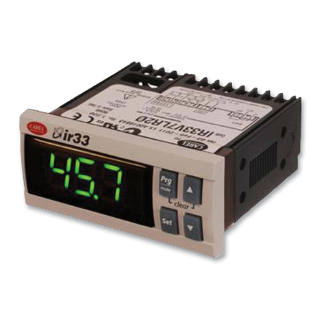
Carel ir33 platform User manual

Carel

Carel ir33 platform User manual

Carel IRMPX00000 User manual

Carel

Carel IRMPX00000 User manual

Carel ADCD000110 User manual

Carel

Carel ADCD000110 User manual

Carel DN33 Universale Series User manual

Carel

Carel DN33 Universale Series User manual

Carel ir33+wide User manual

Carel

Carel ir33+wide User manual

Carel IR32M User manual

Carel

Carel IR32M User manual

Carel WS01H02M20 User manual

Carel

Carel WS01H02M20 User manual

Carel EASY FREEZE PZD C0 Series User manual

Carel

Carel EASY FREEZE PZD C0 Series User manual

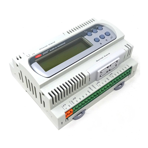
Carel pCO User manual

Carel

Carel pCO User manual

Carel pCO1 series User manual

Carel

Carel pCO1 series User manual

Carel AT th Tune Series User manual

Carel

Carel AT th Tune Series User manual

Carel e-drofan User manual

Carel

Carel e-drofan User manual

Carel PJEZ Series User manual

Carel

Carel PJEZ Series User manual

Carel pCO3 series User manual

Carel

Carel pCO3 series User manual

Carel PlantWatchPRO PV3W User manual

Carel

Carel PlantWatchPRO PV3W User manual

Carel PSOPZKEY00/A0 User manual

Carel

Carel PSOPZKEY00/A0 User manual

Carel ir33 smart User manual

Carel

Carel ir33 smart User manual

Carel AT-th Tune Series User manual

Carel

Carel AT-th Tune Series User manual

Carel pRack pR300 User manual

Carel

Carel pRack pR300 User manual

Carel pCO2 Series User manual

Carel

Carel pCO2 Series User manual

Carel boss Series User manual

Carel

Carel boss Series User manual

Carel thTx User manual

Carel

Carel thTx User manual

Popular Controllers manuals by other brands

Siemens Acvatix SAX61 MO Series Basic documentation

Siemens

Siemens Acvatix SAX61 MO Series Basic documentation

Barco EC Series Safety guide

Barco

Barco EC Series Safety guide

MOULDPRO Flosense 3.0 user guide

MOULDPRO

MOULDPRO Flosense 3.0 user guide

Danfoss AMV 335 installation guide

Danfoss

Danfoss AMV 335 installation guide

Savant SmartControl SSC-W02R Quick reference guide

Savant

Savant SmartControl SSC-W02R Quick reference guide

Lexicon DC-1 Owner's manual addendum

Lexicon

Lexicon DC-1 Owner's manual addendum

Planar DOME Md4/PCV installation guide

Planar

Planar DOME Md4/PCV installation guide

Eaton S611 user manual

Eaton

Eaton S611 user manual

AGNEUS AGCD840V20L user manual

AGNEUS

AGNEUS AGCD840V20L user manual

fakro ZWG3 user manual

fakro

fakro ZWG3 user manual

Surefire BMS-300 Installation & operation manual

Surefire

Surefire BMS-300 Installation & operation manual

Dometic Go Power! GP-PC Series user manual

Dometic

Dometic Go Power! GP-PC Series user manual

ECTIVE SC 20 operating instructions

ECTIVE

ECTIVE SC 20 operating instructions

GE PACSystems* RX3i Command Line Interface Manual

GE

GE PACSystems* RX3i Command Line Interface Manual

Würth Proteus-III How-to

Würth

Würth Proteus-III How-to

Omron Trajexia TJ1-DRT Hardware reference manual

Omron

Omron Trajexia TJ1-DRT Hardware reference manual

Klockner Moeller SUCOS PS 316 installation instructions

Klockner Moeller

Klockner Moeller SUCOS PS 316 installation instructions

Datakom DKG-209 user manual

Datakom

Datakom DKG-209 user manual

manuals.online logo
manuals.online logoBrands
  • About & Mission
  • Contact us
  • Privacy Policy
  • Terms and Conditions

Copyright 2025 Manuals.Online. All Rights Reserved.