manuals.online logo
Brands
  1. Home
  2. •
  3. Brands
  4. •
  5. Carrier
  6. •
  7. Security Sensor
  8. •
  9. Carrier 7C-SE-C1X-DT User manual

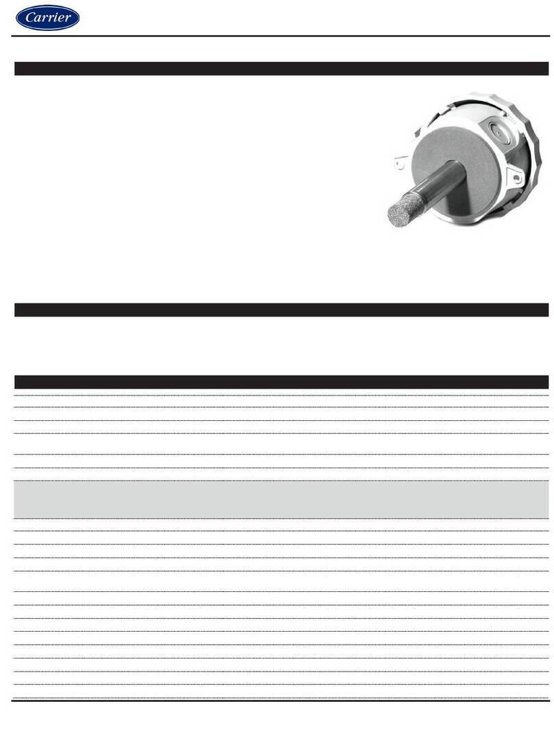
Carrier 7C-SE-C1X-DT User manual

For more information, contact your local Carrier Controls Expert
©2023 Carrier. All Rights Reserved. Cat. No. 11-808-964-01
INTRODUCTION
The Duct Sensor provides a high precision temperature and humidity sensor that is pre calibrated
from the factory to a Node or Stat. The Duct Sensor is easily mounted on a duct with the help of self-
tapping screws. The Duct Sensor uses a proprietary 1-wire protocol to communicate with a master
device such as a SmartNode.
PACKAGE CONTENTS
•Duct sensor
•Mounting accessories
•One Sensor bus cable of 20ft length
•Modular pipes (100 and 150mm) to allow the air.
in the duct to be pitot.
SPECIFICATIONS
Power
3-wire interface powered at 3.3V with
maximum current limit of 10mA
Accuracy
Temperature (typical +/- 1°F (0.5C),
Humidity (typical +/- 2% RH),
Protection
Protection: IP 20, NEMA Type 1
Pollution grade: 2
Certification: ROHS
Communication
3 wire sensor bus for daisy chained
sensor communication and low power 3V
DC.
Operating temperature
Operating Environment: 0°F (-17°C) – 122°F
(50°C)
Span shift due to temperature variation
< 0.5% of reading per 10°C
Mounting
Firmly on the Duct. Torque not exceeding
0.2Nm to be used to fix the device. Drill a
17dia hole for the pipe to pitot the air
stream for measurement.
Storage temperature
15°F (-10°C) to 150°F (70 °C)
INSTALLATION GUIDE
Duct Sensor
(7C-SE-C1X-DT)
Scan this QR
code to get a
more detailed
version of the
Installation
Guide
For more information, contact your local Carrier Controls Expert
©2023 Carrier. All Rights Reserved. Cat. No. 11-808-964-01
_ag‘ f[‘ X
1. Drill a hole of dia greater than 18mm for the pipe to enter the Duct. Mount the Duct Sensor
using two #8-1.5” self-tapping screws as shown in Figure 1. The transmitter must be
installed vertically with the air inlet pipe pointing perpendicular to the duct.
Figure 1
2. Choose the length of the pipe as per the duct dimension. The lengths of the pipes
provided are 100 and 150mm long. There is an end cap provided to make the air pitot
towards the sensor. Refer Figure 2. To lock and unlock the tubes.
Align the arrow on the pipe to the lock
symbol and rotate clockwise to secure the position
Rotate the pipes anti-clockwise to separate them.
Figure 2
PRECAUTIONS
•Failure to wire devices with the correct polarity when using a shared transformer may
result in damage to any device powered by the shared transformer.
•Mount the tubing so that the tube is in direct line of a breeze or draft.
•Turn off the power before wiring. Never connect or disconnect the wiring with the
power turned on. Do NOT allow live wires to touch the circuit boards.
•Install in accordance with all state and local codes.
For more information, contact your local Carrier Controls Expert
©2023 Carrier. All Rights Reserved. Cat. No. 11-808-964-01
i [d[‘ X
1. Turn the power OFF. Connect one end of the Sensor Bus cable to one end of the RTS
port on the Smart Node and the other end to the IN port of the Duct Sensor as shown in
Figure 3. Set the Daisy chain switch to NO position if there is only one Duct Sensor
connected.
Set the switch to No
Smart Node
Sensor Bus
Figure 3
2. Power to the Duct Sensor is provided through this cable; no external power wiring is
required. If an additional Duct sensor needs to be connected, connect the other Sensor
Bus cable to one end of the OUT port of the Duct Sensor and the other end to the IN port
on the Duct Sensor. See Figure 4 for connections.
3. To set addresses on the Duct Sensor, open the top cover and find the rotary address
setting switch on the PCB. The position is marked from 0 to 3. Available addresses on the
Duct Sensor are 0, 1 and 2. Address 3 is not available for Daisy chain.
Address setting switch
4. To enable Multiple Duct Sensor communication, the
Daisy Chain
switch must be set to
Yes
. When there is no requirement for additional sensors to be connected to the OUT
port of the DPS, the
Daisy Chain
switch must be set to
No
. See Figure 4.
Set the switch to Yes Set the switch to Yes Set the switch to No
Smart Node
Sensor BusSensor BusSensor Bus
Figure 4
For more information, contact your local Carrier Controls Expert
©2023 Carrier. All Rights Reserved. Cat. No. 11-808-964-01
CARRIER CLIMAVISION TECHNICAL SUPPORT
Installation and servicing of Control Systems can be hazardous due to electrical
components. Only trained and qualified service personnel should install, repair or service
control system components.
For more information on wiring, commissioning, or usage of the ClimaVision product line,
please refer to any documentation provided with the job. If no documentation was provided
with the job, please use the ClimaVision Help Center (support.climavision.com) where you
can find application specific wiring schematics and helpful user guides and videos or scan
the QR code here:
If you need help beyond that, please reach out to your local Carrier distributor for support.
Scan this QR code to
get a more detailed
version of the
Installation Guide

Other Carrier Security Sensor manuals

Carrier Graviner Mk7 Configuration guide

Carrier

Carrier Graviner Mk7 Configuration guide

Carrier NSB-NO2-V-BB User manual

Carrier

Carrier NSB-NO2-V-BB User manual

Carrier SPS User manual

Carrier

Carrier SPS User manual

Carrier Graviner Mk6 Configuration guide

Carrier

Carrier Graviner Mk6 Configuration guide

Carrier 7C-SE-C72X-X Datasheet

Carrier

Carrier 7C-SE-C72X-X Datasheet

Carrier Graviner Mk6 User manual

Carrier

Carrier Graviner Mk6 User manual

Carrier Graviner Mk7 User manual

Carrier

Carrier Graviner Mk7 User manual

Carrier ARITECH VE1012PI Assembly instructions

Carrier

Carrier ARITECH VE1012PI Assembly instructions

Carrier NSB-LDT4-PS-BB Guide

Carrier

Carrier NSB-LDT4-PS-BB Guide

Carrier 7C-SE-C68 Series User manual

Carrier

Carrier 7C-SE-C68 Series User manual
Carrier BN Series User manual

Carrier

Carrier BN Series User manual

Carrier HyperSense 7C-HS-C1W-X User manual

Carrier

Carrier HyperSense 7C-HS-C1W-X User manual

Carrier Aritech 6933AMP Assembly instructions
Carrier

Carrier Aritech 6933AMP Assembly instructions

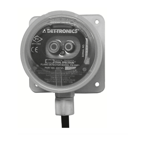
Carrier DET-TRONICS Dual Spectrum PM-5MPX User manual
Carrier

Carrier DET-TRONICS Dual Spectrum PM-5MPX User manual

Carrier KIDDE 60WLDR-W User manual

Carrier

Carrier KIDDE 60WLDR-W User manual

Popular Security Sensor manuals by other brands

SGB DLR-GS Documentation

SGB

SGB DLR-GS Documentation

LCN LCN-GBL installation guide

LCN

LCN LCN-GBL installation guide

CARLO GAVAZZI Guardian 1 Original user manual

CARLO GAVAZZI

CARLO GAVAZZI Guardian 1 Original user manual

Milwaukee 48-35-1211 Operator's manual

Milwaukee

Milwaukee 48-35-1211 Operator's manual

AMS TCS3720 quick start guide

AMS

AMS TCS3720 quick start guide

Texecom Prestige DT installation instructions

Texecom

Texecom Prestige DT installation instructions

Zeiss 4QBSD instruction manual

Zeiss

Zeiss 4QBSD instruction manual

DMP Electronics 1127W installation guide

DMP Electronics

DMP Electronics 1127W installation guide

SONBEST SM1911M user manual

SONBEST

SONBEST SM1911M user manual

CDP CDP-001F manual

CDP

CDP CDP-001F manual

HME VDB102C installation guide

HME

HME VDB102C installation guide

ESYLUX RC 130i Installation and operating instructions

ESYLUX

ESYLUX RC 130i Installation and operating instructions

Monitor Technologies DustAlarm ES Installation & operation

Monitor Technologies

Monitor Technologies DustAlarm ES Installation & operation

PCB Piezotronics 117B31 Installation and operating manual

PCB Piezotronics

PCB Piezotronics 117B31 Installation and operating manual

iRay Technology Venu 1012X Calibration guide

iRay Technology

iRay Technology Venu 1012X Calibration guide

LUXOMAT PD4-M-DALI/DSI-1C-FC Installation and operating instruction

LUXOMAT

LUXOMAT PD4-M-DALI/DSI-1C-FC Installation and operating instruction

Rosslare SA-01P installation manual

Rosslare

Rosslare SA-01P installation manual

BEMKO SES05WH user manual

BEMKO

BEMKO SES05WH user manual

manuals.online logo
manuals.online logoBrands
  • About & Mission
  • Contact us
  • Privacy Policy
  • Terms and Conditions

Copyright 2025 Manuals.Online. All Rights Reserved.