Carrier Graviner Mk6 Configuration guide

OMD Technical Note TN20005
Carrier Fire & Security
8 Newmarket Court, Page 1 of 11
Chippenham Drive,
Kingston, Milton Keynes, MK10 0AQ
Business Confidential
Graviner Mk6 Oil Mist System Detector Head
Inspection & Cleaning Process
Introduction
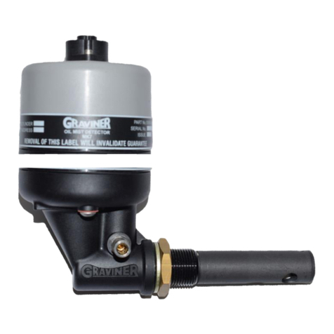
The Graviner OMD Detector is made of 2 assemblies, the Detector Head and the Detector
Base. The Detector Head is attached to the Detector Base with 2 Allen bolts.
The oil mist detection chamber in each Detector Head must be inspected at regular intervals
and cleaned to remove any buildup of oil splash or carbon deposits created by the operation
of the engine.
Our experience indicates that the cleaning interval will be unique to each engine and
dependant upon many factors such as the way the vessel engine is operated, the engine
temperature, the condition of the engine oil and the engine service intervals.
This Technical Note describes the tools required and the cleaning procedure to be used to
inspect and clean the Mk6 Detector.
As required by IACS M67 Graviner Mk6 OMD systems will automatically warn the Users
when the detection window becomes partially obscured and must be cleaned. Graviner
recommend establishing a cleaning and maintenance regime to minimise any Fault message
warnings of this type and maximise the service life of each Detector Head.
As a guide, the Detector Head should be cleaned and inspected every 6 months and the
sample pipe in the Detector Base cleaned and inspected every 12 months.
Detector Head
Detector Base
Detector Sample Pipe

OMD Technical Note TN20005
Carrier Fire & Security
8 Newmarket Court, Page 2 of 11
Chippenham Drive,
Kingston, Milton Keynes, MK10 0AQ
Business Confidential
Graviner recommend that the Detector Base and sample pipe are blown through with Clean
Air to remove any potential blockages as shown in the image below.
Clean Air at a working pressure of up to 90 PSI should be used.
WARNING - Do NOT remove the Detector Base from the engine crankcase
whilst the engine is in operation.
This action should be carried out whilst the engine is stopped to avoid the
possibility of hot oil coming out of the Detector Base.
Please Note
Graviner Detector Heads should only be cleaned with the recommended cleaning fluid and
cleaning buds.
Many cleaning fluids have been evaluated by Graviner the Electrolube ASC fluid is
recommended by Graviner as our tests have shown it offers the best cleaning ability and
leaves no residue on the glass chamber.
(Note: Do not use any third party electronic contact cleaners, isopropyl alcohols, flux
removers, any harsh chemical cleaners, etc., as these will affect the Detector
performance.
Only use the official Graviner Cleaning products).
These items are included in the Graviner Service Kit (D9221-027), see contents list below:-
(The items are also available from Graviner as individual parts).

OMD Technical Note TN20005
Carrier Fire & Security
8 Newmarket Court, Page 3 of 11
Chippenham Drive,
Kingston, Milton Keynes, MK10 0AQ
Business Confidential
Service Kit (part number) D9221-027 consists of:
Description
Part No
Qty
Category
Fan Retainer
1-B3741-902
5
Spares
Compression Spring
1-B3721-006
5
Spares
Base Moulding Seal
1-C1513-802
5
Spares
Fan Connector Seal (1 Screw)
1-C1413-801
5
Spares
Fan Connector Seal (2 Screw)
1-35134-K037
5
Spares
M3 Screw
1-21833-H01
5
Spares
Glass Cleaner
1-A7311-002
1
Consumables
Foam Buds –Packet of 25pcs
1-B6910-217
2
Consumables
4mm Hexagon Key
1-B691 0-219
2
Tools
Pulling Tool
1-D9131-002
1
Tools
Materials Safety Data Sheet
-
2
Information

OMD Technical Note TN20005
Carrier Fire & Security
8 Newmarket Court, Page 4 of 11
Chippenham Drive,
Kingston, Milton Keynes, MK10 0AQ
Business Confidential
Cleaning the Detector
1. Inspect the contents of the Mk6 Event log.
It is important to check the contents of the Mk6 Event log as it may show Fault messages
which indicate the condition of a defined Detector.
On the Control Panel select Main Menu > 1. User > 3. Event Log > 1. List All Events
Using the up and down arrow keys scroll through the recent events. An LED Average Fault or
Detector Fault message is typically an indication that the Detector is contaminated by oil and
should be cleaned.
2. Check the Status of each Detector prior to any cleaning taking place.
On the Control Panel select Main Menu > 1. User > 1. System Status > 2. Detector > 2.
Detector Status. Select the required Engine and Detector to access the Detector Status
Screen.
Ensure:-
The Alarm settings are correct,
The Detector is NOT Isolated,
On the Control Panel select Main Menu > 1. User > 1. System Status > 2. Detector > 3.
Detector Faults. Select the required Engine and Detector to access the Detector Fault Status
Screen.

OMD Technical Note TN20005
Carrier Fire & Security
8 Newmarket Court, Page 5 of 11
Chippenham Drive,
Kingston, Milton Keynes, MK10 0AQ
Business Confidential
Ensure:-
There are NO active Faults shown.
If any Faults are indicated please take appropriate actions to clear the indication(s).
3. If safe to do so, power down the OMD system or Isolate the Detector as described in the
Mk6 OMD system Installation, Operation & Maintenance (IOM) Manual.
4. Disconnect the cable connector fitted to the top of the Detector Head.
5. Using a 4mm hexagonal key, loosen the two fixing screws in the Detector Base unit. The
screws are self-retaining.
6. Remove and invert the top part of the Detector Head so the Fan is visible.
7. Wipe off any excess oil from the surface of the base and fan.
8. Examine the Detector Base unit seal and replace if damaged or perished or not seated
firmly in its channel.
CAUTION: - Do NOT press the fan label, handle only the fan outer housing.
9. Using the Pulling Tool (see below), slowly remove the Fan Retaining Plug by capturing the
shoulder and pulling. Carefully remove the Fan from its mountings.
BEWARE: - Please take extreme care NOT to lose any of the Compression Springs or the
Fan Retaining Plug.

OMD Technical Note TN20005
Carrier Fire & Security
8 Newmarket Court, Page 6 of 11
Chippenham Drive,
Kingston, Milton Keynes, MK10 0AQ
Business Confidential
10. Examine the 4 Compression Springs and the Fan Retaining Plug; Replace any damaged
items. Spares for these items are included in the Service Kit (part number) D9221-027.
11. Ensure the Fan is free running and not clogged by oil residues.
12. If Fan damage is suspected refer to the section on Fan Replacement, in the Mk6 IOM
Manual.
13. Using the following images on this page as a guide, apply the Graviner recommended glass
cleaning fluid to a foam bud and wipe carefully around the inside of the oil mist detection
opening in the Detector Head.
(Note: Do not use any electronic contact cleaners, isopropyl alcohols, flux removers, any
harsh chemical cleaners, etc., as these will affect the Detector performance.)
Fan Retaining
Plug
One Fixing
Screw
Detector
Head
Fan

OMD Technical Note TN20005
Carrier Fire & Security
8 Newmarket Court, Page 7 of 11
Chippenham Drive,
Kingston, Milton Keynes, MK10 0AQ
Business Confidential
14. Ensure that the glass ring around the side of the Detector Head and the small aperture
shown in the image above are thoroughly cleaned with the foam cleaning buds.
15. To ensure thorough cleaning Graviner recommend that steps 13 and 14 are repeated with
cleaning fluid applied to another foam bud.
16. Examine the Detector base body and sample tube and wipe clean where necessary.
17. Reassemble the Fan to the Detector Head using the Fan Retaining Plug.
CAUTION: Do not press the centre label of the fan, only handle the fan by the outer
housing.

OMD Technical Note TN20005
Carrier Fire & Security
8 Newmarket Court, Page 8 of 11
Chippenham Drive,
Kingston, Milton Keynes, MK10 0AQ
Business Confidential
18. Reattach the Detector head to base and re-tighten the fixing screws. Attach the cable to
the Detector Head.
19. If the OMD system was powered off, switch the power back on and allow the system to
initialise.
20. Otherwise De-Isolate the Detector.
21. Via the test menu perform an optics test, Test > 6. Optics.
22. If a fault is indicated for that Detector the Detector Head should be replaced, as it is
approaching the end of its operational service life.
23. Repeat the above procedure for all Detectors cleaned.

OMD Technical Note TN20005
Carrier Fire & Security
8 Newmarket Court, Page 9 of 11
Chippenham Drive,
Kingston, Milton Keynes, MK10 0AQ
Business Confidential
12 Month Service
At 12-month intervals it is recommended that the Detector sample pipe is removed so it can
be cleaned and inspected.
Please ensure that the vessel engine is not rotating when the sample pipe is removed
from the engine to prevent against hot oil being sprayed from the opening.
Graviner recommend that the Detector Base and sample pipe are blown through with Clean
Air to remove any potential blockages as shown in the image below.
Clean Air at a working pressure of up to 90 PSI should be used.
6 months
Perform a visual inspection
1. Externally inspect the Mk6 Control Panel and all Junction Box(s) in the OMD system
taking note of the condition of all Glands, External Wiring and LED indications displayed.
2. Highlight any holes that are either NOT or incorrectly blanked off as these will affect the
IP65 and EMC rating.
3. Internally inspect the Mk6 Control Panel and all Junction Box(s) in the OMD system.
4. All Detectors installed on the engine(s) plus any Detector Heads which are considered as
usable spares by the vessel (external view), document the status of the LEDs on each
Detector.
5. The Control Panel showing the number of Engines and Detectors on each Engine.

OMD Technical Note TN20005
Carrier Fire & Security
8 Newmarket Court, Page 10 of 11
Chippenham Drive,
Kingston, Milton Keynes, MK10 0AQ
Business Confidential
6. All other enclosures (external view) and wiring used to connect the OMD relay contacts
to the vessel Alarm Monitoring & Engine Shutdown systems.
7. Document the software versions of all system components.
As part of this work document any concerns with:-
a. Corrosion.
b. Evidence of burnt components.
c. Poor quality wiring or incorrectly specified cabling used for power and data
communication.
d. Missing or incorrect EMC glands.
e. Missing or incorrect screening & earthing.
f. Missing blanking plugs or caps.
8. Inspect the contents of the Mk6 Event log.
It is important to understand the contents of the Mk6 Event log as diagnosing and removing
the reason for these fault Messages will be part of the Service visit.
On the Control Panel select Main Menu > 1. User > 3. Event Log > 1. List All Events
Using the up and down arrow keys scroll through the recent events.
9. Check the Status of each Detector prior to any cleaning taking place.
On the Control Panel select Main Menu > 1. User > 1. System Status > 2. Detector > 2.
Detector Status. Select the required Engine and Detector to access the Detector Status
Screen.

OMD Technical Note TN20005
Carrier Fire & Security
8 Newmarket Court, Page 11 of 11
Chippenham Drive,
Kingston, Milton Keynes, MK10 0AQ
Business Confidential
Ensure:-
The Alarm and Pre-Alarm level settings are correct,
The Detector is NOT Isolated,
On the Control Panel select Main Menu > 1. User > 1. System Status > 2. Detector > 3.
Detector Faults. Select the required Engine and Detector to access the Detector Fault Status
Screen.
Ensure:-
There are NO active Faults shown.
If any Faults are indicated, please take appropriate actions to clear the indication(s).
For further information or technical questions please send your enquiry to
Other manuals for Graviner Mk6
1
Table of contents
Other Carrier Security Sensor manuals

Carrier
Carrier Graviner Mk6 User manual

Carrier
Carrier Graviner Mk7 Configuration guide

Carrier
Carrier DET-TRONICS Dual Spectrum PM-5MPX User manual

Carrier
Carrier ARITECH VE1012PI Assembly instructions

Carrier
Carrier Aritech 6933AMP Assembly instructions

Carrier
Carrier SPS User manual

Carrier
Carrier BN Series User manual
Carrier
Carrier NSB-LDT4-PS-BB Guide

Carrier
Carrier 7C-SE-C72X-X Datasheet
Carrier
Carrier KIDDE 60WLDR-W User manual