manuals.online logo
Brands
  1. Home
  2. •
  3. Brands
  4. •
  5. Carrier
  6. •
  7. Security Sensor
  8. •
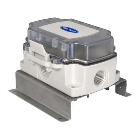
  9. Carrier 7C-SE-C68 Series User manual

Carrier 7C-SE-C68 Series User manual

For more information, contact your local Carrier Controls Expert
©2023 Carrier. All Rights Reserved. Cat. No. 11-808-989-01
INTRODUCTION
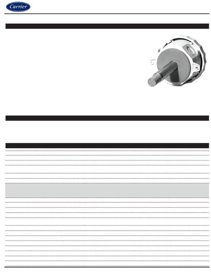
Differential Pressure Sensor (DPS) extends the sensor capabilities of ClimaVision controllers. Its
use opens an array of additional applications from flow sensing in variable air volume (VAV)
boxes to monitoring filter performance in air handling units (AHU). The compact profile and
rugged construction of DPS allow it to be mounted on the sides of VAV boxes, hard
supports, or rafters.
PACKAGE CONTENTS
•Differential Pressure Sensor
•Mounting accessories
•Sensor bus communication cable
•Pipes for static and total air flows
SPECIFICATIONS
Power
Sensor Bus powered at 3.3V with
maximum current limit of 10mA
Operating range
Temperature 30°F (0°C) to 122°F (50°C)
Pressure sensing range
0 - 2" WC or 500 Pa
Protection
Protection: IP 20, NEMA Type 1
Pollution grade: 2
Certification: ROHS
Communication
Sensor bus for daisy chained sensor
communication and low power 3V DC.
Zero-point Accuracy
0.1 Pa
Accuracy
3% of measured value
Span shift due to temperature variation
< 0.5% of reading per 10°C
Offset stability
< 0.05 Pa/year
Mounting
Firmly on the VAV box, hard supports, or
rafters. Torque not exceeding 0.2Nm to
be used to fix the device.
Flow step response time
< 3ms
Pressure medium
Air non-condensing
Storage temperature
-10°C to 70 °C
Differential Pressure Sensor
(7C-SE-C68X-X)
INSTALLATION GUIDE
Scan this QR
code to get a
more detailed
version of the
Installation
Guide
For more information, contact your local Carrier Controls Expert
©2023 Carrier. All Rights Reserved. Cat. No. 11-808-989-01
_ag‘ f[‘ X
1. Mount the Differential Pressure Sensor
using two #8-1.5” self-tapping screws as shown in
Figure 1. The transmitter is factory-calibrated and must be installed vertically with the air
inlet nozzles pointing perpendicular to the duct. To adjust the zero, both pressure ports
must be open to the atmosphere.
Figure 1
2. Mount the air pick-up pipe to the air inlet nozzles provided on the DPS. To fix the pipe,
push one end of the flexible pipe till the edge butts out to the back of the nozzle and the
other end to the crossflow tubes or pitot’s installed. See Figure 2.
Figure 2
i [d[‘ X
1. Turn off the power. Connect one end of the Sensor bus cable to one end of the RTS port
on the Smart Node and the other end to the IN port of the DPS as shown in Figure 3.
PRECAUTIONS
•Failure to wire devices with the correct polarity when using a shared transformer may
result in damage to any device powered by the shared transformer.
•Do NOT mount the tubing so that the inside or the outside tube ends are in direct line
of a breeze or draft.
•Turn off the power before wiring. Never connect or disconnect the wiring with the
power turned on. Do NOT allow live wires to touch the circuit boards.
•Install in accordance with all state and local codes.
For more information, contact your local Carrier Controls Expert
©2023 Carrier. All Rights Reserved. Cat. No. 11-808-989-01
Smart Node
Differential
Pressure Sensor
Wall Sensor
(Optional)
Sensor Bus Sensor Bus
IN
OUT
Set the switch to Yes
Left profile view
Figure 3
2. Power to the DPS is provided through the Sensor bus cable; no external power wiring is
required. If an additional Wall sensor needs to be connected, connect the other Sensor
bus cable to one end of the OUT port of the DPS and the other end to the RTH sensor.
See Figure 4 for connections.
3. To enable Wall sensor communication, the
Daisy Chain
switch must be set to
Yes
. When
there is no requirement for additional sensors to be connected to the OUT port of the
DPS, the
Daisy Chain
switch must be set to
No
. See Figure 4.
Smart Node
Differential
Pressure Sensor
Wall Sensor
(Optional)
Sensor Bus Sensor Bus
IN
OUT
Set the switch to No
Left profile view
Figure 4
On the DPS, connect the static tube to “- “and the total pressure pipe to “+”. This helps the sensor
calculate the differential pressure in the duct.
For more information, contact your local Carrier Controls Expert
©2023 Carrier. All Rights Reserved. Cat. No. 11-808-989-01
CARRIER CLIMAVISION TECHNICAL SUPPORT
Installation and servicing of Control Systems can be hazardous due to electrical components.
Only trained and qualified service personnel should install, repair or service control system
components.
For more information on wiring, commissioning, or usage of the ClimaVision product line, please
refer to any documentation provided with the job. If no documentation was provided with the job,
please use the ClimaVision Help Center (support.climavision.com) where you can find application
specific wiring schematics and helpful user guides and videos or scan the QR code here:
If you need help beyond that, please reach out to your local Carrier distributor for support.
technical support.
Scan this QR code to
get a more detailed
version of the
Installation Guide

Other Carrier Security Sensor manuals

Carrier Graviner Mk6 User manual

Carrier

Carrier Graviner Mk6 User manual

Carrier SPS User manual

Carrier

Carrier SPS User manual

Carrier Graviner Mk7 Configuration guide

Carrier

Carrier Graviner Mk7 Configuration guide

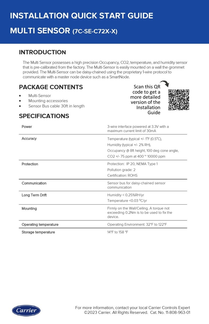
Carrier 7C-SE-C72X-X Datasheet

Carrier

Carrier 7C-SE-C72X-X Datasheet

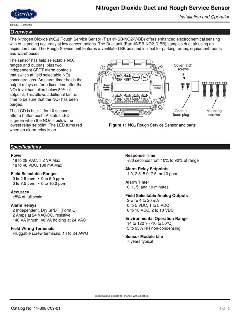
Carrier NSB-NO2-V-BB User manual

Carrier

Carrier NSB-NO2-V-BB User manual

Carrier Graviner Mk6 Configuration guide

Carrier

Carrier Graviner Mk6 Configuration guide

Carrier ARITECH VE1012PI Assembly instructions

Carrier

Carrier ARITECH VE1012PI Assembly instructions

Carrier KIDDE 60WLDR-W User manual

Carrier

Carrier KIDDE 60WLDR-W User manual

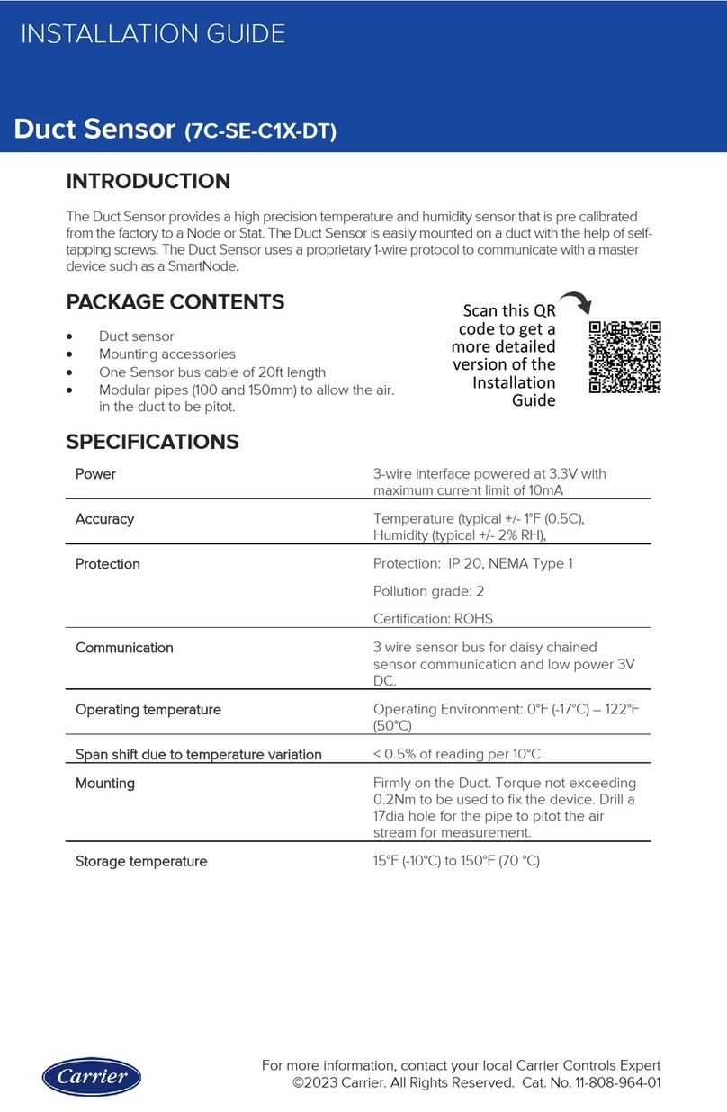
Carrier 7C-SE-C1X-DT User manual

Carrier

Carrier 7C-SE-C1X-DT User manual

Carrier Aritech 6933AMP Assembly instructions

Carrier

Carrier Aritech 6933AMP Assembly instructions

Carrier BN Series User manual

Carrier

Carrier BN Series User manual

Carrier NSB-LDT4-PS-BB Guide

Carrier

Carrier NSB-LDT4-PS-BB Guide

Carrier DET-TRONICS Dual Spectrum PM-5MPX User manual

Carrier

Carrier DET-TRONICS Dual Spectrum PM-5MPX User manual

Carrier Graviner Mk7 User manual

Carrier

Carrier Graviner Mk7 User manual
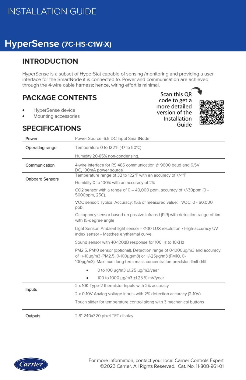
Carrier HyperSense 7C-HS-C1W-X User manual

Carrier

Carrier HyperSense 7C-HS-C1W-X User manual

Popular Security Sensor manuals by other brands

DMP 1127C PIR installation guide

DMP

DMP 1127C PIR installation guide

ecoey FJ122-H14 user manual

ecoey

ecoey FJ122-H14 user manual

LCN 8310-804 user guide

LCN

LCN 8310-804 user guide

Airthings Wave operating manual

Airthings

Airthings Wave operating manual

Ezviz T6 quick start guide

Ezviz

Ezviz T6 quick start guide

SICK GTE6V operating instructions

SICK

SICK GTE6V operating instructions

olympia electronics TC100N Operation manual

olympia electronics

olympia electronics TC100N Operation manual

Becker SC911 PLUS Assembly and operating instructions

Becker

Becker SC911 PLUS Assembly and operating instructions

PCB Piezotronics 117B25 Installation and operating manual

PCB Piezotronics

PCB Piezotronics 117B25 Installation and operating manual

Fisher Research Labs XLT-100 operating manual

Fisher Research Labs

Fisher Research Labs XLT-100 operating manual

Honeywell Notifier FSP-951AUS Installation and maintenance instructions

Honeywell

Honeywell Notifier FSP-951AUS Installation and maintenance instructions

Robertshaw 365A instruction manual

Robertshaw

Robertshaw 365A instruction manual

schmersal SFB-PN-IRT-8M12-IOP operating instructions

schmersal

schmersal SFB-PN-IRT-8M12-IOP operating instructions

Thorn SwitchLite SLDM 96019208 manual

Thorn

Thorn SwitchLite SLDM 96019208 manual

Inficon Sensistor ISH2000 HySpeed operating instructions

Inficon

Inficon Sensistor ISH2000 HySpeed operating instructions

Honeywell C554A installation instructions

Honeywell

Honeywell C554A installation instructions

Nohken VQ32 instruction manual

Nohken

Nohken VQ32 instruction manual

LEGRAND CP Electronics EBDSPIR-L3 installation guide

LEGRAND

LEGRAND CP Electronics EBDSPIR-L3 installation guide

manuals.online logo
manuals.online logoBrands
  • About & Mission
  • Contact us
  • Privacy Policy
  • Terms and Conditions

Copyright 2025 Manuals.Online. All Rights Reserved.