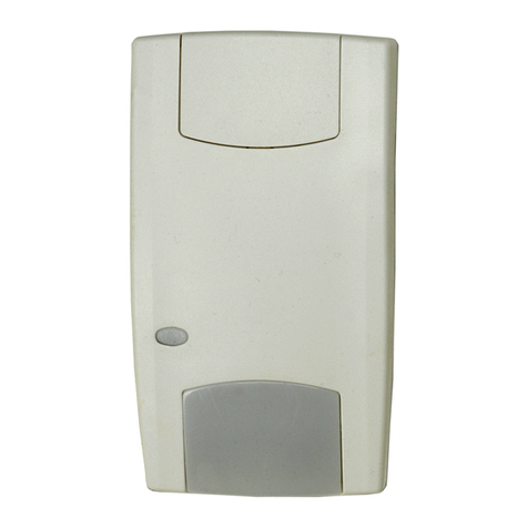
Carrier DET-TRONICS Dual Spectrum PM-5MPX User manual

Instructions
Dual Spectrum
Infrared Flame Detector
PM-5MPX
4.2 Rev: 8/13 95-8562

Table of Contents
APPLICATION ..............................2
DETECTOR USE IN HAZARDOUS AREAS .......2
ELECTRICAL CHARACTERISTICS..............2
ENVIRONMENTAL CHARACTERISTICS .........3
DETECTOR PERFORMANCE..................3
Detection Range and Response Time.........3
False Alarm Immunity .....................4
DETECTOR INSTALLATION ...................4
Physical Mounting ........................4
Electrical Wiring Connection ................4
Intrinsically Safe Circuits ...................5
Non-Incendive Circuits.....................5
System Test .............................5
Optional Test Method......................6
TROUBLESHOOTING ........................6
MAINTENANCE .............................6
Routine Visual Inspection ..................6
Periodic System Test ......................6
DEVICE REPAIR AND RETURN ................7
ORDERING INFORMATION ...................7
APPENDIX A – FM APPROVAL AND
PERFORMANCE REPORT ....................8
APPENDIX B – CONTROL DRAWING
CONFIGURATION ..........................10
APPENDIX C – INTRINSICALLY SAFE CLASS B,
STYLE B WIRING ..........................11
APPENDIX D – NON-INCENDIVE CLASS B,
STYLE B WIRING ..........................12
APPENDIX E – NON-INCENDIVE CLASS A,
STYLE D WIRING ..........................13
APPENDIX F – PSS-MP TEST LAMP ...........14

IMPORTA NT
Be sure to read and understand the entire
instruction manual before installing or operating
the Model PM-5MPX Detector. Only qualied
personnel should install, maintain or operate the
ame detection system.
CAUTION
If this equipment is used in a manner not specied
in this manual, safety protection may be impaired.
CAUTION
The wiring procedures in this manual are intended
to ensure proper functioning of the device under
normal conditions. However, because of the many
variations in wiring codes and regulations, total
compliance to these ordinances cannot be
guaranteed. Be certain that all wiring complies
with the NEC as well as all local ordinances. If in
doubt, consult the authority having jurisdiction
before wiring the system.
The Dual Spectrum®PM-5MPX is a FM Approved
infrared flame detector that provides reliable flame
detection in semiconductor fabrication facilities and other
manufacturing environments. It provides fast protection
against fires, has a maximum 110° field-of-view, and is
approved for use in hazardous (classified) locations as
described below. The detector response to explosive
fires is as fast as 25 milliseconds.
The PM-5MPX (P/N 421132) is encapsulated and
enclosed in an extremely compact molded polypropylene
housing approximately 3.1 x 3.1 x 1.7 inches in size. (See
Figure 1.) They are intended for mounting in locations
where space is at a premium. The IP67 polypropylene
housing is resistant to attack by a broad range of
chemicals. The housing has four holes in the mounting
flange that allow it to be attached to a bracket or other flat
surface. Electrical connections are made via an integral
multiconductor cable.
PM-5MPX is CE compliant only when installed in large-
scale fixed installations or large-scale stationary industrial
tools. Examples of acceptable uses include large-sclale
production and processing lines, machines for industrial
production and processing of materials and goods,
machines for testing of work pieces, paint booths, etc.
FM Approved for:
1)
performance of the flame detector per FM 3260: 2000,
2) compliance with National Fire Protection Association
(NFPA) Standard 72 of the detectors and the
installation described in this document,
3) the suitability for use in protected semiconductor
fabrication areas, as described in the FM Loss
Prevention Data Sheets 7-7/17-12, and
4) the suitability of the installation for use in hazardous
(classified) locations.
NOTE
These detectors are specically tuned and tested
to respond to res as described in this manual. The
detector response to other fuel sources not
described in this manual may vary. Please contact
Detector Electronics Corporation for further
information.
4.2 ©2020Detector Electronics Corporation Rev: 8/13 95-8562
INSTRUCTIONS
Dual Spectrum
®
Infrared Flame Detector
PM-5MPX
FM
APPROVED
®

295-85624.2
APPLICATIONS
The PM-5MPX is intended for fast detection of
hydrocarbon fueled fires in harsh chemical environments.
The detector is ideal for semiconductor wet benches and
is suitable for clean-rooms, gas cabinets, and other
indoor applications.
DETECTOR USE IN HAZARDOUS AREAS
The PM-5MPX is FM Approved to FM 3260: 2000,
intrinsically safe for use in Class I, II, III, Division 1,
Groups C, D, E, F & G hazardous (classified) locations;
non-incendive for use in Class I, Division 2 Groups A, B,
C & D locations and suitable for use in Class II/III Division
2, Groups F & G. This Approval depends on proper
installation and choice of components, which are
described in this installation manual. See the following
sections and Control Drawing Configuration (Appendix B)
for installation instructions and component selection
criteria.
ELECTRICAL CHARACTERISTICS
The PM-5MPX is designed to interface to any NFPA type
fire alarm control panel. A normally open solid-state relay
is provided for an alarm signal. The relay closes for a
minimum of five and a maximum of 15 seconds when a
fire is detected and is automatically reset after a fire. An
internal supervision solid-state relay closes when the
detector powers up and opens if a detector fault (such as
loss of power or low power supply voltage) occurs. In
NFPA 72, Class A or B circuits (see Appendix C, D and
E), such a fault condition is indicated at the control panel
as a trouble signal. A blinking red LED on the front of the
housing indicates the following:
1 Hz rate = Normal operation
3-4 Hz rate = Alarm condition.
OPERATING VOLTAGE—
9 to 30 Vdc at the detector (observe polarity), including
line drops and ripple.
NOTE
Detector output is not guaranteed below 9 Vdc.
The status LED and relay will reect this condition.
POWER CONSUMPTION—
10 milliamps maximum at +30 Vdc.
ALARM OUTPUT—
Solid-state alarm relay is non-latching. Contacts close for
5 to 15 seconds.
TROUBLE OUTPUT—
Opening of normally closed solid-state relay.
SOLID -STATE RELAY RATINGS —
100 mA at 30 Vdc; 30 ohms.
STABILIZATION TIME—
Maximum 0.5 second after power up.
RESPONSE TIME—
1 second maximum.
WIRING HARNESS—
Identification: See Table 1.
Length: 50 feet (15.24 m).
Diameter: 0.3 inches (7.62 mm).
Individual Wires: 20 AWG, stranded.
2.5
3.1
1.7
3.1 2.5
4 x 0.203
Figure 1—Dimensions of PM-5MPX in Inches

395-85624.2
ENVIRONMENTAL CHARACTERISTICS
TEMPERATURE RANGE—
Operating: 0°C to +49°C (+32°F to +120°F ).
Storage: 0°C to +70°C (+32°F to +158°F).
RELATIVE HUMIDITY—
0 to 93% relative humidity.
NOTE
Water or other liquids on the face of the detector
may decrease sensitivity.
ENCLOSURE RATING—
I P 67.
VIBRATION—
Compliance with FM Approval Standard FM 3260: 2000.
ELECTROMAGNETIC INTERFERENCE—
Highly resistant to radiated and conducted Electromagnetic
Interference (EMI). The detectors are immune to radiated
fields of 100 volts per meter, including amplitude and
frequency modulated (AM & FM) signals in the frequency
range of 1 MHz to 1 GHz. The detectors can operate in the
presence of conducted noise levels up to 1.0 VRMS in the
frequency range of 30 Hz to 250 kHz while the input
voltage, including noise, remains between 9 and 30 volts.
CERTIFICATION—
FM: Refer to Appendix A for details.
CE: See Special Conditions for Safe Use.
Special Conditions for Safe Use:
• The PM-5MPX Detector may only be installed,
connected or removed when the area is known to be
non-hazardous.
• The PM-5MPX Detector may only be used in indoor
applications that are independent of building fire
protection systems.
• The PM-5MPX plastic cover is liable to be damaged by
impact. The unit should be installed in such a manner
as to protect the cover from mechanical damage.
DETECTOR PERFORMANCE
DETECTION RANGE AND RESPONSE TIME
Best performance is achieved when the detector is
mounted so that the protected area is within the range, or
detection threshold distance (refer to Appendix A for test
result data), and within the 110° field of view (see Figure
2). The PM-5MPX detector can respond to fires in as little
as 25 milliseconds. Actual detection time depends on the
distance between the detector and the fire, the source of
fuel, ignition sources and other aspects of the initial fire
stages. The detector has a typical response time of <0.5
second to the fires specified in Appendix A. The detector
can respond most quickly to closer or larger fires, but is
unlikely to detect fires occurring further than the indicated
distance. The range is reduced when the fire occurs
close to the edge of the field of view of the detector. At
the edge (±55° off axis) the range is reduced no more
than 50%.
NOTE
The detector range to res not listed in Appendix A
will vary and should be veried by re tests using
the fuel in question. Please contact Detector
Electronics Corporation for further information.
Table 1—PM-5MPX Wiring Harness Identication
0
15
30
45
15
30
45
55
55
100%
A2004
0
15
30
45
15
30
45
55
55
8 ft
4 ft
2 ft
6 ft
10 ft
A2004
57.5 57.5
50%
90%
80%
70%
60%
40%
30%
20%
10%
Figure 2—Graphical Representation of Detector Range as a
Function of Angle from the Optical Axis
Wire Color Description
Black Power Return
Brown Power Return
Red V+, Input Power
Orange V+, Input Power
Yellow Alarm +
Green Alarm +
Blue Alarm –
Violet Alarm –
Gray Trouble +
White Trouble –

495-85624.2
FALSE ALARM IMMUNITY
The PM-5MPX is highly resistant to false alarms. However,
a fire alarm output due to non-fire stimuli is possible.
(Refer to Appendix A for a list of common stimuli and the
false alarm immunity distance for those stimuli, as tested
by FM Approvals. No false alarms occur for larger
distances in laboratory measurements.)
The detector is intended for use in indoor locations. For
best performance, the detector should be mounted so
that any exposure to false alarm sources occurs only at
distances greater than the indicated distances. In
addition, to ensure optimum performance, detectors
should be mounted so that they do not view very brightly
illuminated areas. For example, indoor mounting locations
where the detectors look out doors or windows should be
avoided.
DETECTOR INSTALLATION
PHYSICAL MOUNTING
The PM-5MPX must be installed in conformance with the
appropriate drawing provided in this manual, NFPA-72,
the NEC, and all local codes for the hazard classification
of the location to be protected. The detector comes with
an integral multi-conductor cable for the alarm and
power circuits.
CAUTION
The factory sealed front cover is essential to the
approval of the detectors. Removing this cover will
compromise the performance of the detector.
The compact package of the PM-5MPX is of great benefit
in applications where space is a limiting factor. It has four
holes in the mounting flange that can be used to mount
the detector directly to a flat surface or bracket. Take care
not to over-tighten mounting hardware.
The number of detectors required to protect a given area
will depend on the size of the area, the distance from the
detector and the size and type of the fire threat. Certain
factors need to be considered when designing an
installation:
1. The detectors should be installed so that objects do
not block their field of view. This includes glass,
plexiglass, and other visibly transparent materials.
2. Whenever possible, detectors should be installed so
their ranges and fields of view overlap.
3. Detectors should be installed so they will not be
blocked by moving machinery or personnel during
normal operations within the area.
4. To ensure optimum sensitivity and performance,
detectors should be installed so they do not view
brightly illuminated areas.
5. The detectors should be installed so that they are
easily and safely accessible for inspection and
maintenance.
6. If mechanical or high-temperature damage, or
window contamination is likely in the installed location,
then the detectors should be protected. However, the
protection method cannot obstruct the detector’s
field of view with any material, including visibly
transparent materials like glass and plexiglass.
7. The detector should be installed in a position higher
than the hazard.
8. Installation of detectors in a location prone to
submersion must be avoided. Submerged detectors
will not detect fire.
9. Detectors should be installed in locations that do not
exceed the operating temperature range (including
ambient temperature and exposure to liquids).
ELECTRICAL WIRING CONNECTION
An approved installation of the PM-5MPX flame detector
must be in accordance with the FM Approved drawings
included as appendices to this manual and all local
codes. The required drawing for specific hazardous
(classified) or non-hazardous locations can be determined
from the Control Drawing Configuration (Drawing 420031,
Appendix B). Detectors may be wired in a standard NFPA
class B, style B configuration or in a class A, style D
configuration. Approved initiating device circuits may be
either intrinsically safe, non-incendive, or suitable for the
classified location as required.
595-85624.2
INTRINSICALLY SAFE CIRCUITS
Intrinsically safe installations require the use of suitable
and approved barriers, an approved fire alarm control
panel that is compatible with the barriers, and wiring
methods consistent with ANSI/ISA-RP12.6 and other
code. Appendix C calls out the type and quantity of
barriers required for installation in hazardous (classified)
locations and shows the electrical interconnection to an
NFPA compliant fire alarm control panel. Wiring that
passes from the non-hazardous location to the hazardous
location should pass through a seal appropriate for the
type of hazard. All control room instrumentation must
operate at less than 250 VRMS.
The barriers may be located in the main control panel or
in a separate enclosure, but adequate separation between
intrinsically safe and non-intrinsically safe wiring must be
observed as defined by ANSI/ISA-RP12.6. Barrier
grounds should be connected separately to the same
grounding location.
All initiating device wiring should be run in its own
separate raceway. Table 2 gives the maximum one way
wiring distances based on wire and barrier resistance. It
is also important not to exceed the maximum inductance
and capacitance listed on the intrinsic safety barriers.
This may restrict the maximum cable length to less than
the values listed in Table 2. Consult Appendix C for
further instructions.
AWG
(Solid)
Maximum One Way
Wiring Distance in Feet
(Excluding Integral Cable)
14-18
20
22
1000
600
400
NON-INCENDIVE CIRCUITS
In Class I, Division 2, Group A, B, C, & D locations, the
detector may be installed in non-incendive circuits. It is
also suitable for installation in Class II/III, Division 2,
Group F & G hazardous locations. Installations require
the use of an approved fire alarm control panel that is
compatible with the Class B, Style B and/or Class A,
Style D initiating device circuits. See Appendix D and E.
NOTE
ANSI/NFPA 70 (NEC) Article 501-4(b) requires the
use of enclosed gasketed wireways.
SYSTEM TEST
After the fire protection system is installed, it should be
tested for correct operation. The detectors may be tested
with live fires or by using the hand-held model PSS-MP
Test Set P/N 420116. The details of this sequence will
vary with particular installations, but the procedure must
include the following steps. See Appendix F.
PSS-MP Test Procedure
WARNING
A full system test results in an alarm output. This
will result in the automatic suppression system
being activated if it is not disabled prior to testing.
1. Suppression System. Disable the suppression
system if its activation is not desired during this test.
WARNING
Do not use the PSS-MP Test Lamp unless the area
is known to be non-hazardous.
2. Fire Response Test. Turn on the PSS-MP and wait
at least 15 seconds. Direct the beam into the front of
the detector to cause an alarm output. Hold the
PSS-MP so that the infrared filter is less than 1 inch
from the front of the flame detector to be tested as
shown in Figure 3. The control panel should indicate
an alarm condition at the detector under test. See
Appendix F for additional information.
Table 2—Maximum Wiring Distances
Figure 3—Testing a PM-5MPX with the PSS-MP Test Lamp

695-85624.2
3. Interconnection Wiring. Correct interconnection
wiring should be checked by disconnecting any wire
from the multi-conductor cable were it is connected
to the power or alarm circuit. The result, in an
approved wiring scheme, should be a trouble signal
indication at the control panel.
4. Restore Fire Protection System. Restore the
system to an operational condition after all tests have
been completed.
OPTIONAL TEST METHOD
With the detector powered up, the following tests can be
done. False alarm immunity can be checked using stimuli
and distances shown in the table in Appendix A. Fire
response can be checked by exposing the detector
under test to a live fire source. (See Appendix A.) Follow
all required precautions when testing in this manner.
TROUBLESHOOTING
See Table 3.
MAINTENANCE
ROUTINE VISUAL INSPECTION
A properly installed PM-5MPX detector system is highly
resistant to blinding by contamination build-up on the
detector front face window. However, a thick enough
build-up will begin to reduce the performance of the
detector. This can be prevented by periodically inspecting
installed detectors visually for contamination build-up on
the detector front face. If such a build-up is observed, it
should be removed by cleaning the detector front face
window with a soft cloth or lens tissue. The minimum
inspection period should be compatible with appropriate
regulating agency requirements.
WARNING
To prevent the risk of electrostatic discharge, the
surface of the detector should only be cleaned with
a damp cloth.
PERIODIC SYSTEM TEST
The authority having jurisdiction and internal facility
requirements generally call for routine testing of safety
systems at defined intervals, which, at a minimum, should
conform to the requirements of NFPA 72. These tests
should include visual inspections and the steps listed in
the System Test section above.
Table 3—Troubleshooting Guide
Symptom Probable Cause Corrective Action
Trouble signal at fire alarm control panel.
Incorrect wiring Check circuit installation.
Low or no voltage to detector.
Check voltage of Red or Orange wire with
respect to the Black or Brown wire. Should be
9 to 30 Vdc.
Detector malfunction. Replace detector
Detector does not alarm during FIRE
RESPONSE test with PSS-MP.
Incorrect wiring. Check circuit installation.
PSS-MP temperature different from detector.
Allow detector and PSS-MP temperatures to
stabilize. Turn on PSS-MP at least 15 seconds
prior to test.
Low batteries in PSS-MP. Replace batteries and retest.
Detector malfunction. Replace detector.
Red LED out.
Incorrect wiring or incorrect power to the
detector. Check circuit installation.
Detector malfunction. Replace detector.

795-85624.2
WARNING
A full system test results in an alarm output. This
will result in the suppression system being activated
if it is not disabled prior to testing.
DEVICE REPAIR AND RETURN
The PM-5MPX is completely potted, which does not
allow it to be repaired. If a problem should develop,
carefully check system wiring and ensure that power is
applied to the device. If it is determined that the problem
is caused by a detector failure, the PM-5MPX must be
replaced.
ORDERING INFORMATION
When ordering, please specify:
PM-5MPX Dual Spectrum®Infrared Flame Detector
For assistance in ordering a system to meet the needs of
a specific application, contact:
Detector Electronics Corporation
6901 West 110th Street
Minneapolis, Minnesota 55438 USA
Operator: (952) 941-5665 or (800) 765-FIRE
Customer Service: (952) 946-6491
Fax: (952) 829-8750
Web site: www.det-tronics.com
E-mail: det-tronics@det-tronics.com

895-85624.2
APPENDIX A
FM APPROVAL DESCRIPTION AND PERFORMANCE REPORT
HAZARDOUS LOCATION RATINGS
• Intrinsically safe for Class I, II, III, Div. 1, Groups C, D, E, F and G Hazardous (Classified) Locations per FM 3610.
• Non-incendive for Class I, Div. 2, Groups A, B, C and D Hazardous (Classified) Locations per FM 3611.
AUTOMATIC FIRE ALARM SIGNALING PERFORMANCE (FM 3620: 2000)
RESPONSE CHARACTERISTICS
(Typical Response Time < 0.5 Sec.)
Fuel Size Distance
(feet)
n-Heptane 1 x 1 foot 18
Isopropanol 8 in. dia. 8
Polypropylene 8 in. dia. 8
NOTE: Response time measurements based upon
shuttered test method.
FALSE ALARM IMMUNITY
False Alarm Source Distance
(inches) Modulated Response Unmodulated
Response
Arc welding, Type E6012 rod, 1/8” dia., 1/4” plate 42 No alarm No alarm
70 W sodium vapor lamp 6No alarm No alarm
250 W mercury vapor lamp 12 No alarm No alarm
300 W incandescent lamp 8No alarm No alarm
500 W quartz halogen lamp shielded w/window 30 No alarm No alarm
1500 W electric quartz heater 108 No alarm No alarm
Two 34 W fluorescent lamps <3 No alarm No alarm

995-85624.2
FM Approval Description and Performance Report – Continued
FALSE ALARM IMMUNITY COMBINED WITH FIRE SOURCE
False Alarm Source
False Alarm
Source Distance
(feet)
Fire Source
Fire Source
Distance
(inches)
Arc welding, unmodulated 3.5 10 in propane 12
Arc welding, modulated 3.5 10 in propane 12
70 W sodium vapor lamp, unmodulated 0.5 10 in propane 24
70 W sodium vapor lamp, modulated 0.5 10 in propane 19
250 W mercury vapor lamp, unmodulated 1.0 10 in propane 20
250 W mercury vapor lamp, modulated 1.0 10 in propane 20
300 W incandescent lamp, unmodulated 0.67 10 in propane 27
300 W incandescent lamp, modulated 0.67 10 in propane 21
500 W shielded quartz halogen lamp, unmodulated 2.5 10 in propane 25
500 W shielded quartz halogen lamp, modulated 2.5 10 in propane 18
1500 W electric quartz heater, unmodulated 910 in propane 24
1500 W electric quartz heater, modulated 910 in propane 27
Two 34 W fluorescent lamps, unmodulated 0.25 10 in propane 20
Two 34 W fluorescent lamps, modulated 0.25 10 in propane 24
FIELD OF VIEW
(Typical Response Time <0.5 Sec.)
Fuel Size Distance
(feet)
Vert./Horiz.
(degrees)
n-Heptane 1 x 1 foot 9+55
–55
Isopropanol 8 in. dia. 4+55
–55
Polypropylene 8 in. dia. 4+55
–55
NOTE: Response time measurements based upon
shuttered test method.

10 95-85624.2
APPENDIX B
CONTROL DRAWING CONFIGURATION
Figure B1—Control Drawing Conguration (Drawing No. 420031)
PM-5MPX CONTROL DRAWING CONFIGURATION
HAZARDOUS (CLASSIFIED) NFPA 72 INITIATING INSTALLATION TYPE CONTROL
LOCATION DEVICE CIRCUIT DWG NO.
CLASS & STYLE
CLASS I, DIV. 1, GROUPS C & D CLASS B, STYLE B INTRINSICALLY SAFE 420032
CLASS II, DIV. 1, GROUPS E, F & G CLASS B, STYLE B INTRINSICALLY SAFE 420032
CLASS I, DIV. 2, GROUPS A, B, C & D CLASS B, STYLE B INTRINSICALLY SAFE 420032
CLASS II, DIV. 2, GROUPS F & G CLASS B, STYLE B INTRINSICALLY SAFE 420032
CLASS III, DIV. 2 CLASS B, STYLE B INTRINSICALLY SAFE 420032
CLASS I, DIV. 2, GROUPS A, B, C & D CLASS B, STYLE B NON-INCENDIVE 420033
CLASS II, DIV. 2, GROUPS F & G CLASS B, STYLE B NON-INCENDIVE 420033
CLASS III, DIV. 2 CLASS B, STYLE B NON-INCENDIVE 420033
NON-HAZARDOUS (UNCLASSIFIED) CLASS B, STYLE B NON-INCENDIVE 420033
CLASS I, DIV. 2, GROUPS A, B, C & D CLASS A, STYLE D NON-INCENDIVE 420034
CLASS II, DIV. 2, GROUPS F & G CLASS A, STYLE D NON-INCENDIVE 420034
CLASS III, DIV. 2 CLASS A, STYLE D NON-INCENDIVE 420034
NON-HAZARDOUS (UNCLASSIFIED) CLASS A, STYLE D NON-INCENDIVE 420034

11 95-85624.2
APPENDIX C
INTRINSICALLY SAFE
CLASS B, STYLE B WIRING
Hazardous (Classied) Locations:
Class I, Division 1, Group C, D
Class I, Division 2, Group A, B, C, D
Class II, Division 1, Group E, F, G
Class II, Division 2, Group F, G
Class III, Division 2
NOTES: 1. SUITABLE FOR INTRINSICALLYSAFE
INSTALLATION IN CLASS I, DIV. 1, GP. C,
D; CLASS I, DIV. 2, GP. A, B, C, D; CLASS
II, DIV . 1, GP. E, F & G; CLASS II, DIV. 2,
GP. F & G. CLASS III, DIV. 2 HAZ-
ARDOUS LOCATIONS. WIRING METH-
ODS SHALL BE INSTALLED IN ACCOR
DANCE WITH ANSI/NFPA70 (NEC),
ANSI/NFPA72 AND ISA RP12.6.
2. I. S. BARRIERS MUST BE INSTALLED IN
ACCORDANCE WITH THE
MANUFACTURER’S GUIDELINES.
3. THIS DRAWING SHOWS ONE SENSOR
CONNECTED IN ACLASS B, STYLE B
CONFIGURATION PER NFPA72.
MULTIPLE SENSORS MAYNOT BE
CONNECTED TO THE SAME BARRIER.
AN END OF LINE DEVICE (EOL) IS
REQUIRED TO MONITOR LINE
CONTINUITY.
4. END OF LINE DEVICE VALUE PLUS
BARRIER RESISTANCE MUST PROVIDE
ADEQUATE SUPERVISION CURRENT
FOR FIRE ALARM CONTROL PANEL.
5. RESISTANCE BETWEEN BARRIER
GROUND AND EARTH GROUND MUST
NOT EXCEED ONE OHM.
6. PM-5MPX INTERCONNECTS VIA FLYING
LEAD. EXTENSION CABLE SHALL
COMPLYWITH ANSI/NFPA70 (NEC)
ARTICLE 504-30(b)(2).
7. CABLE SHIELD MUST BE TIED TO
INTRINSIC SAFETY GROUND AT THE
BARRIER.
8. THE PM-5MPX SENSOR HAS BEEN
SYSTEM APPROVED WITH THE FM
APPROVED BARRIERS LISTED IN THE
BARRIER TABLE.
9.MAXIMUM CABLE LENGTH: 1000 FEET.
PM-5MPX
ELECTRICAL INTERFACE
Wire Color Signal
Red V+, Input Power
Orange V+, Input Power
Black Power Return
Brown Power Return
Yellow Alarm +
Green Alarm +
Blue Alarm –
Violet Alarm –
Gray Trouble +
White Trouble –
BARRIER PARAMETERS
MODEL MANUFACTURER Vt (V) It (MA)
9002/77-280-094-00 STAHL 28.1 87.0
Z978 PEPPERL + FUCHS 30.0 93.0
7278ac MTL 28.0 94.0
BARRIER TABLE
Figure C1—Intrinsically Safe Class B, Style B Wiring (Drawing No. 420032)

12 95-85624.2
APPENDIX D
NONINCENDIVE
CLASS B, STYLE B WIRING
Hazardous (Classied) Locations:
Class I, Division 2, Group A, B, C, D
Class II, Division 2, Group F, G
Class III, Division 2
Non-hazardous (Non-classied) Locations
Figure D1—Non-Incendive Class B, Style B Wiring (Drawing No. 420033)
PM-5MPX
ELECTRICAL INTERFACE
Wire Color Signal
Red V+, Input Power
Orange V+, Input Power
Black Power Return
Brown Power Return
Yellow Alarm +
Green Alarm +
Blue Alarm –
Violet Alarm –
Gray Trouble +
White Trouble –
NOTES: 1. FOR INSTALLATION IN NONINCENDIVE,
CLASS I, DIVISION 2, GROUPS A, B, C &
D; CLASS II, DIVISION 2, GROUPS F & G;
CLASS III, DIVISION 2 HAZARDOUS
(CLASSIFIED) LOCATIONS, OR NON-
HAZARDOUS LOCATIONS ONLY. WIRING
METHODS SHALL BE INSTALLED IN
ACCORDANCE WITH ANSI/NFPA
70 (NEC) ARTICLE 501-4(b) AND
ANSI/NFPA72.
2. THIS DRAWING SHOWS THREE
SENSORS CONNECTED IN ONE ZONE
IN A CLASS B, STYLE B
CONFIGURATION PER NFPA72.
ADDITIONAL SENSORS CAN BE ADDED
BY REPEATING THE WIRING PATTERN
OF THE CENTRAL SENSOR.
3. PM-5MPX INTERCONNECTS VIA FLYING
LEAD.
4. ELECTRICAL REQUIREMENT: 9 TO 30
VDC AND 10 MILLIAMPS (MAX) PER
SENSOR.
5. AN END OF LINE DEVICE, AS
REQUIRED BY THE FIRE ALARM
CONTROL PANEL, IS USED TO
MONITOR LINE CONTINUITY.

13 95-85624.2
NOTES: 1. FOR INSTALLATION IN NONINCENDIVE,
CLASS I, DIVISION 2, GROUPS A, B, C &
D; CLASS II, DIVISION 2, GROUPS F & G;
CLASS III, DIVISION 2 HAZARDOUS
(CLASSIFIED) LOCATIONS, OR NON-
HAZARDOUS LOCATIONS ONLY. WIRING
METHODS SHALL BE INSTALLED IN
ACCORDANCE WITH ANSI/NFPA
70 (NEC) ARTICLE 501-4(b) AND
ANSI/NFPA72.
2. THIS DRAWING SHOWS THREE
SENSORS CONNECTED IN ONE ZONE
IN A CLASS A, STYLE D
CONFIGURATION PER NFPA72.
ADDITIONAL SENSORS CAN BE ADDED
BY REPEATING THE WIRING PATTERN
OF THE CENTRAL SENSOR.
3. PM-5MPX INTERCONNECTS VIA FLYING
LEAD.
4. ELECTRICAL REQUIREMENT: 9 TO 30
VDC AND 10 MILLIAMPS (MAX) PER
SENSOR.
5. THE OUTGOING AND RETURN
(REDUNDANT) CIRCUIT CONDUCTORS
SHALL NOT BE RUN IN THE SAME
CABLE ASSEMBLY, ENCLOSURE, OR
RACEWAY PER NFPA72.
PM-5MPX
ELECTRICAL INTERFACE
Wire Color Signal
Red V+, Input Power
Orange V+, Input Power
Black Power Return
Brown Power Return
Yellow Alarm +
Green Alarm +
Blue Alarm –
Violet Alarm –
Gray Trouble +
White Trouble –
Figure E1—Non-Incendive Class A, Style D Wiring (Drawing No. 420034)
APPENDIX E
NON-INCENDIVE
CLASS A, STYLE D WIRING
Hazardous (Classied) Locations:
Class I, Division 2, Group A, B, C, D
Class II, Division 2, Group F, G
Class III, Division 2
Non-hazardous (Non-classied) Locations

14 95-85624.2
APPENDIX F
PSS-MP TEST LAMP
Figure F1—PSS-MP Test Lamp
LAMP REPLACEMENT
REPLACE XENON LAMP MODULE WITH PN 18801 (UNDERWATER KINETICS).
WARNING
THIS UNIT IS NOT RATED FOR USE IN HAZARDOUS (CLASSIFIED) LOCATIONS.
CAUTION
AFULL SYSTEM TEST RESULTS IN AN ALARM OUTPUT. THIS WILL RESULT IN THE
AUTOMATIC SUPPRESSION SYSTEM BEING ACTIVATED IF IT IS NOT DISABLED PRIOR
TO TESTING.
OPERATION
TURN ON PSS-MP, WAIT 15 SECONDS. TO CAUSE AN ALARM, HOLD PSS-MP SO THAT
THE INFRARED FILTER LENS IS LESS THAN 1 INCH FROM THE FRONT OF THE FLAME
DETECTOR TO BE TESTED. IT CAN TAKE SEVERAL SECONDS FOR THE DETECTOR TO
ALARM.
NOTE
FOR VALID TEST RESULTS, THE TEST LAMP AND THE SENSOR UNDER TEST MUST BE
AT APPROXIMATELYTHE SAME TEMPERATURE.
BATTERYREPLACEMENT
THE TEST LAMP REQUIRES 6 ALKALINE C-SIZE BATTERIES.
WARNING
CHANGE BATTERYIN NON-HAZARDOUS LOCATION ONLY.
ON
OFF
INFRARED BEAM
INFRARED FILTER LENS
8 5/8
2 3/8
+
+
+
+
+
+
C
CCC
CC

95-8562
X3301 Multispectrum
IR Flame Detector
FlexSonic®Acoustic
Leak Detector
PointWatch Eclipse®IR
Combustible Gas Detector
FlexVu®Universal Display
with GT3000 Toxic Gas Detector
Eagle Quantum Premier®
Safety System
Corporate Office
6901 West 110th Street
Minneapolis, MN 55438 USA
www.det-tronics.com
Phone: +1 952.941.6665
Toll-free: +1 800.765.3473
Fax: 952.829.8750
det-tronics@carrier.com
Specications subject to change without notice.
All trademarks are the property of their respective owners.
© 2020 Detector Electronics Corporation. All rights reserved.
Det-Tronics manufacturing system is certied to ISO 9001—
the world’s most recognized quality management standard.
This manual suits for next models
1
Table of contents
Other Carrier Security Sensor manuals

Carrier
Carrier 7C-SE-C68 Series User manual

Carrier
Carrier HyperSense 7C-HS-C1W-X User manual

Carrier
Carrier Graviner Mk6 Configuration guide

Carrier
Carrier Graviner Mk6 User manual

Carrier
Carrier NSB-NO2-V-BB User manual

Carrier
Carrier Graviner Mk7 User manual

Carrier
Carrier Graviner Mk7 Configuration guide

Carrier
Carrier 7C-SE-C72X-X Datasheet

Carrier
Carrier Aritech 6933AMP Assembly instructions

Carrier
Carrier 7C-SE-C1X-DT User manual