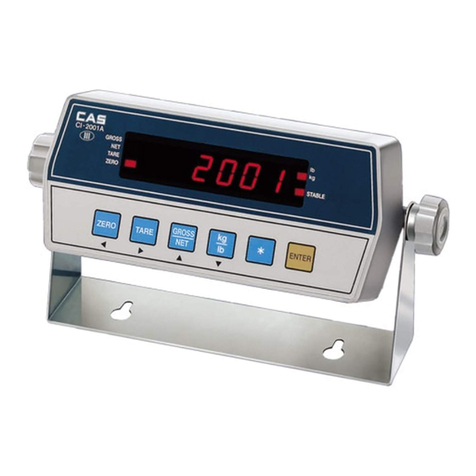
CAS CI-1500 User manual

38
CONTENTS
PRECAUTIONS............................................................. 4
INTRODUCTION........................................................... 6
FEATURES.................................................................... 6
TECHNICALSPECIFICATION....................................... 7
MEASUREOFAPPEARANCE...................................... 8
FRONTPANEL............................................................. 9
REARPANEL...............................................................10
INSTALLATION&CONNECTION.................................11
TESTMODE.................................................................13
CALIBRATIONMODE...................................................16
SETMODE...................................................................20
WEIGHINGMODE........................................................28
RS-232CINTERFACE/CLOCK......................................32
ERRORMESSAGEANDTROUBLESHOOTING..........36

54
PRECATUTIONS
nPlacetheindicatoronaflatandstable
surface.nDonotsubjectthescaletosudden
temperaturechanges.
nThisscalemustbeinstalledinadryand
liquidfree environment.nDonotseverelypress becausethelight
pressingofkeyscanincitetheoperation.
nDonotuseinflammablematerialsin
cleaning
nKeepthescaleawayfromstrongEMInoisesmaycauseincorrectweightreading

7
6
Wegreatlyappreciateyourpurchaseofthe
CI-1500
weighingindicator.Thesegoods
performexcellentlyandexhibitsplendidpropertiesthroughstriketests.CASindicator
(CI-series)isdelicatelydesignedtocoincidewiththespecialrequirementsofseveral
industrialfieldsandincludesmanyfunctionsandvariousexternalinterfaces.Also,itis
programmedfortheuser'sconvenienceandcontainshelpdisplayfunctionsthatare
easilyaccessible.
Beforeusing
CI-1500ASeries
,Itisrecommendedthatyoureadthismanualcarefullyso
youmayusethisdevicetoitsfull potential.
INTRODUCTION
CI-1500/1560AFEATURES
1.Features
n
Highquality,Highaccuracy
n
Appropriateforweightandmeasurementsystem
n
Easyoperationandvariousoptions
n
Displayof6digit(7Segment)
n
RFI/EMIscreened
n
WATCHDOGcircuitry(Systemrestoration)
n
WEIGHTBACK-UP(Memorytheweightatsuddenpowerfailure)
n
Storedate,timeandcalculateddataatsuddenpowerfailure
n
Adjustabledisplayrate(Digitalfilterfunction)
n
Tareweightsettingwithkeys
n
Userscansetmaximumweightwhichuserswanttoanddivisionatone'sdisposal
n
Selftesthardwarefunction
n
Independentzerocalibration
n
ExternalInput/Output-(CI-1560A)
:2ExternalInput-(zero,F08)
4ExternalOutput-(zero,1Step,2Step,Final)
n
Serialprinterconnection
n
Printdateandtimebyinnerclock
2.MainFunction
TECHNICALSPECIFICATION
Analog Part & A/D Conversion
Load cell Excitation Voltage DC 5V
Zero adjust range 0.05 mV~30mV
Input Sensitivity over 1 μV/D
Nonlinearity 0.01% F.S.
A/D internal resolution 1/100,000
A/D external resolution 1/10,000(Max.)
A/D conversion speed 10 times/sec
Digital Part
Span Calibration Full Digital Calibration
(Single pass automatic span calibration)
Input noise below 0.3 μVpp
Input impedance over 10 ㏁
Display 7 Segment (6 digit)
Maximum Capacity 999999
Division x 2, x 5, x 10, x 20, x 50
Display below zero "-" minus signal
Permitted limit tare Full capacity
Lamp Description
" STABLE " LAMP Weight is stable
" TARE " LAMP Tare is used
" NET " LAMP ON(NET weight), OFF(GROSS weight)
" HOLD " LAMP Hold in Weight
" ZERO " LAMP "0" kg
±
9
8
GENERAL SPECIFICATION
Power AC 220V, 50/60 Hz
Size 110(W) x 130(D) x 66(H)
Temperature -10℃~+40℃
Weight Approx 750g
Power Consumption Approx 10W
MEASUREOFAPPEARANCE
FRONTPANEL
1.WeightdisplayLamp
n
STLamp:turnonwhentheweightisstable.
n
TARELamp:turnonwhentareweightisstored.
n
NETLamp:turnonwhenthecurrentweightisNetweight.
n
HOLDLamp:turnonwhentheweightisheldwhileweighingmovingoralivethings.
n
ZEROLamp:turnonwhenthecurrentweightis0kg.
2.Keyboard
Used to return the display to the 0.
User set the zero range within 4% or 10% of the maximum capacity(F09).
Used to enter the TEST mode.
Used to weigh item by using the container.
When this key is pressed, the scale stores current weight as the tareweight.
If you press TARE key in unload condition, tare setting is released.
Used to enter the SET mode.
Used to current value X 10 in CAL, SET mode.
Use this key to switch from GROSS to NET weight.
The annunciators and display will alternate between GROSS and NET aswell.
In case tare weight is REGISTERED, tare plus item's weight is GROSS weight
and only item's weight is NET weight.
When the Lamp turning on, it means NET weight.
Used to set current value+1 in CAL, SET mode.
When you press this key, the current designated printing form is printed.
Use this key when weighing data is printed.
Used to set the when weighing data is printed.
Used to set the current value - 1 in SET mode.
Used to store current condition and exit in CALIBRATION, TEST, SET mode.
Used to enter the CAL mode.
ZERO
TARE
3
NET
GROSS
5
3
PRINT
SET

11
10
REARPANEL
n
INPUT:Externalinput
ZERO
key,
START
key(F08)
n
OUTPUT:Externaloutput(relayoutput)
ZERO,LOW,HIGH,FINAL
n
LOADCELL :Portforconnectingloadcell.
1:EX+2:EX-3:SIG+4:SIG-5:GND
n
POWER:POWERON/OFF
n
AC:Onlyfor220V50/60 Hz
n
SERIAL:RS-232C
INSTALLATION&CONNECTION
Loadcell connection
Pin1:Excitationvoltage+
Pin2:Excitationvoltage-
Pin3:Sensevoltage+
Pin4:Sensevoltage-
Pin5:Shield
n
Connectingmethod
4EachL/Cmanufacturer’sormodel’s
wirecolorcouldbedifferent.Inthat
case,pleasenotethefollowing
diagram.
n
Manufacturer’swirecolor
Connector
Company Pin 1
(EX +) Pin 3
(EX - ) Pin 5
(SIG +) Pin 6
(SIG - ) Pin 7
(SHIELD)
CAS RED WHITE GREEN BLUE CASE
KYOWA RED BLACK GREEN WHITE CASE
INTERFACE RED BLACK GREEN WHITE CASE
P.T RED BLACK GREEN WHITE CASE
BLS GREEN BLACK WHITE RED YELLOW
SHOWA RED BLUE WHITE BLACK CASE
SHINKOH RED BLACK GREEN WHITE CASE
TMI RED WHITE GREEN BLUE YELLOW
TML RED BLACK WHITE GREEN CASE
TFAC RED BLUE WHITE BLACK YELLOW
HUNTLEIGH GREEN BLACK RED WHITE CASE

13
12
n
Resolutiontoloadcell outputrate
10V impression to load cell Max.
load cell output Recommended resolution
2 mV 1/1,000(Max)
4 mV 1/2,000(Max)
8 mV 1/5,000(Max)
ConnectiontoACpower
ConnecttotheACpowerandturnthepowerswitchon.
TheInputVoltageisonlyfor220V50/60 Hz
Externalinputportconnection
IfyouareawayfromCI-1500Aandyouwanttocontrolkey,Pleaseconnectthe
CI-1500Awith
remotekey
viarearpanel.
ExternalOutputportconnection(realyis5W)
Multi Connector Relay
1ZERO RELAY
REALY OUT-PUT
21 STEP(LOW RELAY)
32 STEP(HIGH RELAY)
4FINAL RELAY
COM RELAY OUT-PUT COM
1ZERO KEY
KEY IN-PUT2START KEY(F08)
COM KEY IN-PUT COM
TESTMODE
n
Howtoenter
Turnonthepowerwhilepressingthe
ZERO
keyonthefrontoftheindicator.
4Whentestisdone,Press
SET
key.
n
Availablekeys
-Setkey
:
Usedformovingtothenexttestmenu.
-Other
keys
:
Usedforchangingthepresetvalue.
n
TestMenu(TEST1-TEST6)
TEST1:Keytest
TEST2:Displaytest
TEST3:Loadcell testandA/Dconversiontest
TEST4:Serialinterfacetest
TEST5:Printertest
TEST6:Externalinput/outputtest(CI-1560A)
TEST1
KEY Display Description
SET : Move to nextmenu
Other keys : Perform test
Key number
ex) In case of Zero key
1
-Press the key to be test and
the No of key mode should be
indentify with code of key as
the follows
-If you press Set key. it will be
moved to test 2.
KEY NAME No EXTERNAL INPUT No
ZERO 1IN 1 6
TARE, 2IN 2 7
NET/GROSS, 3
PRINT, 4
SET 5
n
FUNCTION:KEYTEST
n
KEYLIST
3
5
6

15
14
TEST2
n
FUNCTION:Displaytest
KEY DISPLAY DESCRIPTION
SET : Move to next
menu
Other keys : Perform
test
- TEST 2 is perormed.
- After this test completing, it will be
moved to test 3 automatically
TEST3
n
FUNCTION:A/Dconvertertest
KEY DISPLAY DESCRIPTION
SET : Move to next
menu
ZERO KEY : Set the
current value to 0
Digital value of
current weight
ex) 1 5 0 0
- TEST 2 is perormed.
- After this test completing, it will be
moved to test 3 automatically
4Note1.Checkwhetherdigitalvalueischanging.
Ifthedigitalvalueisfixedorzeroisdisplayed,pleasechecktheconnection
ofloadcell.
TEST4
n
FUNCTION:RS-232 testwithcomputer(SERIALport)
4Note1.Dothistestaftertheconnectionofserialportofcomputerandserialportof
indicatorisdone.
Note2.Sendno.1incomputerkeyboardandcheckifindicatorreceivesno.1
Sendno.1inindicatorkeyboardandcheckifcomputerreceivesno.1
Note3.Dothistestafterbaudrateisspecifiedin
SET
modeandF03 is2in
SET
mode.
KEY DISPLAY DESCRIPTION
SET : to next menu
Other keys :
Transmitting key
Waiting for transmission and
reception
Transmitted : none, Received : 1
Transmitted : 1, Received : none
Transmitted : 1, Received : 1
※
INDICATORTEST(Whenitisn’tconnectedwithPC)
①ConectdirectlybetweenNo.2(TXD)andNo.3(RXD)inindicatorofserialport.
②Iftransmittingdataisidenticalwithreceivingdatabypressingkeyoffrontpanel,
thistestwill bedone.
TEST5
n
FUNCTION:Printertest(PRINTER)
KEY DISPLAY DESCRIPTION
SET : Move to next
menu
Other keys : Perform
test
No error in printer
Do this test after connection Serial
printer
4Note1.Performtestonlywhentheprinterconnectionareinstalled.
Note2.Previouslyspecifytheprinterwhichwill beusedintheconversionmode
Note3.Thistestcanbedoneunderconditionof1inF03.
Note4."
GOOD
"messageisdisplayediftheprinterconnectionandspecificationis
donecorrectly.Ifornot,"
ERR 6
"messageisdisplayed.
Note5.Thetestoutputformatofprinterisasthefollows.
OnlyavailableifOPTIONisinstalled.Ifornot,thistestwill beskippedandmoved
totest6
-----------------
CI-1500A
http://www.cas.co.kr
TEST OK
-----------------

17
16
TEST6(CI-1560A)
n
FUNCTION:Externalinput/output(relaytest)
KEY DISPLAY DESCRIPTION
SET : Move to next
menu
External key in external
input : Perform test
ZERO, TARE, N/G,
PRINT key in external
output : Perform test
Waiting for key and External input
out put : none, input : 1
out put : 1, input : none
out put : 1, input : 1
CALIBRATIONMODE
1.Howtoenter
Turnonthepowerwhilepressing
SET
keyonthefrontoftheindicator.
2.Availablekeys
- used to move to the next test menu.
- used to enter "Weighing mode".
used to set the current value to zero in CAL 1,3.
used to set the current value x 10 in CAL 1,3.
- used to set the current value +1 in CAL 1,3.
- used to increase one division value in CAL 2.
used to decrease one division in CAL 2.
※Calibrationmodefollowasthesesteps.
Whenyoupress
SET
keyinCAL1,itisshiftedtothenextmenu.
SET
key
SET
key
SET
key
AUTOMATIC
SET
key
SET
key
CAL1CAL2CAL3CAL4CAL5ENDWeighingmode
3.CalibrationMenu(CAL1-CAL7)
CAL1:
MaximumCapacitySet
CAL2:
MinimumDivisionSet
CAL3:
SettingWeightinSpanCalibration
CAL4:
ZeroCalibration
CAL5:
SpanCalibration
CAL1
n
FUNCTION:MaximumCapacitySet
RANGE
8
1~999,999
KEY DISPLAY DESCRIPTION
SET key : store and into
next menu
ZERO key , , :
change the set value
t1. 00
CAL 1
Maximum capacity
value(ex:5000)
Program version
CAL 1 condition
5000 kg
4Note1.Themaximumcapacitymeansthemaximumweightthatscalecanmeasure.
Note2.Donotinputtheresolution,thereisnoneedtoinputtheresolution
whichisautomaticallycalculated.
Note3.Ifyoupress
SET
key,itwill bemovedtoCAL2.
CAL2
n
FUNCTION:MinimumDivisionSet
RANGE
8
0.001~500
KEY DISPLAY DESCRIPTION
SET
key : store and
move into next menu
, :
change the set value
CAL 2
Minimum division
value(ex : 0.01
0.001)
CAL 2 CONDITION
0.01 kg
0.001 kg
4Note1.Theminimumdivisionmeansthevalueofonedivision.
Note2.Externalresolutionisobtainedbydividingthemin.divisionbythe
maximumcapacity.Settheresolutiontobewithin1/10,000.
Note3.Ifyoupress Setkey,itwill bemovedtoCAL3.
TARE
3
NET
GROSS
5
3
PRINT
SET
ZERO
◀▲
◀▲

19
18
CAL3
n
FUNCTION:SettingWeightInSpanCalibration
RANGE
8
1~MaximumcapacityofCAL1
KEY DISPLAY DESCRIPTION
SET
key : store and
move into next menu
ZERO
key, , :
change the set value
CAL 3
Maximum capacity of
CAL1(ex:5000)
Setting weight(ex:500)
CAL 3 condition
5000 kg
500kg
4Note1.Thesettingweightshall bewithintherangeof10 %~100 %ofmaximum
weight.
Note2.IftheSettingWeightisunderthe10%oftheMaximumCapacity,
Errormessage
ERR 22
will occur.
Note3.IftheSettingWeightovertheMaximumCapacity,
Errormessage
ERR 23
will occur.
Note4.Ifyoupress Setkey,itwill bemovedtotest4.
CAL4
n
FUNCTION:ZeroCalibration
KEY DISPLAY DESCRIPTION
SET key :
Zero calibration
CAL 5
LOAd
setting weight
checking - 333333
indicator 222222
111111
GOOd
Factor value
End
CAL 4 condition
Unload the tray and press SET
Display A/D Value
Under zero calibration
Zero calibration is completed.
The program moves into Span
calibrayion automatically.
4Note1.IfZerocalibrationisdonewithoutanyerror,GOODmessageisdisplayed
andprogrammovesintoCAL5automatically.
Note2.Ifthezerovalueistoo low,ERRORmessage
ERR 27
isdisplayed.
Note3.Ifthezerovalueistoo high,ERRORmessage
ERR 26
isdisplayed.
Note4.Zerocalibrationcanbedoneindependently.Ifyoupress
ZERO
keyinstead
of
SET
key,zerocalibrationwill perform.
CAL5
n
FUNCTION:SpanCalibration
4Note1.IfSpancalibrationisdonewithoutanyerror,GOODmessageis
displayed.TheweightofsettingweightisdisplayedonVFDscreen.
Checktheweight.
Note2.Ifthespanvalueislow,Errormessage
ERR 24
isdisplayed.
Ifthespanvalueishigh,Errormessage
ERR 25
isdisplayed.
Inthatcase,calibratewithlowerresolution.
Pleasecheckthespanvaluetoberesolution4inTEST3.
Note3.Ifyoupress
SET
key,itwill bemovedtoNORMALMODE.
KEY DISPLAY DESCRIPTION
SET key :
Span calibration
CAL 5
LOAd
setting weight
checking - 333333
indicator 222222
111111
GOOd
Factor value
End
CAL 5 condition
Load the weight which was set in
CAL 3
It is displayed the setting weight.
And then, press Set key.
Under span calibration.
Span calibration is completed.
Check whether the displayed
weight is same with setting
weight.
The weight converting constant
value
Calibration is completed.
Under this condition, release the
load.
◀▲

21
20
SETMODE
1.Howtoenter
Turnonthepowerwhilepressingthe
TARE
keyonthefrontoftheindicator.
2.Availablekeys
used to save inputted value and exit to menu selection.
used to set the current value to zero
used to set the current value x10.
used to set the current value +1.
used to set the current value -1.
3.SetValueConversionMenu
F01 Changeofdisplayunit
F02
SET
Keyusage
F03 SerialportUsage
F04 AutoPrintUsage
F05 Speedcontrolofweighdisplay
F06 Automaticzeroconditionset
F07 Weightbackupfunctionset
F08 ExternalInput2Usage
F09
ZERO
keyoperationrangeset
F10 Devicenumber
F11 Baudrateset
F12 DatasetsenttoComputer
F13 Holdtypeset
F14 SetClock
F20 Relaymode(CI-1560A)
F01 Function Display Description
SET display
unit(0~1) F01 0 Unit : kg
F01 1 Unit : ton
F02
Function Display Description
SET key usage(0~2)
F02 0 is Hold key
F02 1 is Total data print
F02 2 is Start key in relay mode
F03
Function Display Description
Serial Port usage
(0~2)
F03 0 Not Used
F03 1 Connection to Serial Printer
F03 2 Connection to P.C or RemoteDisplay
F04
Function Display Description
Automatic print(0~1)
F04 0 Manual print-whenever you press
the key, it will be printed.
F04 1 Automatic print-when the weight is
stable or you press the key, it will be
printed.
F05
Function Display Description
Speed control of
weighing display
(Digial filter function,
1~9)
F05 1 In high speed
F05 5 In normal speed
F05 9 Very slowly
4Note1.Uponsettingtheautomaticprint,theprintiscarriedoutwithout
pressingtheprintkeywhentheweightisinstablestate.
Note2.Itshall bein1ofF03.
4Note.Adjustthespeedvariationoftheweightonthescreentobesuitable
forthecurrentusage.
F06
Function Display Description
Automatic zero
condition set(0~9)
F06 0 No compensation
F06 2 Compensation for gradual change
below two division for 3 seconds.
F06 9 Compensation for gradual change
below nine division for 3 sec.
TARE
3
NET
GROSS
5
3
PRINT
SET
ZERO

23
22
F07 Function Display Description
Weight backup
(OFF, ON) F07 0 weight backup is off
F07 1 weght backup is on
4Note1.Incaseoccurringsuddenpowerfailure,itcanbememoriedthemoment
valuebythisfunction
Note2.IftheACpowerisOFF suddenlyandweightbackupisON,thescale
recoverspreviousweightafterthepowerisON.
Note3.OnandOff arealternatelydisplayedbypressingthenumerickeys.
F08
Function Display Description
External Input 2
Usage(0~3)
F08 0 Tare Key
F08 1 Print Key
F08 2 Hold Key
F08 3 Start Key in Realy Mode
4Note.Thisfunctionisavailabletocontrolinlongdisitance.
Atthistime,youcanadjustkeyusagefitforthepurpose.
F09
Function Display Description
Zero key op F09 0 4% : zero key opearation within 4%
of maximum weight
F09 1 10% : zero key opearation within
10% of maximum weight
4Note.Thisfunctionistosettherangeofinitialzerovalue.
F10
Function Display Description
Device number
(Identifcation
number of each
indicator, 00~99)
F10 00 Device No. 00
F10 05 Device No. 05
4Note1.Thisdevicenumberisthedatademandingsignalinserialcommunication.
Note2.Itshall bein2inF03.
F11
Function Display Description
Baud rate
(Unit of speed In
data transmission,
0~5)
F11 0 600bps(bit per second)
F11 1 1200bps
F11 2 2400bps
F11 3 4800bps
F11 4 9600bps
F11 5 19200bps
4Note.Itshall bejustin2ofF03.
F12
Function Display Description
Data set send to
computer (0~3)
F12 0 No data out put
F12 1 Transmission in state of stable or
unstable
F12 2 Transmission only in stable state
F12 3 Transmission only when requiring
data
4Note1.Whenthescaleisshippedout,thesettingvalueis0.
Note2.Incaseofsetting3ofF12,weighingdatawill betransmittedafterreceiving
onebytewhichisspecifiedinF10
Note3.Itshall bejustin2ofF03.
F13
Function Display Description
Hold type set (0~2)
F13 0 Average Hold
F13 1 Peak Hold
F13 2 Sampling Hold
4Note.Averagehold:Computetheaverageweightofoscillatingweights.
Peakhold:Computethemaximumweightofoscillatingweights.
Samplinghold:Computethemomentweightofoscillatingweights.
F14 Function Display Description
Clock usage (0~1) F14 0 Not using Clock
F14 1 Using Clock

Display Description
step 1 How to input Hi value in set mode.
step 2 Display existing value.
step 3 As you press key 9 times, the
setting value makes 0.9 kg.
step 4
step 5 As you press key 2 times, the
setting value makes 90 kg.
step 6
step 7 If you press
SET
key, it will be moved
to next menu.
25
24
▲
◀
SET
※
Whenyouselect1ofF14.
C1 Function Display Description
Set Year (00~99) C1 99 Year : 1999
C1 00 Year : 2000
C2 Function Display Description
Set Day (00~12) C2 10 October
C3 Function Display Description
Set Day (00~31) C3 30 Day : 30
C4 Function Display Description
Set Hour (00~23) C4 15 P.M 3
C5 Function Display Description
Set Minute (00~59) C5 59 Minute : 59
C6 Function Display Description
Set Second (00~59) C6 39 Second : 39
F20
Function Display Description
RELAY MODE
USAGE (0~4)
F20 0 Not used
F20 1 Limit Mode
F20 2 Checker Mode
F20 3 Limit type Chcker Mode
F20 4 Packer Mode
※
YoucansetLo,H-FALL,L-FALL valuesameasabove.
n
HI,Lo,H-FALL,L-FALL
Function Display Description
Set Hi, Lo, H - FALL,
L - FALL value 100 100 kg
Function Display Description
Set Delay Time (0~9) 11 second
99 seconds
n
DELAY
▲
◀

27
26
n
LimitMode
(LOWlimit)(HIGHlimit)
0kg50 kg100 kg
WEIGHT
RELAY
ZERO
(OUTRELAY1)
ON
OFF
ON
OFF
ON
OFF
ON
OFF
ON
OFF
ON
OFF
ON
OFF
OFF
ON
LOW
(OUTRELAY2)
HIGH
(OUTRELAY3)
FINAL
(OUTRELAY4)
4Note.WhenL-FALL andH-FALL areset,
Lowlimitrelaywill comeON(Weight=Lo-L-FALL).
Highlimitrelaywill comeON(Weight=HI-H-FALL).
n
CheckerMode
(LOWlimit)(HIGHlimit)
0kg50 kg100 kg
WEIGHT
RELAY
ON
OFF
ON
OFF
ON
OFF
ON
OFF
ZERO
(OUTRELAY1)
LOW
(OUTRELAY2)
HIGH
(OUTRELAY3)
FINAL
(OUTRELAY4)
n
LimitTypeCheckerMode
n
PakerMode
(LOWlimit)(HIGHlimit)
0kg50 kg100 kg
WEIGHT
RELAY
ZERO
(OUTRELAY1)
LOW
(OUTRELAY2)
HIGH
(OUTRELAY3)
FINAL
(OUTRELAY4)
relayonat
stable

29
28
WEIGHINGMODE
1.Howtoenter
TurnON/OFF switchonandyouwill entertheWEIGHINGMode.
2.KeyusageinWeighingmode
Return the display to the ZERO
Used to subtract the weight of container placed on the platform.
When this key is pressed, the scale stores current weight as the tare
weight. If you press
TARE
key in unload condition.
tare setting is released.
Toggle key between GROSS weight and NET weight. The annunciators
and display will alternate between GROSS and NET as well.
In case tare weight is registered, tare and item's total weight is G.
weight and only item's weight is N, weight.
Used to print thee print FORM you've chosen is
SET
Mode.
- Used as
START
key in relay mode. (under 2 of F02)
- Used to set total print. (under 1 of F02)
- Used as
HOLD
key. (under 0 of F2)
- Used to store current condition and exit in CALIBRATION, TEST,
SET mode.
3.MainUsageofCI-1500A/1560A(Example1-Example6)
n
Example1.Zerocompensation
Display or Key On platform Description
step 1 Empty Zero point drift.
step 2 Press
ZERO
key when
the weight is stable.
step 3 Empty ZERO Compensation; The
present value is returned the
display to the ZERO.
4Note1.Itshall beinzerorangeto4%or10%ofmaximumcapacityinSetMenuof
F09.
Note2.Non-abilityinHOLDstateoftheweight.
Note3.Non-abilityinsettingtare.
n
Example2.TareFunctionUsage
Display or Key On platform Description
step 1 Contaiiner Tare weight : 200kg
step 2 Store current weight as the
tare weight
step 3 Empty
To be turned on tare lamp
means that tare isregistered
in. Net Weight is on the
display
step 4 Container +
Content
Gross : 700kg
Net : 500kg
TARE
and
NET
key is
turned on.
step 5 Unload Gross : 0.0kg
Net : -200.0kg
Tare function is turned on.
step 6 Unload If you press
TARE
key in
unload condition, tare
setting is released.
Unload Gross : 0.0kg
Net : 0.0kg
Tare function is turned off.
4Note.TARERangemaximumcapacity.
Press
TARE
keywhentheweightisstable.
※
Ifyoupress TAREkeyinunloadcondition,tare settingisreleased.
TARE
3
NET
GROSS
5
3
PRINT
SET
ZERO
ZERO
TARE
TARE

31
30
n
Example3.TodisplayNETorGROSS weight.
4Note.GROSS annunciatorappearswhengross weightisonthedisplay.
GROSS annunciatordisappearswhennetweightisonthedisplay.
Display or Key On platform Description
step 1 Container and
Content (Article)
Article weight : 10.00kg
Tare weight : 5.00kg
Net weight is on the display
now.
step 2
step 3 Container and
Content (Article) Gross weight is on the
display now.
stpe 4
step 5 Container and
Content (Article) Net weight is on the display
now.
n
Example4.ToHOLDfunction(Itshall bein0ofF02)
Display or Key On platform Description
step 1 Article Weighing mode.
step 2 It shall be in 0 of F02.
step 3 Article Hold weight is on the
display now.
step 4 If you press SET key in
loading condition, HOLD will
release.
step 5 Unload When it is became
unloading condition, HOLD
will release automatically.
4Note1.ChooseHOLDtypeinSETmenu(F13)
AverageHOLD(F13 0):Computetheaverageweightofoscillatingweights.
PeakHOLD(F13 1):Choosethemaximumweightamongoscillating
weights.
SamplingHOLD(F13 2):Choosethecurrentweightofoscillatingweights.
Note2.Incaseofusingexternalinput2,itshall bein2ofFO8.
n
Example5.Printweighingdata(OPTION:Itshall bein1ofF03.)
Display or Key On platform Description
stpe 1 Article
step 2 Press PRINT key. (ref ①)
step 3 Article Weighing data is printed.
step 4 Press PRINT key. (ref ①)
step 5 Unload
step 6 Total data print (ref ②)
※
It shall be in 1 of F02
1999. 09. 29 16:35:25
001, 1500kg 16:35:25
002, 1600kg 16:40:35
003, 1400kg 16:45:45
----Total Print -----
1999.09.29 16:35:25
Count: 003, 1500 kg
-----------------
①
Weighingdataprintformat
②
Totaldataprintformat
NET/GROSS
NET/GROSS
SET
SET
PRINT
PRINT
SET

33
32
RS-232CINTERFACE/CLOCK
Transmitmode:RS-232Cinterface
n
Type:EIA-RS-232C
n
Method:Full-duplex,asynchronoustransmissionFomat
F11 Baud rate 600, 1200, 2400, 4800, 9600, 19200
F12 Output mode stable, Unstable, Data is required
①
Baudrate:600 bps-19200 bps
ChooseBaudrateinSETmode(F11).
RefertoSETmode.
②
Databit:8,Stopbit:1,Parityblt:None
③
Code:ASCII
④
Whendataissenttocomputer?
SetinSETmode(F12).
⑤
DataFomat
, , , DATA (8 byte) KGCR LF
US(unstable)
ST(stable)
OL(overload)
GS(gross)
NT(net)DeviceID
LampstatusbyteBlank
※
Simplecommunicationprogram(BASIC)
10 OPEN"COM1:9600,N,8,1"As#1
20 IFLOC(1)=0THEN60
30 A$=INPUT$(1,1)
40 PRINTA$;"";
50 GOTO20
60 B$=INKEY$:IFB$="" THEN20
70 PRINTB$;"";
80 PRINT#1,B$;
90 GOTO20
※
Simplecommunicationprogram(C)
#include<bios.h>
#include<conio.h>
#defineCOM10
#defineDATA_READY0x100
#defineTRUE1
#defineFALSE0
#defineSETTINGS(0x80 |0x03 |0x00 |0x00)
intmain(void)
{
intin,out,status,DONE=FALSE;
bioscom(0,SETTINGS,COM1);
cprintf("... BIOSCOM[ESC]toexit...\n");
while(!DONE)
{
status=bioscom(3,0,COM1);
if(status&DATA_READY)
if((out=bioscom(2,0,COM1)&0x7F)!=0)
putch(out);
if(kbhit())
{
if((in=getch()) == '\x1B')DONE=TRUE;
bioscom(1,in,COM1);}
}
return0;
}

35
34
RS-232CPortConnection
n
RS232CportconnectiontoPC
ConnectSERIALportontherearpaneloftheindicatortoserialportofPCasthe
follows.
RXD 3 ㅇ
TXD 2 ㅇ
GND 7 ㅇ
ㅇ2 Transmit Data
ㅇ3 Receive Data
ㅇ7 Signal Ground
ㅇ4 Request To Send
ㅇ5 Clear To Send
ㅇ6 Data Set Ready
ㅇ8 Carrier Detect
ㅇ20 Data Terminal Ready
9pinport(Male)
RS-232CportofCI-1560A
25 pinport(Female)
Serialportofcomputer
RXD 3 ㅇ
TXD 2 ㅇ
GND 7 ㅇ
ㅇ3 Transmit Data
ㅇ2 Receive Data
ㅇ5 Signal Ground
ㅇ1 Carrier Detect
ㅇ4Data Terminal Ready
ㅇ6 Data Set Ready
ㅇ7 Request to Send
ㅇ8 Clear to Send
9pinport(Male)
RS-232CportofCI-1560A
9pinport(Female)
Serialportofcomputer
n
Sub-displayconnection
RXD 3 ㅇ
TXD 2 ㅇ
GND 7 ㅇ
ㅇ2 Transmit Data
ㅇ3 Receive Data
ㅇ7 Signal Ground
9pinport(Male)
RS-232CportofCI-1500A9pinport(Male)
RS-232Cportofsub-display
RXD 3 ㅇ
TXD 2 ㅇ
GND 7 ㅇ
ㅇ9 Transmit Data
ㅇ5 Receive Data
ㅇ1 Signal Ground
n
CASTOPprinterconnection(P-202)
9pinport(Male)
RS-232CportofCI-1500A9pinport(Male)
TOPprinterfofP-202 port
n
CP-7000 Seriesprinterconnection
RXD 3 ㅇ
TXD 2 ㅇ
GND 7 ㅇ
ㅇ2 Transmit Data
ㅇ3 Receive Data
ㅇ14 Signal Ground
9pinport(Male)
RS-232CportofCI-1500A9pinport(Male)
SerialprinterofCP-7000 port
Clock
n
Connectserialportonrearpanelofindicatortoserialprinter.
F14 Clock usage 0 : unused 1 : used
CI - 6 Set date and time yy, mm, dd, hh, mm, ss

3736
n
Reason
ThedisplayweightislargerthantheMaximumCapacityyou’veset.
n
Troubleshooting
Don’tloadthearticlewhoseweightislargerthantheMax.Capacityontheplatform
scale.ThismaydamageLoadCell.
(2)InCALMode
ERR 21
n
Reason
Resolution(MaximumCapacity÷MinimumDivision)isoverthelimit(1/10,000).
n
Troubleshooting
Lowertheresolutioninoneofthebelowways.
①ModifyMaximumCapacityinCAL1ofCalibrationMenu.
②ModifyMinimumDivisioninCAL2ofCalibrationMenu.
ERRORMESSAGE&TROUBLESHOOTING
(1)InWeighingMode
ERR 02
n
Reason
Loadcell connectionfailureorerrorinA/Dconversionpart.
n
Troubleshooting
ChecktheLoadCell connectortosee ifthepolarityofsignalisreversed.
ERR 13
n
Reason
Zerorangedeviatefromthesetrange.
n
Troubleshooting
Confirmthatthereisnothingontheweighingplatform.
Ifnothingexist,doCalibrationinCALmode.
ERR 22
n
Reason
Settingweightissetunder10%oftheMaximumCapacity.
n
Troubleshooting
Setspansettingweightequaltoorover10%oftheMaximumCapacityinCAL3of
CALMenu.
OVER
ERR 24
n
Reason
LoadCell outputVolltageistoo lowatspanCalibration.
ERR 25
n
Reason
LoadCell outputVolltageistoo highatspanCalibration.
This manual suits for next models
1
Table of contents
Other CAS Accessories manuals

CAS
CAS CI-100A Installation and operating instructions

CAS
CAS CI-200 Series User manual

CAS
CAS WEIGHING SOLUTION NT-200 Series User manual

CAS
CAS CI-2001A User manual

CAS
CAS CI-2001A User manual

CAS
CAS CI-2001AS User manual

CAS
CAS CT100 Series User manual

CAS
CAS CI-170A User manual

CAS
CAS CI-6000A Series User manual

CAS
CAS BI-100R User manual
Popular Accessories manuals by other brands

KMC Controls
KMC Controls STW-6010 installation guide

Nortek
Nortek M360PIRZ Installation & operation manual

APCO Aviation
APCO Aviation Edge user manual

Allergy Amulet
Allergy Amulet AMULET quick start guide

Siemens
Siemens SIWAREX WL200 Series operating instructions

Festo
Festo SDE1 Series operating instructions