Operation Instruction
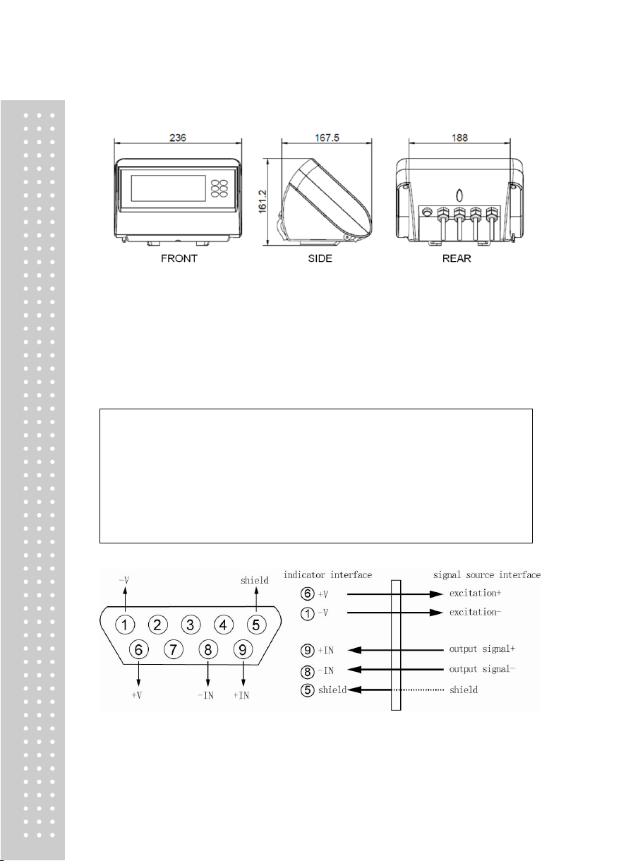
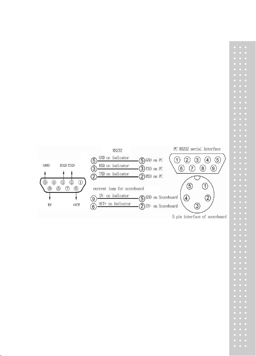
1. Serial communication
The indicator gets into self-check process after the power supply is connected. If the weight
on platform is withinthe startup zero setting range, it will enter automatic zero, and then the
weighing status. If the weight on platform exceeds thezero setting range, the indicator will
give tips and display weight.
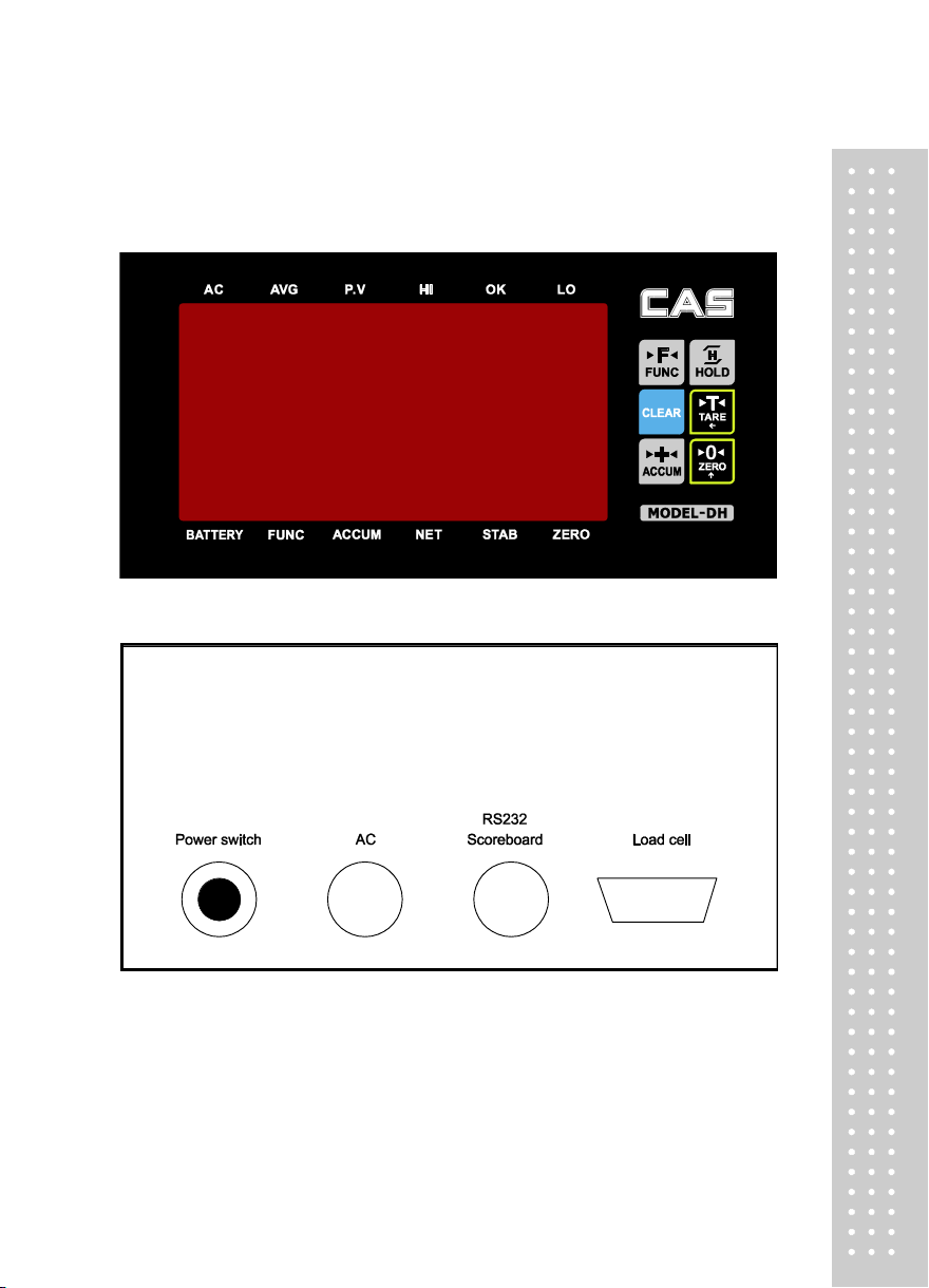
2. key Operation
Inthecalibrationandparametersettingstatus,somekeyswillperformthefollowingfunctions:
1)[ZERO]keyperformsthe"plus1"function.Afterthe[ZERO]keyispressed,thenumberdisplayed
inthelastbitwillbe"plus1",automaticzerowillbemadeafteritisaddedto9.
2)[TARE]keyperformsthe"shift"function.AftertheTAREkeyispressed,thenumbershowninthe
lastbitwillmovetotherightforonebit,andwillmovetothehighestbitautomaticallyafterpresstare
keywhenitisinthelastbitattheright.
3)[HOLD]key performs“input” function, after the [HOLD]keyispressedthedatewillbeinputto
indicatorwhichwasset.
4)[CLEAR]keyperforms"exit"function,after[CLEAR]keyispressedtheindicatorwillexitthe
calibrationstateorsettingstate.
5)[ACCUM] keyperforms“switchingparameter"function,afterthe[ACCUM] keyispressedthe
indicatorwillcomeintothenextparametersettingstate.
3. Weighing Operation
1) ZERO :
Press [ZERO] key to enable the data within zero setting range of indicator to return to zero.
Zero setting can be performed only after the STABLE light is on.
2) TARE :
When thedisplayedweightinweighingstatusispositiveandtheSTABLElightison,pressthe
[TARE]keytodeducttheindicatedweightastareweight.Inthiscase,theindicatorwillshowanet
weightof"0"andtheNETWEIGHTlightison.Pressthe[TARE]keyagainwhengrossweightis0,
theindicatorwillclearthetareweightvalue.
Note: Tare is not workable when gross weight isnegative number.
①Inner code checking
Press [HOLD] and [ACCUM] key togetherin the normal weighing status, theindicator
willdisplaythe inner code.
②HOLD, average value :
You can choosethisfunctionbyfunctionsettingP2.Youcanstartorstopthisfunctionby[HOLD]
keyafteryourchoosethisfunction.
Choose2 for P2 parameter, press [HOLD]key, average valuelight is on, now the indicator
can estimateautomatically, and after stabilization theindicator will calculate and display
average value, and will display the average value after lighting, and also will cancel
displayaveragevalueaftercurrentvaluebacktozero,nowcanweighthenextaveragevalue;
Choose3forP2parameter,press[HOLD]keyinnormalweighingstatusandpeakvaluelightison,
andindicatornowintheautopeakvalueworkingstatus,anditcankeepthemaximumweighing
data,andwillcancelthedataholdaftertheweightbacktozero.
Inaboveoperationsteps,wecancanceltheaverageorholdfunctionbypress[HOLD]keyanytime;
andwillstartthisfunctionafterpress[HOLD]keyeverytimewhenstartup.