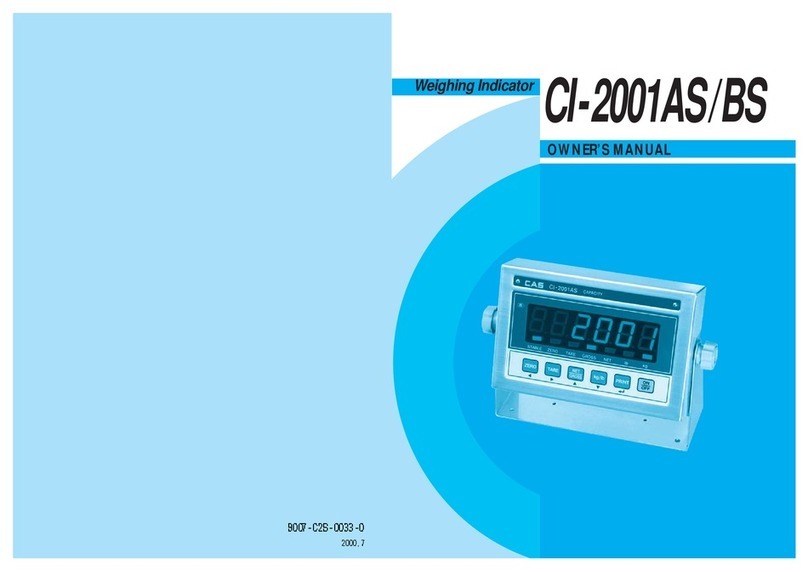
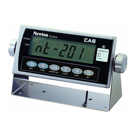
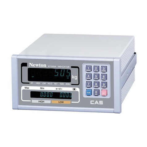
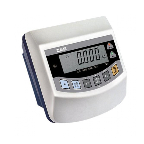
CAS CI-400 Series User manual

`
2

3
Cautions forYour Safety
Please comply with 'Cautions for Your Safety', which will lead you to use the product safely and
properlytopreventanydangeroussituations.
■Cautionsaredividedinto'Warning'and'Alert',whichmeanasfollows.
■Keepthismanualinaplacewhere productuserscanfindout, afterfinishreadingit.
'Warning' means a greatpossibility ledto thedeath orheavy injury when instructionsare violated.
'Alert'means a great possibility led tothe injury or materialdamage when instructions areviolated.

`
4
Warning
Never disassemble,repairorretrofit the
product.
Itmightexcludetheproductfromthe
qualityassuranceandcausethe damage
todevices,electricshockorfire.
Ensure thepowerplug to befully
insertedtopreventshaking.
Any instableconnectionmight cause
electric sparks tosetfire.
Ensure the groundingofthe product.
Poorgroundingmight causefailureor
electricshockupon electricleak.
Donotdamage,process,excessively
jerk,bend ortwistthe powercord.
Itmightdamage the powercordto
causefireor electric shock.
Keep anycombustible sprayorfire
sourceaway.
Itmightcausefire.
Do not spraywatertothe outside of the
product or useitinanyhumid place.
Itmightdeterioratetheinsulationof
electric parts that can cause the electric
shock,fireriskorweighing errors.
Donotplacetheproducttothedirect
sunlight ornearanyhotobjectlike
a heater.
Itmightcausefire.

5
Attention
Checktheweighingerroranytime for
the accurateweighing.
Any useoutoftheallowedtolerance
forthe carelessuseor othercauses
mightnotensure theaccurate
weighing.
Avoidany suddenshock tothe product.
Itmightdamage the producttofailthe
accurateweighing.
Find aproperplacetoattachtherubber
padatthebottomoftheindicator,
whichwas shippedtogether.
Donotusetheproductataplacewith
sudden temperature changes or severe
vibrations.
Itmightcausetheweighingerroror
failure.
Do not installthe produce at aplace withthe excessive electromagnetic wave.
Itmightcausethewrongweighing.
OurDealers :CAS feelsthat each of its valued customers should getthe best service
available. Whether it’s the initial installation of our product,
maintenance/repair work, or simplyansweringquestions about our products,
CAS Corporation and all of itsAuthorized Dealersare highly trained to assist
you with anyneed regardingCAS products.

`
6
Contents
1. Features.................................................................................8
1-1. Features...........................................................................................8
1-2. Main Functions..............................................................................8
1-3. Analog andA/D Conversion........................................................9
1-4. Digital and Display........................................................................9
1-5. Product Specifications.................................................................10
1-6. Standard Specification................................................................10
1-7. Option Specification....................................................................10
2. Specifications inAppearance.....................................................11
2-1. External Dimension.....................................................................11
2-2. Front Panel Descriptions.............................................................12
2-3. Keyboard......................................................................................15
2-4. Rear Panel Descriptions..............................................................17
3. Installation & Connection...........................................................18
3-1. Loadcell Connection...................................................................18
4. Weight Setup(Calibration) Mode...........................................20
4-1. Weight Setup(Calibration) Menu...............................................21
4-2. Howto Seal the Indicator(Sealing)............................................30
5. Weighing Mode..................................................................................31
6. Test Mode..............................................................................................35
7. Set Mode................................................................................................40
8. OPTION................................................................................................93
8-1. Relay In4 / Out6...........................................................................93
8-2. Analog Out...................................................................................95
8-3. BCD-OUT....................................................................................97
8-4. BCD-IN........................................................................................99
9. Serial Communication...............................................................101
9-1. RS-232CPort Connection....................................................... 101
9-2. Current loop .............................................................................. 102
9-3. RS-422/RS-485 Serial Communication (Option)................. 103
10.Appendix..........................................................................................104
11. ErrorMessage................................................................................116
11-1. ErrorMessagefromtheWeightSetupMode............................116
11-2. ErrorMessagefromtheWeighingMode..................................117

7
Preface
Thankyou very much forpurchasing CASInternationalIndicator.
This produce is characterized by the excellent performance and luxurious features through
strict examinations, as well as elaboration for each part under our strict quality control.
CAS Indicator (CI-series) is a product with rich functions and various external interfaces,
which is designed to comply well with special requirements in a variety of industrial fields
under strong andbeautiful designs in appearance.
In addition, it is designed for the user-friendly programs for the easier use of indicator by any
user with thebuilt-in messagedisplayfunctions to helpusersunderstand the product.
Please use the product right and sufficiently utilize functions of CI-400 series as you read this
manualthoroughlybefore using CI-400 series.

`
8
1.Features
1-1. Features
■ High speed, High accuracy
■ High speed micro processor adoption
■ A/D conversion speed : Maximum 200 times/sec
■ Appropriate for weight and measurement system
■ Easy operation and various options.
■ Simple and prompt Full Digital Calibration
(SPACTM:SinglepassautomaticspanCalibration)
■ RFI./EMI screened
■ Watch Dog circuitry (System restoration)
■ Weight Back-up
(Weightmemoryatsuddenpowerfailure)
1-2. Main Functions
■ Store date, time and calculated data at sudden power failure
■ Variousspecificationonweightconversionspeed.
(Digitalfilterfunction)
■ Variousprinterconnection.(RS-232CSerialprinter)
■ Tareweightsettingwithkeys
■ Storageofmeasuredtimes.
■ SetPointinput&highest,lowestlimitinput
■ Externalinput4relay.(CI-405,CI-407)
■ Externaloutput6relay.(CI-405,CI-407)
■ Userscansetthedesirousmax.weightandadivisionfreely
■ Controlvariousexternalequipmentbyinnerexternalinput/output.(option)
■ Printdateandtimebyinnerclock
■ SelfhardwareTest.
■ PromptA/SisavailableforTestofeachpartofcircuitbymoduleispossible.

9
1-3. Analog andA/D Conversion
Inputsensitivity
0.3 uV/D(Certification), 0.2 uV/D(None)
Zeroingrange
0 ~ 2 mV/V
Loadcellsupplyvoltage
DC 5V
Maximumsignalinputvoltage
3.0mV/V
Zerovariationwithtemperature
ZERO : ±10 PPM / ℃
SPAN : ±10 PPM / ℃
InputNoise
±0.6㎶P.P
InputImpedance
10 ㏁
A/Dconversion method
∆∑
A/Dresolution
1,000,000 Count(20bit)
A/Dconversion speed
350 rounds / Sec
Non-straightness
0.01 % FS
1-4. Digital and Display
Span Calibration
FullDigitalCalibration(SingleautomaticspanCalibration)
Display
7-Segment3 DigitsRedFND2EA
(Font:11(W)X20(H)mm)
7-Segment3 DigitsRed FND8EA(CI-405,407)
(Font: 4(W)*8 (H)mm)
Key
Number Key and Function Key (15EA)
Division
X1, X2, X5, X10,X20,X50
DisplayBelowZero
“-”minus
Tare Subtraction
Fullcapacity
Sign forstatus
Stable,Zero,Tare,Gross/Net,Auto,Print,Hold,RX,TX(CI-401)
Stable,Zero,Tare,Gross/Net,SP1,SP2,SP3,SP4,Comm
(CI-405,CI-407)

`
10
1-5. Product Specifications
Power
SMPS-AC 100-240V~,50-60 Hz,0.2A
Product Size
185(W) x102(D) x92(H)
Temperature Range
-10 ℃~+40 ℃
Product Weight
Approx.1.2kg
Fuse Capacity
0.5AL250 V
Power Consumption
Approx.3.9W
1-6. Standard Specification
Standard-1
RS232 Interface(Port1,Port2)
Standard–2
CurrentLoopInterface
Standard–3
ExternalInput(Input4)
1-7. Option Specification
Option-1
AnalogV-out (0-10 V)orI-out(4-20 mA)
Option-2
BCDOut
Option-3
BCDIn
Option-4
Relay moduleType1(Input 4, Output 6)
Option-5
RS-422/485 Interface
*Ensuretoaffirmbeforepurchasingtheproductsincetheremaybealimitationfortheoptionmodulethatcanbeused
dependingontheprogramversion.

11
2. Specifications in Appearance
2-1.ExternalDimension

`
12
2-2. Front Panel Descriptions
■CI-401
DisplayInformation
LED
MainFunction
STABLE
Indicated when the weight is stable
ZERO
Indicated when the weight is “0”
TARE
Indicated when tare is entered
G/N
Indicates gross and net weight after setting tare
AUTO
Indicated when the Data Print-out is Automatic during Stable Weight
PRINT
Indicated during data transmission to an External Print communication Port
HOLD
Indicated when operating the hold function
RX
Indicates status of receiving data during communication
TX
Indicates status of transmitting data during communication

13
■CI-405
DisplayInformation
LED
Main Function
STABLE
Indicated when the weight is stable
ZERO
Indicated when the weight is “0”
TARE
Indicated when tare is entered
G/N
Indicates gross and net weight after setting tare
SP1
Indicated when Step1RelayONis output.
SP2
Indicated when Step2RelayONis output.
SP3
Indicated when Step3RelayONis output.
SP4
Indicated when Step4RelayONis output.
COMM
Indicatesstatusof transmittingorreceivingdataduringcommunication

`
14
■CI-407
DisplayInformation
LED
Main Function
STABLE
Indicated when the weight is stable
ZERO
Indicated when the weight is “0”
TARE
Indicated when tare is entered
G/N
Indicates gross and net weight after setting tare
SP1
Indicated when Step1RelayONis output.
SP2
Indicated when Step2RelayONis output.
SP3
Indicated when Step3RelayONis output.
FINISH
Indicated whenFINISH RelayONis output.
COMM
Indicatesstatusof transmittingorreceivingdataduringcommunication

15
2-3 Keyboard
Function Key
*Adjusttheweightdisplaynearthezero-setto0.
(2 %,5%,10%,20%,100%rangescanbeselected.)
* * For every press, alternate between total/net load and displaythe weight
withthelampindicator.
*Usethewhenweighingwiththecontainer.
*Pressthekeytosavethecurrentweightasthecontainerweight.
*Toremovethecontainerpressthekeywhentheloadboardisempty.
*Pressthekeytoprintthecurrentlydesignatedpowerformat.
*Usewhencheckingthesubtotalvalue(partialaggregate).
*Usewhencheckingthetotalvalue(aggregate).
*Usetochangetheproductnumber.
*Usetoinputtheitemcode.

`
16
*UsetochangetheSetPoint.
*Usewhenweighingamovingobject.
*Usetoenterthemenumode.
~
*Canbecustomizedtosuittheneeds.
Editor Key
~
* It enters 0~9 in the input numeric mode
*Usewhendeletingallinput.
*Usetoenterthemenumode

17
2-4. Rear Panel Descriptions
■ LOAD CELL : Port for connection.6Wires Loadcell
■ C/L : Current loop InterfacePort
■ RS-232 : Serial InterfaceCom Port (COM1, COM2)
■ RS-422/485:Serial Interface Com Port (RS-422/485)
■ AC INPUT : AC100 –240 V~ (50-60 Hz) ara available.
FUSE –T0.5AL250V
■ OPTION:When Option in Use, please connect.
■ EXT.INPUT:ExternalInputPort(INPUT:4)

`
18
3. Installation&Connection
3-1. Loadcell Connection
Connect theload cell connector tothe load cell port which is in the backside ofthe
indicator.
* Connection method
Note1. In case of4 wires load cell, connect EX+ with SEN+, and connectEX- with SEN-.
Note 2. Wire color can be different depending on the load cell’s manufacturer or it’s model.
* Relationship between the load cell output and input sensitivity.
The input sensitivityofthis product is maximum 0.2 uV/digit or more.
The following equation should be satisfied upon the systemdesign.
Pin
No
Pin
Function
Color
1
EXC+
RED
2
EXC-
WHITE
3
SIG+
GREEN
4
SIG-
BLUE
5
SHIELD
6
SEN+
BROWN
7
SEN-
BLACK

19
* Relationship between the load cell output and input sensitivity.
Example 1) Number of load cell: 4 ea
Rated capacityofload cell:500 Kg
Rated output ofload cell: 2mV/V
Value of a division:0.10 Kg
Applied voltage of load cell:5V(=5,000 mV)
According to the equation(5000 mV*2 mV * 0.1 Kg)/(500 Kg * 4) = 0.5 ≥ 0.2 uV
As the calculated value is greater than 0.2 uV, this weight systemdesign has no problem.
Note 3. It can checkthe mV/V value in the testmode3
Applied voltageofload cell x Output voltageofload cell xValueof adivision
0.2uV ≤ ------------------------------------------------------------------------------------------------
Rated capacity ofload cell xNumber of load cell

`
20
4. Weight Setup (Calibration) Mode
What isthe weight setup?
It refers to the calibration to setthe displayed value to the actual weight in displaying weights.
How toAccess to theWeight Setup Mode
Remove the blot on the rear panel and connect both of CAL pin(check picture below) And
turn on the power supply and push the keysame time, you can access to weight setup
mode
Pressthe keyintheweight setup modetoreturn to weighing mode

21
4-1. Weight Setup(Calibration) Menu (CAL1 –CAL9)
CAL 1 : Maximumcapacity calibration
CAL 2 : Minimum division calibration
CAL3 : Zero-set and span calibration
CAL4 : Hopper weight setting
CAL5 : Direct calibration
CAL6 : Zero adjustment
CAL7 : Factor calibration
CAL8 : Gravity adjustment
CAL9 : Setting dual range
CAL1
CAL1-1
Function: SettingUnit(Unit)
Rangeof setvalue:1~3
Used key
Display
Descriptions
Using numeric keys ~ Enter
Unit.
=Set, =Cancel
1. kg
Unit :kg
2. ton
Unit :ton
3. gram
Unit :g
CAL1-2 (Maximum capacity calibration)
Function:Setting MaximumValue
Rangeof setvalue: 1 ~99,999
Used key
Display
Descriptions
Usingnumerickeys ~
Entermaximumweight
=Set, =Cancel
C= 10000
Maxvalue=10000kg
C= 10
Maxvalue=10kg
Reference1.Themaximumcapacityoftheweighingscalecanmeasureanddisplay.
This manual suits for next models
3
Table of contents
Other CAS Accessories manuals

CAS
CAS NT-302A User manual

CAS
CAS CI-600D Series User manual

CAS
CAS CI-200 Series User manual

CAS
CAS CI-150A User manual

CAS
CAS WEIGHING SOLUTION NT-200 Series User manual

CAS
CAS CT100 Series User manual

CAS
CAS CI-170A User manual

CAS
CAS RW Series User manual

CAS
CAS EXP-2000A User manual

CAS
CAS CI-2001A User manual

CAS
CAS CI-502A User manual

CAS
CAS BI-100R User manual

CAS
CAS CI-1500 User manual

CAS
CAS SW II Series User manual

CAS
CAS CI-2400BS User manual

CAS
CAS CI-6000A Series User manual

CAS
CAS CI-100A Installation and operating instructions

CAS
CAS CI-2001AS User manual

CAS
CAS HDI User manual

CAS
CAS CI-2001A User manual