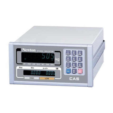
CAS CI-600D Series User manual

2

Cautions for Your Safety
Please comply with 'Cautions for Your Safety', which will lead you to use the product safely and
properly to prevent any dangerous situations.
■Cautions are divided into 'Warning' and 'Alert', which mean as follows.
■Keep this manual in a place where product users can find out, after finish reading it.
'Warning' means a great possibility led to the death or heavy injury when instructions are violated.
'Alert' means a great possibility led to the injury or material damage when instructions are violated.
3

Warning
Never disassemble, repair or retrofit the
product.
It might exclude the product from the
quality assurance and cause the damage
to devices, electric shock or fire.
Ensure the power plug to be fully
inserted to prevent shaking.
Any instable connection might cause
electric sparks to set fire.
Ensure the grounding of the product.
Poor grounding might cause failure or
electric shock upon electric leak.
Do not damage, process, excessively
jerk, bend or twist the power cord.
It might damage the power cord to
cause fire or electric shock.
Keep any combustible spray or fire
source away.
It might cause fire.
Do not spray water to the outside of the
product or use it in any humid place.
It might deteriorate the insulation of
electric parts that can cause the electric
shock, fire risk or weighing errors.
Do not place the product to the direct
sunlight or near any hot object like
a heater.
It might cause fire.
4

Attention
Check the weighing error anytime for
the accurate weighing.
Any use out of the allowed tolerance
for the careless use or other causes
might not ensure the accurate
weighing.
Customer Service:080-022-0022
Avoid any sudden shock to the product.
It might damage the product to fail the
accurate weighing.
Find a proper place to attach the rubber
pad at the bottom of the indicator,
which was shipped together.
Do not use the product at a place with
sudden temperature changes or severe
vibrations.
It might cause the weighing error or
failure.
Do not install the produce at a place with the excessive electromagnetic wave.
It might cause the wrong weighing.
Our Dealers : CAS feels that each of its valued customers should get the best service
available. Whether it’s the initial installation of our product,
maintenance/repair work, or simply answering questions about our products,
CAS Corporation and all of its Authorized Dealers are highly trained to assist
you with any need regarding CAS products.
5

Contents
1. Features...............................................................................9
1-1. Features........................................................................................ 9
1-2. Main Functions ...........................................................................9
1-3. Digital Loadcell Interface.........................................................10
1-4. Digital and Display ...................................................................10
1-5. General Specifications.............................................................. 11
1-6. Option Specifications................................................................ 11
2. Specifications inAppearance................................................... 12
2-1. External Dimension ..................................................................12
2-2. Front Panel Descriptions ..........................................................12
2-3. Keyboard ...................................................................................14
2-4. Rear Panel Descriptions............................................................17
3. Installation & Connection.........................................................18
3-1. Loadcell Connection.................................................................18
4. DLC Mode.........................................................................................19
4-1. DLC Mode Menu...................................................................... 19
5. Weight Setup(Calibration) Mode.......................................... 26
5-1. Weight Setup(Calibration) Menu ............................................. 26
5-2. How to Seal the Indicator(Sealing)..........................................37
6. Weight Mode.................................................................................... 38
6-1. Zero function ............................................................................. 38
6-2. Tare function..............................................................................39
6-3. Net Weight / Gross Weight Selection....................................... 40
6-4. Item Number Change................................................................41
6-5. Subtotal Print ............................................................................. 41
6-6. Total Print...................................................................................42
6-7. Selection and Change of Article Information.......................... 43
6-8. How to Change Item Number..................................................43
6-9. Change in Tare Weight.............................................................. 44
7. Test Mode........................................................................................... 45
6

8. Set Mode...............................................................................................50
8-1. How to Enter the Set Mode ......................................................50
8-2. General Functions......................................................................53
8-3. Communication and Function Setting .....................................59
8-4. Print Function Setting................................................................64
8-5. Option Setting............................................................................69
8-6. Hardware Set Function..............................................................70
9. RS-232C Interface in Detail.....................................................72
9-1. RS-232C Port Connection ........................................................72
9-2. How to Connect an Auxiliary Display.....................................73
9-3. How to Connect a Label Printer(DLP) ....................................73
9-4. RS-422 & 485 Serial Communications ...................................74
10. Serial Data Information...........................................................75
10-1. CAS 22Bytes Format..............................................................75
10-2. CAS 10Bytes...........................................................................75
10-3. AND 18Bytes ..........................................................................75
10-4. CAS 22Bytes with relay status...............................................76
11.Appendix..........................................................................................77
12. Modbus Protocol..........................................................................80
13. Error Message...............................................................................85
13-1. Error Message from the Weight Setup Mode.............................85
13-2. Error Message from the Weighing Mode...................................86
7

Preface
Thank you very much for purchasing CAS International Indicator.
This produce is characterized by the excellent performance and luxurious features through
strict examinations, as well as elaboration for each part under our strict quality control.
CAS Indicator (CI-series) is a product with rich functions and various external interfaces,
which is designed to comply well with special requirements in a variety of industrial fields
under strong and beautiful designs in appearance.
In addition, it is designed for the user-friendly programs for the easier use of indicator by any
user with the built-in message display functions to help users understand the product.
Please use the product right and sufficiently utilize functions of CI-600 series as you read this
manual thoroughly before using CI-600 series.
8

1. Features
1-1. Features
■High accuracy
■High speed micro processor adoption
■Appropriate for weight and measurement system
■Easy operation and various options.
■Simple and prompt Full Digital Calibration
(SPACTM: Single pass automatic span Calibration)
■RFI./EMI screened
■Watch Dog circuitry (System restoration)
■Weight Back-up
(Weight memory at sudden power failure)
1-2. Main Functions
■Store date, time and calculated data at sudden power failure.
■Various specification on weight conversion speed.
(Digital filter function)
■Various printer connection. (RS-232C Serial printer)
■Tare weight setting with keys.
■Storage of measured times.
■Set Point input & highest, lowest limit input.
■External input 4 relay.(CI-605)
■External output 6 relay.(CI-605)
■Users can set the desirous max. weight and a division freely.
■Control various external equipment by inner external input/output.(option)
■Print date and time by inner clock.
■Self hardware Test.
■Prompt A/S is available for Test of each part of circuit by module is possible.
9

1-3. Digital Loadcell Interface
Applied voltage for load cell DC 9V
Loadcell connection Max. 10EA
Communication RS-485 half-duplex(COM2)
Baudrate 9,600BPS ~ 115,200BPS
Non-straightness 0.01% Full Scale
1-4. Digital and Display
Span Calibration Full Digital Calibration : SPAC™
(Single automatic span Calibration)
Display 4.3” Full Graphic LCD
Sign for status ZERO, TARE, NET,GROSS, STABLE, HOLD,
RX,TX,USB,UNIT(kg, lb, ton)
Division ×1, ×2, ×5, ×10, ×20, ×50
Tare Subtraction Full capacity
Display Below Zero “-”Minus
10

1-5. General Specifications
Power AC 85~264V, 50~60 Hz (20W)
Product Size 192(W) x 199(D) x 96 (H)
Temperature Range -10 ~ 40℃℃
Fuse Capacity T2A L250V
Product Weight Approx. 1.8 kg
1-6. Option Specification
Option - 1 Analog V-out (0 ~10V) or I-out (4~20mA)
Option – 2 Relay module
Option – 3 Relay module Type 2 (8in, 10out)
Option – 4 BCD Out
Option – 5 Ethernet
Option - 6 WiFi
Note 1. Ensure to affirm before purchasing the product since there may be
a limitation for the option module that can be used depending on
the program version.
11

2. Specifications in Appearance
2-1. External Dimension (CI-601D, CI-605D)
2-2. Front Panel Descriptions
12

Display Information
1. Display each DLC’s status (Green = OK, Red = NG)
2. 6Digits, Decimal point, sign
3. Unit : kg, lb, ton
4. Message Display : Key input, Error message..
5. Short cut key with function name
6. Set data SP1~4 (CI-605)
7. External input status (CI-605)
8. External output status (CI-605)
13

2-3. Keyboard
Function Key
* It sets the weight display near zero point to 0.
( Arange of 2%, 5%, 10%, 20% and 100% can be selected.)
* Use it to weigh with the tare.
* The current weight is memorized as the tare by pressing
the key.
* Press the key when the load tray is empty to release the tare.
* Use it change to item number or name
* Use it enter to menu mode.
* Some functions can be defined to the needs.
* Use it for the manual print. (default)
(The function set at M2120 in the Set Mode will be operated.)
* Some functions can be defined to the needs.
* Use it to fix the shaking weight(default)
(The function set at M2121 in the Set Mode will be operated.)
* Some functions can be defined to the needs.
* Use it to tare canceling. (default)
(The function set at M2122 in the Set Mode will be operated.)
1
4

Editor Key
~
* It enters 0~9 in the input numeric mode
* It enters A~Z , symbol in the input alphabet mode
,
* Use it to cursor up-down
,
* Use it to cursor left-right
* Use it to page up-downt
* Use it to erase privious charactor
* Use it to change input symbol
* Use it to correct any wrong input while entering data.
*Use it to enter a decimal point (.) in the calibration mode
* Use it to save input value.
15

Multi Function key
Numbers +
* Use it to change Item number.
Numbers +
* Use it to key tare function
*If the tare is known, enter it using the numeric keys.
(If the remaining value occurs when the input value is divided
into the minimum unit, the value is rounded and entered.)
+
* If F1 is set it for the manual print. You can use this
function
* Use it to print the subtotal print
(The base setting of F1 key is the Print key.)
Delete the total print data after printing will be progressed by
setting menu.
+
* If F1 is set it for the manual print. You can use this
function
* Use it to print the grandtotal print
(The base setting of F1 key is the Print key.)
Delete the total print data after printing will be progressed by
setting menu.
+
* Use it to clear subtotal data
+
* Use it to clear grandtotal data
16

2-4. Rear Panel Descriptions
CI-601D, CI-605D
□LOAD CELL : Port for connection. Digital Loadcell
□COM 1 : Serial Interface Com Port (Option - RS485)
□COM 2 : Serial Interface Com Port
□OPTION : When Option in Use, please connect.
□AC INPUT : AC 100 ~ 240V(50/60Hz) ara available.
FUSE - T2A L250V
17

3. Installation & Connection
3-1. Loadcell Connection
Connect the load cell connector to the load cell port which is in the backside of the
indicator.
* Connection method
Pin Function Color
1 Power Red
2 RX+ Brown
3 GND White
4 RX- Black
5 TX+ Green
6 TX- Blue
7 SHIELD Shield
Note 1. Wire color can be different depending on the load cell’s manufacturer or it’s model.
1
8

4. DLC Mode
What is the DLC mode?
Using a digital loadcell to turn on the necessary capabilities and failure to perform diagnostics
mode
How to Access to the DLC Mode
Push the in the weighing mode, by the key to select DLC mode
Push the key in the DLC mode to return to weighing mode.
4-1. DLC Mode Menu
CODE Menu CODE SubMenu
4100 Set Number of DLC Used
4211 Set ID of DLC
4212 Set ID Automatically
4200
4220 Set ID(Using the serial number)
4310 Scale View
4300 4320 Detail View
4410 Check Comm. error status
4400 4420 Diagnostic of DLC
4510 Check Dlc’s Information
4500 4520 DLC Information Read & Save
4000 DLC Mode
4600 Set Dlc’s Parameters
19

Menu-4100
Function Set Number of DLC Used
Display Part Meaning
Set Range
(1 ~ 10) Set Value : XX
Initial Value : 1
Setting the number of DLC Used
(EX _ 1 = Use 1 DLC
(EX _ 8 = Use 8 DLC)
Note 1. Is possible to use up to 10, If you are not connected by the number set to display
Error message.
Menu-4211
Function Set ID of DLC
Display Part Meaning
Set Range
(1 ~ 10) Set Value : XX
Initial Value : 1
EX _ 1 = Currently connected to the DLC’S ID is set to ‘1’
EX _ 8 = Currently connected to the DLC’S ID is set to ‘8’’
Note 1. When use this function, you will need to connect only a single loadcell.
Menu-4212
Function Set ID automatically(for maintenance)
Display Part Meaning
Set Range
- - this function is find the DLC what has no ID,
and set ID to that automatically
Note 1. If you have to replace a loadcell , then use this function.
-First, you need to replace the loadcell. Then you need to run this function.
-The indicator automatically finds a new loadcell and set up new ID to a new loadcell
Note 2. When connect two or more new loadcell, this function should not be running,
20

Menu-4220
This function useful, when set DLC’s ID using DLC’s serial number.
Function Choose the loadcell type
Display Part Meaning
ᆷ1_No Name Digital Module or another digital loadcell
ᆷ2_WBK-D WBK-D Loadcell
Set Range
(1 ~3)
ᆷ3_DSB-D DSB-D Loadcell
Note 1. DLC’s serial number consist of 14 Digits
Note 2. If know every DLC's serial number, can set DLC’s ID easier.
Function : Set DLC’s ID using serial number
Use Keys Display Part & Description
=Set
= Cancel
=
Choose position
Ex) Set ID to 1 to one of loadcell
1. Edit position move to ID_1, using , keys and press
“enter” key.
2. Input the serial number to set ID
3. If ID setting was completed successfully. Lamp color is change to
green
21
Table of contents
Other CAS Accessories manuals

CAS
CAS CI-6000A Series User manual

CAS
CAS CI-150A User manual

CAS
CAS SW II Series User manual

CAS
CAS EXP-2000A User manual

CAS
CAS CI-400 Series User manual

CAS
CAS CI-170A User manual

CAS
CAS CI-100A Installation and operating instructions

CAS
CAS CI-2001AS User manual

CAS
CAS NT-302A User manual

CAS
CAS CI-1500 User manual

CAS
CAS CI-2001A User manual

CAS
CAS CI-200 Series User manual

CAS
CAS CI-502A User manual

CAS
CAS CI-2001A User manual

CAS
CAS CI-2400BS User manual

CAS
CAS RW Series User manual

CAS
CAS WEIGHING SOLUTION NT-200 Series User manual

CAS
CAS CT100 Series User manual

CAS
CAS BI-100R User manual

CAS
CAS NT-500 Series User manual