CAS CASTON II User manual

CASTON
1 5/13/201420
CASTON SERVICE MANUAL
(CASTON II & CASTON III & CASTON III PLUS)

CASTON
2 5/13/201420
< Table of Contents >
1 Classification ...................................................................................................................................... 4
1.1. Preface ................................................................................................................................... 4
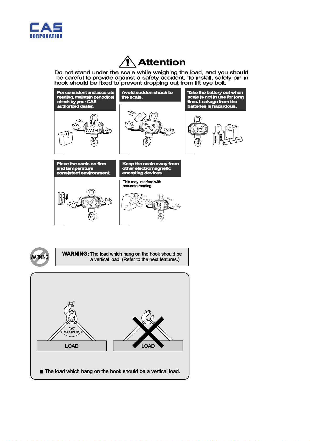
1.2. Precaution ............................................................................................................................. 4
1.3. Specification .......................................................................................................................... 6
1.4. Sealing Method ..................................................................................................................... 9
2 Classification .....................................................................................................................................13
2.1. Overall View.........................................................................................................................13
2.2. Display & Key Functions .....................................................................................................14
2.3. Options .................................................................................................................................15
2.3.1. Remote Control ...........................................................................................................16
2.3.2. TW-100 (Option) .........................................................................................................17
2.3.3. TWN (Option) .............................................................................................................18
2.4. Battery Usage .......................................................................................................................19
2.5. Use of Battery Charger ........................................................................................................21
3 Getting Started ..................................................................................................................................22
3.1. AP MODE ............................................................................................................................23
3.2. SLEEP MODE .....................................................................................................................23
3.3. BA MODE ............................................................................................................................24
3.4. CO MODE ...........................................................................................................................24
3.5. ID MODE .............................................................................................................................25
3.6. BR MODE ............................................................................................................................25
3.7. OP MODE ............................................................................................................................25
3.8. CH MODE ...........................................................................................................................25
3.9. PANID MODE .....................................................................................................................26
3.10. HL MODE ............................................................................................................................26
4 CASTON III Command Mode Protocol ........................................................................................27
5 Calibration.........................................................................................................................................29
5.1. General Calibration .............................................................................................................29
5.1.1. C4 Setting ....................................................................................................................31
5.1.1.1. C4-1 Setting................................................................ 31
5.1.1.2. C4-2 Setting................................................................ 31
5.1.1.3. C4-3 Setting................................................................ 31
5.1.1.4. C4-4 Setting................................................................ 31
5.1.1.5. C4-5 Setting................................................................ 31

CASTON
3 5/13/201420
5.1.2. SPAN Calibration Setting (C-3) ..................................................................................31
5.1.3. Gravity Constant Value Setting (C-9) ........................................................................31
5.1.4. Calibration factor Setting (C-10) ................................................................................32
5.1.5. Displaying Real A/D Value (C-5) ................................................................................33
5.1.6. Input Function Key Code (C-6) ..................................................................................33
5.1.7. Percent Calibration (C-7) ............................................................................................33
5.1.8. Battery Calibration (C-8) ............................................................................................33
6 The Schematics and Diagram ...........................................................................................................34
6.1. System Block Diagram .........................................................................................................34
6.2. Circuit Diagram ...................................................................................................................36
7 Exploded View ...................................................................................................................................42
8 Part Location .....................................................................................................................................55
9 Error Messages & Solution ...............................................................................................................60
10 Part List (Common Part) ..................................................................................................................61
11 Part List (ETC Part) .........................................................................................................................94

CASTON
4 5/13/201420
1 Classification
1.1. Preface
Thank you for purchasing of our CAS scale.
This scale has been designed with CAS reliability, under rigid quality control
and with outstanding performance.
WE hope that your departments enjoy with high quality of CAS product.
This manual will help you with proper operations and care of the CASTON series.
Please keep it handy for the future references.
1.2. Precaution

CASTON
5 5/13/201420

CASTON
6 5/13/201420
1.3. Specification
-CASTON II
CASTON II
Capacity /
Division(kg)
500 / 0.2 1000 / 0.5 2000 / 1 3000 / 2 5000 / 2
Internal
Resolution 1 / 60,000
MAX External
Resolution 1 / 3,000
Display Four LEDs with 5 digit(1.2 inch)
POWER 6V/7AH(PB BATTERY)
Keys ON/OFF, *(STAR), ZERO, TARE, HOLD
Function
Weighing
AUTO POWER OFF
HOLD
Remote control
Wireless communication(option)
Operating
Temperature
- 10 C ~ +40 C
Options Remote control

CASTON
7 5/13/201420
-CASTON III
CASTON III
Capacity /
Division(kg)
500
/0.2
1000
/0.5
2000
/1
3000
/1
5000
/2
10000
/5
15000
/5
20000
/10
30000
/10
Internal
Resolution 1 / 60,000
MAX External
Resolution 1 / 3,000
Display Four LEDs with 5 digit(1.5 inch)
POWER 12V/7AH(PB BATTERY)
Keys ON/OFF, *(STAR), ZERO, TARE, HOLD
Function
Weighing
AUTO POWER OFF
HOLD
Remote control
Wireless communication
Operating
Temperature
- 10 C ~ +40 C
Options Wireless Communication - Bluetooth method

CASTON
8 5/13/201420
-CASTON III PLUS
CASTON III PLUS
Capacity /
Division(kg)
- - 2000
/1
3000
/1
5000
/2
10000
/5
15000
/5
20000
/10 -
Internal
Resolution 1 / 60,000
MAX External
Resolution 1 / 3,000
Display Four LEDs with 5 digit(1.5 inch)
POWER 12V/7AH(PB BATTERY)
Keys ON/OFF, *(STAR), ZERO, TARE, HOLD
Function
Weighing
AUTO POWER OFF
HOLD
Remote control
Wireless communication
Operating
Temperature
- 10 C ~ +40 C
Options Wireless Communication - Bluetooth method

CASTON
9 5/13/201420
1.4. Sealing Method
-CASTON II

CASTON
10 5/13/201420
-CASTON III

CASTON
11 5/13/201420
-CASTON III PLUS

CASTON
12 5/13/201420

CASTON
13 5/13/201420
2 Classification
2.1. Overall View
-CASTON II
-CASTON III

CASTON
14 5/13/201420
-CASTON III PLUS
2.2. Display & Key Functions
■ DISPLAY
WEIGHT DISPLAY: Displays weight or messages (5 Digit).
ZERO LAMP: Indicates that scale is stable and at zero.
NET LAMP: Indicates that scale is currently using a tare.
HOLD LAMP: Indicates that the HOLD function is activated.
LOW BATTERY LAMP: Indicates that voltage of battery low and should be changed soon.
■ KEY FUNCTIONS
KEYS FUNCTIONS
Used to turn the scale ON / OFF or used to released from
AP/HL mode
Used to reset the scale zero or enter the AP mode
Used to activate tare function and to clear tare entry
Used to weigh unstable things (livestock, liquid, etc.) or used to
store the set value in ‘AP/HL’ mode
Used to increase the set value in ‘AP/HL’ mode
EYE BOLT
DISPLAY
KEYBOARD
HOOK
LOAD HOUSING
LOW BATTERY
LAMP

CASTON
15 5/13/201420
2.3. Options
Please refer to handy terminal TW-100 B manual of CASTON-III B
(Crane Scale : Bluetooth Type)
1. TW-100 Specification
Frequency 2400~2483.5 MHz
Channel interval 1 MHz
Channel 78 channel
Communication
Type GFSK(Gaussian Frequency Shift Keying)
Communication
Speed 9600
Actual
Communication
Distance
Maximum. Approximately 50~100M
Display LCD (5 digit)
Size of letter 12 mm (Height)
Display below zero
“-“ displayed
Battery life time Approx. 6 hours
Battery charging
time Approx. 3~5 hours
Power TW -100 : Rechargeable DC Battery7.2V750mA
Charger : AC220V/60Hz
Power
consumption 0.43~0.72 W
Temperature range
-10 ~ +40℃ ℃
Function Printer interface, zero, tare, hold, print,
ID setting, weight sum

CASTON
16 5/13/201420
2.3.1. Remote Control
■ ON/OFF: Button to operate power on/off.
■ ZERO: Button to correct zero value.
■ TARE: Used to tare value memorizing.
■ HOLD: Used to weigh moving thing.
■ CLEAR : Used to clear summing weight.
■ SUM : Used to sum item
REMOTE CONTROL
AVAILABLE
DISTANCE 6m ~ 9m
AVAILABLE ANGLE
60°
POWER 3V(1.5V AMM x 2)

CASTON
17 5/13/201420
2.3.2. TW-100 (Option)
Please refer to handy terminal TW-100 B manual of CASTON-III B
(Crane Scale : Bluetooth Type)
(1). TW-100 Specification
Frequency 2400~2483.5 MHz
Channel interval 1 Mhz
Channel 78 channel
Communication
Type GFSK(Gaussina Frequency Shift Keying)
Communication
Speed 9600
Actual
Communication
Distance
Maximum. Approximately 50~100M
Display LCD (5 digit)
Size of letter 12 mm (Height)
Display below zero
“-“ displayed
Battery life time Approx. 6 hours
Battery charging
time Approx. 3~5 hours
Power TW -100 : Rechargeable DC Battery7.2V750mA
Charger : AC220V/60Hz
Power
consumption 0.43~0.72 W
Temperature range
-10 ~ +40℃ ℃
Function Printer interface, zero, tare, hold, print,
ID setting, weight sum

CASTON
18 5/13/201420
2.3.3. TWN (Option)
Please refer to handy terminal TWN manual of CASTON Series
1. TWN Specification
Frequency 2.4GHz
Communication
methods ZIGBEE (BLUETOOTH)
Baud Rate 9600
Effective distance
for communications
Maximum about 50 ~ 100M
Display 320*240 TFT LCD
Display below zero
“-” minus signal
Battery life time Approx. 24hours
Battery changing
time Approx. 5 ~ 6 hours
Power
TWN : Rechargeable DC Battery 3.7V
Charger: adapter for charging (4.2V 4400mA)
Temperature range -10℃ ~ 55℃
Function
Printer interface, zero, tare, hold, print
ID setting, weight sum.

CASTON
19 5/13/201420
2.4. Battery Usage
- CASTON II
■ Couple connector in main body with connector in battery portion.
■ Insert battery portion to the main body and turn fixing bolt to the right to fix.
■ If the battery is neglected for a long time or not use without charging,
it may effect on battery life. (recommended charging period : once a month)
■ To prevent battery discharge, CASTON-II is disconnected with the battery.
■ Please connect the battery to use after opening the product as shown above.
1
Check the
battery case.
2
Loosen both of bolts.
3
Disconnect the Battery case.
4
Check the connector which
can hook up the body to the
battery.
5
Hook up the body to the
connector of the battery
case.
6
Push the battery case in the
body and then tighten the
bolt.

CASTON
20 5/13/201420
-CASTON III
■ Open the battery lid located in back of the scale and turn main switch off.
■ Separate the battery connector and take out the discharged battery.
■ Put a charged battery in rear and connect the battery connector.
Turn main power switch on and cover the battery lid.
■The drop of battery voltage can affect the brightness of display.
To prevent this, the regular battery recharging is recommended.
■In case the battery will be left without recharging for a long time,
it is desirable the main power switch is set off.
Otherwise, it also can affect the battery life.
-CASTON III PLUS
■The drop of battery voltage can affect the brightness of display.
To prevent this, the regular battery recharging is recommended.
■In case the battery will be left without recharging for a long time, it is
desirable the main power switch is set off. Otherwise, it also can affect
the battery life.
Other manuals for CASTON II
1
This manual suits for next models
2
Table of contents
Other CAS Scale manuals