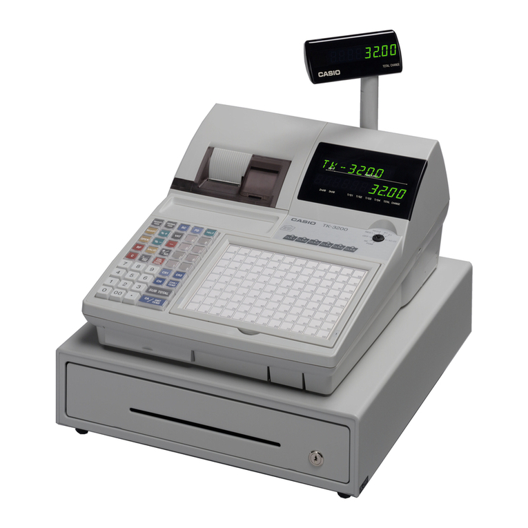
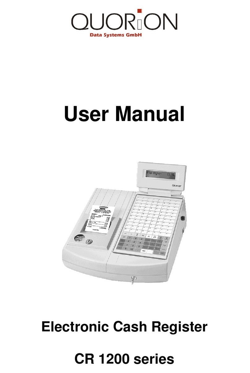
Casio TE-7000S User manual

CONTENTS
TE-7000S/8000F/8500F PAGE
1. SPECIFICATIONS........................................................................................ 1
2. CONNECTOR LOCATIONS ........................................................................ 4
3. MACHINE INITIALIZATION ......................................................................... 5
4. DISASSEMBLY............................................................................................ 9
5. CIRCUIT EXPLANATION .......................................................................... 17
6. OPTION INSTALLATION........................................................................... 34
7. IN LINE ....................................................................................................... 36
8. ON LINE ..................................................................................................... 39
9. DIAGNOSTIC OPERATION....................................................................... 41
10. ERROR CODE LIST................................................................................... 65
11. IC DATA ..................................................................................................... 70
12. PCB LAYOUT ............................................................................................ 76
13. CIRCUIT DIAGRAMS................................................................................. 80
14. PARTS LIST............................................................................................. 103
To prevent malfunctions caused by the weak batteries, charge the memory
protection batteries for over 12-hours before installation or after a long-time
vacation (over 30 days).
•Before installation, initialize the terminal and leave it turn on over 12-hours.
•After a long-time vacation, initialize the terminal and restore the program data if
the terminal is in malfunction, and leave it turn on over 12-hours.
•Over 48-hours charging makes the batteries fully charged.

— 1 —
• CPU Name HD6417706AF133
Number of control bit 32 bit
Internal RAM 16 KBytes
• DRAM Name MD56V62160E-10TAB0
Capacity 64 Mbits (8 MBytes)
• Flash ROM Name MBM24DL324BE90PFTN
Capacity 4 MBytes
• I/O controller Name uPD784215AGC-XXX-8EU
• Gate array Name uPD65945GJ-P16-JEU
• LCD controller Name S1D13705F00A100
• ARCNET controller Name COM20019ILJP
• Switching power supply Name SPS-468
• LCD unit Name KCG057QV1DB-G00
• Inverter unit Name PS2-70052-001
• Themal printer Name M-T203A-001(receipt)
M-T203-001(journal)
Print method Impression heat line dot
Head specification Total dot number : 432 dots/dot line
Dot pitch : Length 8 dots/mm
Wide 8 dots/mm
Paper cut Auto-paper cut
Paper supply method Drop-in paper loading
• Roll paper Type Heat-sensitive paper
Size 57.5±0.5mm
Roll diam φ 83 or less
Thickness 75±3µm
1. SPECIFICATIONS
1-1. Electrical specifications
1-2. Environmental specifications
1-3. Main components
• Operating temperature 0 °C ~ 40 °C
• Operating humidity 10 % ~ 85 %
• Storage temperature -20 °C ~ 65 °C
• Storage humidity 10 % ~ 85 %
• Vibration strength 1.5 G (The machine must be in the carton box)
120 V 220 V 230 V 240 V
•Power consumption In operation Max. 0.9 A 0.6 A 0.6 A 0.6 A
stand-by Max. 0.15 A 0.15 A 0.15 A 0.15 A
•Memory protection Back-up battery VL3032/SGB (Vanadium lithium battery)
Back-up period 30 days (25 °C)
Battery life Replace the battery every 5 years.
Recharge time 48 hours (full charge)
•Clock & Calendar Accuracy Within ±30 sec. per month (25 °C)
Auto calendar Effective until 2099 A.D.

— 2 —
1-5. Drawer List
BDGCDC
M DL-2783 D-19BC-B84M-9* X X
M DL-2784 D-19BC-B84SM-9* X X
M DL-2424 D-19BC-B55SM-9* X X
M DL-2524 D-19BC-B64SM-9* X X
L DL-3616 D-11BH-B65SS-9* X X
L DL-3617 D-11BH-B65S-9* X
Note : Country code
B : Other countries G : Germany
D : En
g
land C : U.S.A./Canada
TE-8500F
Type Drawer Name Specification TE-7000S/TE-8000F
•Printer head 50 Km (anti-abrasion)
•Printer mecanical 6,000,000 hours
•Printer cutter 600,000 hours
•LCD 36,000 hours
•Backlight 36,000 hours
1-4. Duration of Life

—3 —
DEVICE NAME MODEL NOTE Applicable
•Clerk key kit CLK-K22
Dallas button for six people + a probe
Common
•Sheet holder kit SH-KIT10 A total of one sheet for No.3 &4 TE-8000F only
(including two sheets in solids)
•Multi drawer kit MDL-11 Number of additional units = 3 Common
•Remote display QT-2163D Com3 port only Common
•Option pole QT-2061S For Remote display Common
•Remote display cable QT-2162S Length 5m Common
•PC cable PRL-CB-2 Com1 port only Common
•Waterproof cover WT-77 TE-7000S only
•Waterproof cover WT-78/79
WT-78: for stroke / WT-79 : for touch
TE-8000F only
•Waterproof cover WT-62 TE-8500F only
•Slip printer SP-1300 Connect to Com2, 3 or 4 Common
Note :
The SP-1300 can be connected
one unit only.
•Slip printer cable PRT-CB-8C Length 1.5m Common
•Remote printer UP-250 Connect to Com2, 3 or 4 Common
•Remote printer UP-350 Connect to Com2, 3 or 4 Common
•Printer cable PRT-CB-8A Length 3m Common
•Printer cable PRT-CB-8B Length 5m Common
•Slip printer/ AC adaptor AD31U or E U: 100V/ E: 200V Common
•Power unit for External Printer PS-180 EPSON MODEL Common
•Power cord for power unit AC-170 EPSON MODEL Common
•Handy scnner HHS-15 Com2 port only Common
•Handy scnner HS1250 Com2 port only TE-7000S/
TE-8500F
•Laser scanner Quic Scan 6000 Com2 port only TE-7000S/
TE-8500F
•CF Memory Card SDCFB-xx-505 Common
•Modem
56k External Faxmodem
Common
“US Robotics”
•Modem 56k External Voice Common
Faxmodem “US Robotics”
•ISDN TA ELSA MICROLINK Only in Germany Common
TL-Pro (ISDN)
•Roll paper P-5880T Common
•Conversion kit CVK-S2/L2/LLL2/FS2 TE-7000S/
TE-8000F
1-6. Option List
CAUTION
Danger of explosion if battery is incorrectly replaced.
Replace only with the same or equivalent type
recommended by the manufacturer.
Dispose of used batteries according
to the manufacture’s instructions.
VORSICHT !
Explosionsgefahr bei unsachgemäßem Austausch der
Batterie.
Ersatz nur durch denselben oder einen vom
Hersteller empfohlenen gleichwertigen Typ.
Entsorgung gebrauchter Batterien nach
Angaben des Herstellers.
ADVARSEL !
Lithiumbatteri - Eksplosionsfare ved fejlagtig hándtering.
Udskiftning má kun ske med batteri
af samme fabrikat og type.
Levér det brugte batteri tilbage til leverandØren.

— 4 —
2. CONNECTOR LOCATIONS
COM3 Port
INLINE1 (ARCNET)
TERMINATORFORINLINE2
Ground Chassis
INLINE2(CAT5)IN
INLINE2(CAT5)OUT
COM2Port
COM1Port
COM4Port

— 5 —
3. Machine Initialization
3-1.How to initialize the terminal
Preparation: 1. All peripheral devices and terminals of this cluster should be
turned off.
2. Connect all of the peripheral devices (such as printer,
display etc.) to terminal.
3. Connect all terminals by in-line.
Operation: 4. Turn on all peripheral devices of a terminal.
5. Turn on this terminal with pressing the Journal feed key and
release the key after the “Copyright” window is shown.
6. After releasing the key, enter “20000” (U.S.)/ “10000” (other
area: English), “40000” (other area: German), “50000” (other
area: French), “60000” (other area: Spanish) and press the
<ST> key.
7. Enter the current date (YY/MM/DD order) and time and press
the <YES> key.
8. In ID character field, the auto-defined ID No. is shown.
We recommend that you should not change the value.
9. In this field, you can select “1. Master/2. Backup Master/3.
Satellite/4. Selfmaster.”
Please select one of these options and press the <YES> key.
Date 00-00-00
Time 12:34 00
ID Character MC #01
Check System Master
Check cluster ID 0
R/J/Order printer1 UP-350
R/J/Order printer2 UP-350
Slip Printer SP-1300
OK? YES
Date 01-10-10
Time 12:34 00
ID Character MC #01
Check System Master
Check cluster ID 0
R/J/Order Printer1 UP-350
R/J/Order Printer2 UP-350
Slip Printer SP-1300
OK? YES
Date 01-10-10
Time 12:34 00
ID Character MC #01
Check System Master
Check cluster ID 0
R/J/Order Printer1 UP-350
R/J/Order Printer2 UP-350
Slip Printer SP-1300
OK? YES
Date 01-10-10
Time 12:34 00
ID Character MC #01
Check System Master
Check cluster ID 0
R/J/Order Printer1 UP-350
R/J/Order Printer2 UP-350
Slip Printer SP-1300
OK? YES

—6 —
10. In this field, by pressing <YES> the check cluster No, should
be set, if your check tracking system are divided in some
clusters.
(Enter cluster No. “1”~ “9”, if you use check cluster system.)
11. In these fields, by pressing <YES> you can select, “1. No/2.
UP-350/3. UP-250”for R/J/Order printer.
Pleaseselectoneoftheseoptionsandpressthe<YES>key.
12. In this field, by pressing <YES> you can select, “1. No/2. SP-
1300”for slip printer.
Pleaseselectoneoftheseoptionsandpressthe<YES>key.
13. Pleaseconfirmallofthefieldandiftheyareallright,pressthe
<YES> key to proceed the next step.
14. If you want to download program data from other terminal or
CF card, select the appropriate menu and press the <YES>
key and proceed the next step.
Ifyoudon’tneedtodownloadanyprogramdata,justselect“1.
No Restore/Receive”and press the <YES> key.
If you have another machine to initialize, return to step 4.
Date 01-10-10
Time 12:34 00
ID Character MC #01
Check System Master
Check cluster ID 0
R/J/Order Printer1 UP-350
R/J/Order Printer2 UP-350
Slip Printer SP-1300
OK? YES
Date 01-10-10
Time 12:34 00
ID Character MC #01
Check System Master
Check cluster ID 0
R/J/Order Printer1 UP-350
R/J/Order Printer2 UP-350
Slip Printer SP-1300
OK? YES
Date 01-10-10
Time 12:34 00
ID Character MC #01
Check System Master
Check cluster ID 0
R/J/Order Printer1 UP-350
R/J/Order Printer2 UP-350
Slip Printer SP-1300
OK? YES
Date 01-10-10
Time 12:34 00
ID Character MC #01
Check System Master
Check cluster ID 0
R/J/Order Printer1 UP-350
R/J/Order Printer2 UP-350
Slip Printer SP-1300
OK? YES
INIT 10-10-01 12:34 000001
AUTO PGM
1. No Restore / Receive
2. PGM Restore (CF Card)
3. PGM Receive (Inline)

—7 —
Restore from CF card. 15. Insert the CF card into the slot and select the appropriate file
and press the <YES> key.
Pleaseselectoneoftheseoptionsandpressthe<YES>key.
16. Afterthe confirmation windowisshow, press the<YES>key
to proceed restoring.
After completion of downloading, return to step 4 to initialize
other terminals.
Program receive from other terminal.
15. In this field, by pressing <YES> you can select the receiving
contents as “1. All Data (including totalizer)/2. All PGM
(program only).”
16. In this field, by pressing <YES> you should enter the source
ID number of the data and press the <YES> key.
17. Please confirm all of the fields and if they are all right, press
the <YES> key to proceed downloading.
After completion of downloading, return to step 4 to initialize
other terminals.
INIT 10-10-01 12:34 000001
Data Restore
1. PLUPGM1 .004
2. PLUPGM2 .004
3. STORE-AA.090
4. STORE-BB.090
STORE-AA.090
Are you sure to restore?
INIT 10-10-01 12:34 000001
Receive Data All PGM
PGM Receive from MC #05
OK? YES
INIT 10-10-01 12:34 000001
Receive Data All PGM
PGM Receive from MC #05
OK? YES
INIT 10-10-01 12:34 000001
Receive Data All PGM
PGM Receive from MC #05
OK? YES

—8 —
How to initialize the terminal (add/replace one terminal)
Preparation: 1. All peripheral devices and terminals of this cluster should be
turned off.
2. Connect all of the peripheral devices (such as printer, display
etc.) to this terminal.
3. Connect the added/replaced terminal to inline.
Operation: Follow the steps shown on the page 1 to 3.
How to flag clear the terminal (or INIT2)
Preparation: 1. All peripheral devices and this terminal should be turned off.
2. Checkthe connectionofall peripheraldevices (such asprinter,
display etc.) of this terminal.
3. Check the connection of this terminal to inline.
Operation: 4. Turn on all peripheral devices of this terminal.
5. Turn on this terminal with pressing the “Receipt feed”key and
release the key after the “Copyright”window is shown.
6. After releasing the key, press the <ST> key.
7. Select “1. Flag Clear”and press the <YES> key.
The flag clear operation is finished.
Note:
Performing “Init 2”requires password “8888888888”and <YES>.
INIT
1. Flag Clear
2. Init 2
0.00

— 9 —
4. DISASSEMBLY
■UPPER COVER
1. Remove the key sheet. (TE-8000F only)
2. Remove the printer cover.
3. Remove the three screws.
Remove the upper case by sliding it forward.

— 10 —
4. Remove five connectors. (CN17, CN18, CN19, CN21, CN22)
Remove the screws and the earth cable.
■LCD ASS’Y
1. Remove the three screws.
Remove the mode key cover.
2. Remove the hinge cover.
3. Remove the three screws and two FPCs.
Remove the display case.
CN19 CN18
CN22
CN17
CN21
Mode key cover
Display case

— 11 —
4.
1Remove the screw and the earth cable.
5. Remove the two screws.
6. Remove LCD rear case.
NOTE: Be careful of the hooks when removing the LCD rear case.
7. Remove the slide knob.
2Remove the two screws.
3Remove the LCD ass’y. 2
1
3
Hooks

— 12 —
9. Remove the six screws.
10.Remove the LCD chassis.
8. Remove the five screws, four connectors and FPC.
Remove the inverter and PCB ass’y.
11.Remove the LCD unit.

— 13 —
■MODE KEY
1. Remove the two screws.
Remove the mode key.
2. Remove the two connectors and two FPCs.
3. Remove the four screws and the earth cable.
4. Remove the contact rubber and PCB ass’y (E468-E6).
■KEY BOARD ASS’Y
1. Remove the seven screws.
TE-8000F only

— 14 —
Remove the key board ass’y.
2. Remove the two screws.
Remove the PCB ass’y (E568-E42).
(TE-8000F only)
Remove two chassis.
Remove the eighteen screws.
Remove the FPC (E ), spacer (E ), and sheet.

— 15 —
■BATTERY
1. Remove the connector (CN6).
2. Remove the lithium battery.
■MAIN PCB ASS’Y
1. Remove the five screws, five connectors and three FPCs.
Remove the PCB ass’y (E468-1).

— 16 —
■PRINTER
1. Remove the six screws.
Remove the printer block.
■POWER SUPPLY
1. Remove the five screws.
Remove the four screws.
Remove the power supply.

— 17 —
5. CIRCUIT EXPLANATION
5-1. BLOCK DIAGRAM
NONE
QT-2163D/SP-1300 / UP-350 / UP-250
COM4 SP-1300 / UP-350 / UP-250
COM3
MDL-11
POWER SUPPLY
NONE
+5V
+5V
VL3032/SGBVL3032/SGB
POWER CORDPOWER CORD
M2511 : Europe, etc
MP5004 : Great Britin
M3203 : Austlaria
PS204-A : U.S.A., Canada, etc
Power Supply for CFL
SW
PS2-70052-001PS2-70052-001
SPS-468SPS-468
CFL INVERTOR unit
Battery
switching power
COM1
COM2 MODEM / PC
HHS-15/SP-1300 / UP-350 / UP-250
Standard
Option PORT OPTION
OPTIONAL UNIT TBL.
CASIO STP cable
CASIO ECR
E468-1E468-1
contrast on board
CAT.5 UTP cable
CASIO ECR
MD56V62160E-10TAB0 HD6417706F133
Modular Plug
E-STAMP I/F
(FCN-225J040-G/O)
SDRAM CPU
CASIO STP cable
CASIO ECR
MBM29DL324BE90PFTN
E468-ARCE468-ARC
CAT.5 UTP cable
CASIO ECR
FROM
Modular Plug
COM4
Optional Printer
SP-1300/UP-250/
SP-1300/UP-250/
UP-350UP-350
SIGNAL ONLY
KCG057QV1DB-G00KCG057QV1DB-G00
DS1982-F5
QVGA LCD UNIT iButton Probe iButton
E468-E6E468-E6
E468-CNB1E468-CNB1
TACT SW on board
QT-2163DQT-2163D
+5V Supply
E568-E42E568-E42
COM3
OPTIONAL REMOTE
Menu Sheet SW
CUSTOMER DISP. SYSTEM
MODEM or PC
Thermal PRN UNIT REAR LED SIGNAL ONLY
COM1
E468-E2-2E468-E2-2
Receipt Journal
CFL
E468-E2-CLE468-E2-CL
M-T203A-001M-T203A-001
M-T203-001M-T203-001
Auto Cutter
OPTIONAL Hand Held Scanner
CF card I/F
(62451-022L)
POWER SUPPLY UNITPOWER SUPPLY UNIT
HHS-15HHS-15
+5V Supply
COM2
DS9093
Optional UNIT
DRAWER X 4
TE-7000S: E468-E4 (STROKE)
TE-8000F: E568-E4 (HYBLID)
TE-8500F: E569-E4 (FULL FLAT)
(TE-8000F only)
KEY_SHEET : FPC
OPTION

—18 —
5-2. LSI BLOCK DIAGRAM
RS232C
FROM
IC19
CPU (SH3)
IC33
Backup
SDRAM
IC18
buffer
buffer
buffer
GA
IC10
I/O
CONTROLLER
IC21
PR
PR
ARC-NET
232C
232C
232C
3.3V or 5V
PCMCIA
CF-CARD
LCD
CONTROLLER
IC13
E-STAMP
LCD
5V
5V
CPU BUS
SERIAL
SERIAL
Note: 3.3V unless otherwise specified
Backup Vrtc only
1.9V + 3.3V
3.3V
5V
Other manuals for TE-7000S
4
This manual suits for next models
2
Table of contents
Other Casio Cash Register manuals

Casio
Casio TE-2200 User manual

Casio
Casio PCR-255 User manual

Casio
Casio SE-S400 User manual

Casio
Casio QT-6100 User manual
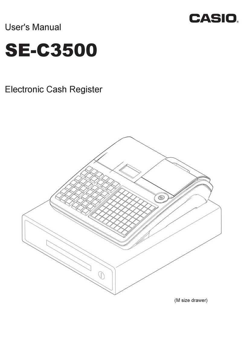
Casio
Casio TE-2000 User manual

Casio
Casio TE-2200 User manual

Casio
Casio TE-4000F Series User manual

Casio
Casio PCR-T273 User manual

Casio
Casio PCR-T2000 User manual

Casio
Casio SE-C2000 User manual

Casio
Casio SE-S400 User manual

Casio
Casio 210ER Assembly instructions

Casio
Casio TE8000 User manual

Casio
Casio CE-3700 User manual

Casio
Casio TE-100 User manual

Casio
Casio QT-2100 User manual

Casio
Casio TE-2200 User manual

Casio
Casio PCR-260B User manual
Casio
Casio SE-S300 User manual

Casio
Casio TE-2400 User manual