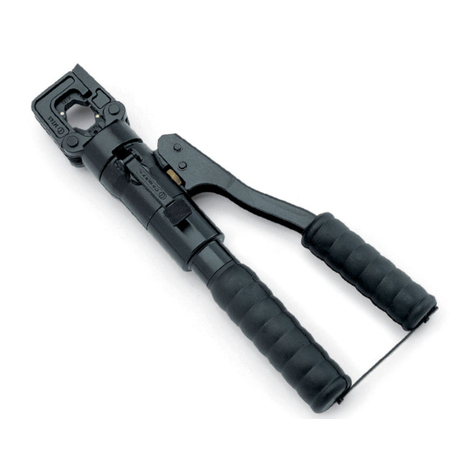
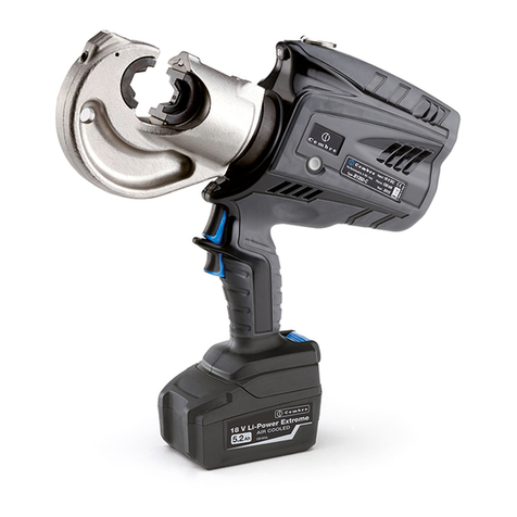
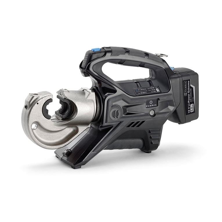
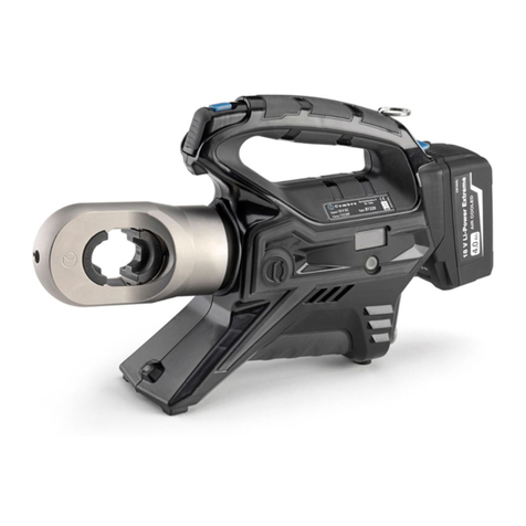
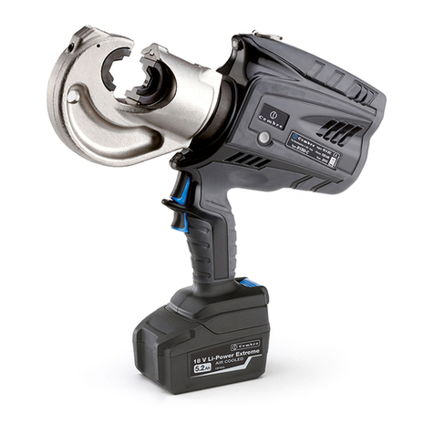
Cembre B35-50MD User manual

1
ENGLISH
FRANÇAIS
DEUTSCH
ESPAÑOL
ITALIANO
BATTERY OPERATED HYDRAULIC CRIMPING TOOL
OUTIL HYDRAULIQUE DE SERTISSAGE SUR BATTERIE
HYDRAULISCHES AKKU-PRESSWERKZEUG
HERRAMIENTA HIDRAULICA DE COMPRESIÓN A BATERíA
UTENSILE OLEODINAMICO DA COMPRESSIONE A BATTERIA
14 M 110
OPERATION AND MAINTENANCE MANUAL
NOTICE D'UTILISATION ET ENTRETIEN
BEDIENUNGSANLEITUNG
MANUAL DE USO Y MANTENIMIENTO
MANUALE D'USO E MANUTENZIONE
B35-50MD
B35-50MDA
B35-50MDE
B35-50MDT
ENGLIS
H
14
M
1
10
Certified Environmental
Management System Certified Occupational
Health & Safety
Management System
Certified Quality
Management System

2
B35-50MD
TYPE Made in Italy
FORCE 35 kN
– Before using the tool, carefully read the instructions in this manual.
– Avant d'utiliser cet outil, lire attentivement les instructions de cette notice.
– Vor Inbetriebnahme unbedingt die Bedienungsanleitung durchlesen.
– Antes de utilizar la herramienta, leer atentamente las instrucciones contenidas en este manual.
– Prima di utilizzare l'utensile, leggere attentamente le istruzioni contenute in questo manuale.
– When operating the tool, keep hands away from the danger zone.
– Au cours du sertissage, tenir les mains éloignées de la zone de travail.
– Während des Verpressens nicht mit den Händen in den Pressbereich gelangen.
– Durante su utilización, mantenga las manos fuera de la zona de peligro.
– Durante l'utilizzo, mantenere le mani fuori dalla zona di pericolo.
12
- Tool type
- Outil type
- Werkzeug Typ
- Herramienta tipo
- Tipo di utensile
- Force
- Force
- Kraft
- Fuerza
- Forza
12
– See page 34.
– Voir page 34.
– siehe Seite 34.
– Vease página 34.
– Vedere pagina 34.
WARNING LABELS - ETIQUETTES SIGNALETIQUES - WARNSCHILDER -
ETIQUETAS DE ATENCION - ETICHETTE D'AVVERTENZA
– Never throw batteries into re or water.
– Jamais jeter les batteries dans le feu ou dans l'eau.
– Werfen Sie Akkus nicht in das Feuer oder Wasser.
– Nunca tire las baterías al fuego o al agua.
– Mai gettare le batterie nel fuoco o in acqua.
– Always recycle the batteries.
– Recycler toujours les batteries.
– Verbrauchte Akkus stets dem Recycling zuführen.
– Reutilizar siempre las baterías.
– Riciclare sempre le batterie.
– Do not discard batteries into domestic refuse or waste disposal.
– Ne pas jeter de batteries dans une poubelle ou autre lieu non prévu à cet eet.
– Verbrauchte Akkus nicht der allgemeinen Abfallentsorgung zuführen.
– No tirar las baterías al cubo de basura o lugar paracido.
– Non buttare le batterie fuori uso nei cestini della spazzatura o luoghi simili.
Tool - Outil - Werkzeug - Herramienta - Utensile
Battery - Batterie - Akku - Batería - Batteria

3
2
4
OPERATING BUTTON
BOUTON D'ACTIONNEMENT
STARTKNOPF
PULSADOR DE ACCIONAMIENTO
PULSANTE DI AZIONAMENTO
9
PRESSURE RELEASE BUTTON
BOUTON DE DECOMPRESSION
DRUCKABLASSKNOPF
PULSADOR DE DESBLOQUEO PRESION
PULSANTE SBLOCCO PRESSIONE
3
BATTERY
BATTERIE
AKKU
BATERIA
BATTERIA
600
HEAD ROTATES 180°
TETE ROTATIVE A 180°
UM 180° DREHBARER KOPF
CABEZA GIRATORIA 180°
TESTA RUOTABILE DI 180°
24 - 27
LOWER AND UPPER DIE SUPPORT
PORTE MATRICE INFÉRIEUR ET SUPÉRIEUR
UNTERER UND OBERER PRESSEINSATZHALTER
SOPORTE MATRIZ INFERIOR Y SUPERIOR
SUPPORTO MATRICE INFERIORE E SUPERIORE
15
BATTERY RELEASE
DEBLOCAGE BATTERIE
AKKU ENTRIEGELUNG
DESBLOQUEO BATÉRIA
SBLOCCO BATTERIA
FIG. 1
BATTERY CONDITION DISPLAY
INDICATEUR DE CHARGE DE BATTERIE
AKKUANZEIGE
INDICADOR DE CARGA DE LA BATERIA
INDICATORE DI CARICA DELLA BATTERIA
BILD 1

4
ENGLISH
The part reference includes the following:
– Basic tool complete with battery.
– Spare battery.
– Battery charger (model depends on the tool version).
– Plastic carrying case.
BATTERY OPERATED HYDRAULIC CRIMPING TOOL
1. GENERAL CHARACTERISTICS
TOOL TYPE: B35-50MD
Acoustic Noise (Directive 2006/42/EC, annexe 1, point 1.7.4.2 letter u)
– The weighted continuous acoustic pressure level equivalent
A at the work place LpA is equal to .............................................................................................................. 64,9 dB (A)
– The maximum value of the weighted acoustic displacement
pressure C at the work place LpCPeak is equal to ........................................................................................ 99,7 dB (C)
– The acoustic power level emitted by the machine
LWA is equal to....................................................................................................................................................... 69,3 dB (A)
Risks due to vibration (Directive 2006/42/EC, annexe 1, point 2.2.1.1)
Tests carried out in compliance with the indications contained in UNI ENV 25349 and UNI EN 28662 part
1st Standards, and under operating conditions much more severe than those normally found, certify that
the weighted root mean square in frequency of the acceleration the upper limbs are exposed to for
each biodynamic reference axis is 0,527 m/sec2 max.
Application range:
Crimping force kN (sh ton):
Rated operating pressure bar (psi):
Dimensions
LxWxH
mm (inches):
Weight with battery kg (lbs):
Motor Volt DC:
Battery
type
CB1820L Volt / Ah:
Recommended oil:
Safety:
Operating temperature °C (°F):
Battery charger ASC30-36
Input Volt / Hz:
W:
suitable for installing electrical compression connectors
for conductors up to 150 mm2(300 MCM)
35 (4)
390 (5,600)
387 x 133 x 81 (15.2 x 5.2 x 3.2)
2,6 (5.7)
18
18 / 2.0 Li-Ion
AGIP ARNICA 22 or
ESSO INVAROL EP22
or equivalent
the tool is equipped with a maximum pressure valve
-15 to +50 (+5 to +122)
B35-50MDE B35-50MDT B35-50MDA
UE
27044000
UK
27045000
AUS/NZ
27047000
USA/CAN
27046000
220 - 240 / 50 - 60
85
115 / 60

5
ENGLISH
FIG. 2
24
58 59
27
25
2. INSTRUCTIONS FOR USE
2.1) Preparation (Ref. to Figs. 1, 2)
With the tool in the rest position, proceed as follows:
– Select the appropriate die set for the connector.
– Open the latch (25) and release the upper die holder (24).
– Insert one die into the upper die holder (24) and one die into the lower die support (27).
– Close the latch (25).
– Insert the conductor in the
connector.
– Position the connector be-
tween the dies and ensure
the correct location of the
crimp.
Ensure that the latch and
the upper die holder are
fully secured, otherwise
damage may occur
during tool operation.
2.2) Die advancement
– Grip the tool rmly and comfortably and press the operating button (4) to activate the
motor-pump and advance the lower die. To halt the advancement, release the operating
button (4) and the motor will cut out.
Make sure the dies are exactly positioned on the desired crimp point otherwise
re-open dies following instructions as per § 2.4 and reposition the connector.
2.3) Compression
– By keeping operating button (4) pressed, the motor continues to operate: the ram will
gradually move forward until the two dies touch.
It is recommended to keep operating until the maximum pressure valve is activated and
a "click" is heard.
– The motor will continue to operate after the maximum pressure relief valve has activated.
No further crimping force is applied, the oil is bypassed and returned to the reservoir.

6
ENGLISH
2.4) Release of dies
Press the pressure release button (9), the ram will retract and open the dies.
2.5) Head rotation
For ease of operation the tool head can rotate through 180°, allowing the operator to work in the
most comfortable position.
Warning: do not attempt to rotate the head when the hydraulic circuit is pressurised.
2.6) Replacement of dies
To replace the dies, open the head and extract them from their seats.
2.7) Battery status (Ref. to Fig. 3)
The battery is equipped with LED indicators that indicate the remaining battery life at any time by
pressing the adjacent button (P).
4 LEDs illuminated: Fully charged
2 LEDs illuminated: 50 % capacity
1 LED ashing: Minimum charge, replace the battery
2.8) Insertion/replacement of battery
To replace the battery, remove it by pressing the release button (15) (Ref. to Fig.5 page 24), then
insert the new battery, sliding it into the guides until it locks.
3. WARNING
Before starting work on electrical equipment, please ensure that either there are no live parts in
the immediate working area or that precautions are taken for working near live parts in accordance
with EN50110-1.
DONOT USE THIS TOOL ON OR NEAR ENERGIZED CONDUCTORS WITHOUT PROPER
PERSONAL PROTECTIVE EQUIPMENT. FAILURE TO OBSERVE THIS WARNING COULD
RESULT IN SEVERE INJURY OR DEATH.
THE TOOL IS UNSUITABLE FOR CONTINUOUS USE AND SHOULD BE ALLOWED TO
COOL DOWN FOLLOWING UNINTERRUPTED, SUCCESSIVE CRIMPING OPERATIONS; FOR
INSTANCE, HAVING EXHAUSTED AFULLY CHARGED BATTERY IN ONE SESSION, DELAY
BATTERY REPLACEMENT FOR AFEW MINUTES.
OBSERVE RECOMMENDED REST PERIODS ALSO WHEN USING AN EXTERNAL POWER
SUPPLY.
P
ROTECT THE TOOL FROM RAIN AND MOISTURE. WATER WILL DAMAGE THE TOOL
AND BATTERY. ELECTRO-HYDRAULIC TOOLS SHOULD NOT BE OPERATED IN POURING
RAIN OR UNDER WATER.
2
FIG. 3
P

7
ENGLISH
3.1) Using the battery charger
Carefully follow the instructions in the battery charger manual.
4. MAINTENANCE
The tool is robust, completely sealed, and requires very little daily maintenance.
Compliance with the following points, should help to maintain the optimum performance of the
tool:
4.1) Thorough cleaning
Dust, sand and dirt are a danger for any hydraulic device.
Every day, after use, the tool must be wiped with a clean cloth taking care to remove any residue,
especially close to moveable parts.
4.2) Storage (Ref. to Fig, 4)
When not in use, the tool should be stored and transported in the plastic case to prevent damage.
The case is suitable for storing the tool, the accessories and die sets.
Plastic case: VAL P22, size 465x315x135 mm (18.3x12.4x5.3 in.) weighs 1,5 kg (3.3 lbs).
5. RETURN TO Cembre FOR OVERHAUL
In the case of a breakdown contact our Area Agent who will advise you on the problem and give
you the necessary instructions on how to dispatch the tool to our nearest service Centre; if possible,
attach a copy of theTest Certicate supplied by Cembretogether with the tool or, if no other refer-
ences are available, indicate the approximate purchase date and the tool serial number.

8
FRANÇAIS
OUTIL HYDRAULIQUE DE SERTISSAGE SUR BATTERIE
1. CARACTERISTIQUES GENERALES
L'ensemble comprend:
– Outil de base avec batterie.
– Batterie de rechange.
– Chargeur de batterie (diérent en fonction de la version de l'outil).
– Coret de rangement.
OUTIL TYPE:
B35-50MD
Pression sonore aérienne (Directive 2006/42/CE, annexe 1, point 1.7.4.2, lettre u)
– Le niveau de pression sonore continue équivalente
pondérée A sur le poste de travail LpA est ................................................................................................. 64,9 dB (A)
– Le niveau de pression sonore instantanée pondéré
C sur le poste de travail LpCPeak est ................................................................................................................. 99,7 dB (C)
– Le niveau de puissance acoustique dégagée par la
machine LWA est ................................................................................................................................................... 69,3 dB (A)
Risques dérivés des vibrations (Directive 2006/42/CE, annexe 1, point 2.2.1.1)
Des relevés réalisés suivant les indications des Normes UNI ENV 25349 et UNI EN 28662 partie 1a, dans
des conditions de service largement représentatives des conditions d'emploi normales témoignent que la
valeurquadratiquemoyennepondéréeenfréquencedel'accélérationàlaquellesontexposéslesmembres
supérieurs pour chaque axe biodynamique de référence est de 0,527 m/sec2maxi.
Domaine d'application:
Force de sertissage kN (sh ton):
Pression nominale bar (psi):
Dimensions
LxLxH
mm (inches):
Poids avec batterie kg (lbs):
Moteur Volt DC:
Batterie
type
CB1820L Volt / Ah:
Huile recommandée:
Sécurité:
Température de fonctionnement °C (°F):
Chargeur de batterie ASC30-36
Alimentation Volt / Hz:
W:
conçu pour le sertissage des connecteurs électriques
pour conducteurs jusqu' à 150 mm2(300 MCM)
35 (4)
390 (5,600)
387 x 133 x 81 (15.2 x 5.2 x 3.2)
2,6 (5.7)
18
18 / 2.0 Li-Ion
AGIP ARNICA 22 ou
ESSO INVAROL EP22
ou équivalents
l’outil est équipé d'une valve de surpression
-15 à +50 (+5 à +122)
B35-50MDE B35-50MDT B35-50MDA
UE
27044000
UK
27045000
AUS/NZ
27047000
USA/CAN
27046000
220 - 240 / 50 - 60
85
115 / 60

9
FRANÇAIS
FIG. 2
24
58 59
27
25
2. INSTRUCTIONS D'UTILISATION
2.1) Mise en service (Voir Fig. 1, 2)
Avec l’outil en position repos, procéder de la façon suivante:
– Choisir le couple de matrices approprié pour le type de connexion à réaliser; pour cela,
consulter le catalogue.
– Ouvrir la tête de l'outil en écartant le levier (25), libérant ainsi le porte matrice supérieur
(24) qui s'écartera complètement grâce au ressort.
– Insérer les matrices dans les porte matrices supérieurs (24) et inférieurs (27).
– Refermer la tête.
– Insérer le conducteur dans
le connecteur.
– Positionner ce dernier entre
les deux matrices en alig-
gnant la zone àsertir avec
l'empreinte des matrices.
Avant de poursuivre les
opérations, vérifier que
la tête soit parfaitement
fermée.
2.2) Avance des matrices
– Empoigner fort l'outil et appuyer sur le bouton de commande (4) pour mettre en marche le
groupe moteur pompe; les matrices commencent alors à se rapprocher du connecteur.
Le bouton de commande (4) relâchée, le moteur et l'avance des matrices cessent
immédiatement.
S'assurer que les matrices sont bien positionnées sur la zone à sertir, sinon des-
serer les en suivant les instructions du § 2.4 et repositionner le connecteur.
2.3) Sertissage
– En maintenant pressé le bouton de commande (4), on maintient la rotation du moteur;
le piston avance progressivement jusqu'à ce que les matrices arrivent en butée l'une
contre l'autre.
Nous recommandons en tout cas d'actionner le moteur jusqu'au déclenchement de la
valve de surpression que l'on entendra distinctement.
– Après ce déclenchement, même si l'on maintient le moteur actionné, on n'obtiendra
aucune poussée sur les matrices car l'huile sera déviée directement au réservoir.

10
FRANÇAIS
2.4) Réouverture des matrices
Appuyer à fond sur le bouton de décompression (9) pour provoquer l'ouverture des matrices.
2.5) Rotation de la tête
La tête de l'outil pivote de 180° par rapport au corps, permettant à l'utilisateur de travailler
dans la meilleure position.
Attention: ne pas forcer la rotation de la tête, lorsque le circuit hydraulique est sous pression.
2.6) Remplacement des matrices
Pour le remplacement des matrices, ouvrir la tête et les enlever de leurs sièges.
2.7) Autonomie de la batterie (Voir Fig. 3)
La batterie est équipée d'indicateurs à LED qui permettent de contrôler, à tout moment, son auto-
nomie résiduelle en appuyant sur la touche (P).
4 led allumées: autonomie maximale
2 led allumées: autonomie à 50 %
1 led clignotante: autonomie minimale, remplacer la batterie.
2.8) Introduction/replacement de la batterie
Pour remplacer la batterie, la retirer en appuyant sur le mécanisme de déblocage (15) (Voir Fig. 5,
page 24), puis introduire la nouvelle batterie en la faisant coulisser sur les guides jusqu'au blocage
complet.
3. PRECAUTIONS
Avant d’entreprendre des travaux sur des équipements électriques, veuillez vous assurer qu’aucun
élément aux abords de la zone de travail n’est sous tension. Dans le cas contraire, veuillez prendre
les précautions nécessaires pour opérer à proximité d’éléments sous tension, en conformité avec
la norme EN50110-1.
NEPAS UTILISER CET OUTIL SUR OU ACOTE DE CONDUCTEURS SOUS TENSION, SANS
PROTECTION INDIVIDUELLE ADEQUATE. LA NON OBSERVATION DE CETTE PRECAUTION
PEUT PROVOQUER DES LESIONS GRAVES OU MORTELLES.
L’OUTIL N’EST PAS CONÇU POUR UNE UTILISATION EN CONTINU; APRÈS AVOIR EF-
FECTUÉ UNE QUANTITÉ DE SERTISSAGES CONSÉCUTIFS ÀPARTIR D’UNE BATTERIE
COMPLÈTEMENT CHARGÉE, AU MOMENT DU REMPLACEMENT DE LA BATTERIE, NOUS
SUGGÉRONS D’OBSERVER UNE PÉRIODE D’ARRÊT POUR PERMETTRE LE REFROI-
DISSEMENT DE L’OUTIL.
L
AISSER REPOSER L’OUTIL MÊME EN CAS D’UTILISATION D’UN ALIMENTATEUR DE RÉSEAU.
PROTÉGER L’OUTIL DE LA PLUIE ET DE L’HUMIDITÉ. L’EAU POURRAIT ENDOMMAGER
L’OUTIL ET LA BATTERIE LES OUTILS HYDRO-ELECTRIQUE NE DEVRAIENT PAS ÊTRE
UTILISÉS SOUS LA PLUIEET SOUS L’EAU.
FIG. 3
2P

11
FRANÇAIS
3.1) Utilisation du chargeur de batterie
Suivre attentivement les instructions indiquées sur le manuel.
4. ENTRETIEN
Cet outil est robuste, complètement scellé et ne nécessite aucune préoccupation ou entretien
particulier. Les recommandations qui suivent sont néanmoins souhaitables pour assurer une lon-
gévité optimum:
4.1) Nettoyage élémentaire
Veiller à protéger l'outil de la poussière, du sable et de la boue qui sont un danger à tout système
hydraulique. Chaque jour après utilisation, l'outil doit être nettoyé à l'aide d'un chion propre, tout
particulièrement aux endroits de pièces mobiles.
4.2) Rangement (Voir Fig. 4)
Au repos, pour protéger l'outil des coups accidentels et de la poussière, il convient de le ranger dans
le coret. Ce coret (type VAL P22) a comme dimensions: 465x315x135 mm (18.3x12.4x5.3 in.) et
un poids de 1,5 kg (3,3 lbs), est adapté pour contenir l'outil, ses accessoires et les matrices.
5. ENVOI EN REVISION A Cembre
En cas de dysfonctionnement de l'appareil, merci de vous adresser à notre Agent Régional qui
vous conseillera et le cas échéant vous donnera les instructions nécessaires pour envoyer l'outil à
notre Centre de Service le plus proche. Dans ce cas, joindre une copie du Certicat d'Essai livré par
Cembreavec l'outil ou, à défaut d'autres éléments de référence, indiquer la date d'achat approxi-
mative et numéro de série.

12
DEUTSCH
HYDRAULISCHES AKKU-PRESSWERKZEUG
1. ALLGEMEINE EIGENSCHAFTEN
Zum Lieferumfang unter dieser Bezeichnung gehören folgende Teile:
– Basisausführung inkl. Akku
– Ersatzakku
– Ladegerät (entsprechend der Länderkonguration)
– Kunststokoer
WERKZEUG TYP:
B35-50MD
Lärmschutzbestimmung (Richtlinie 2006/42/EG, Anhang 1, Nummer 1.7.4.2, Buchstabe u)
– Der konstante Lärmpegel entsprechend
Gewichtung A am Arbeitsplatz LpA entspricht ......................................................................................... 64,9 dB (A)
– Der höchste Lärmpegel entsprechend
Gewichtung C am Arbeitsplatz LpCPeak entspricht .................................................................................... 99,7 dB (C)
– Die Lärmbelastung des Geräts
L
WA entspricht ....................................................................................................................................................... 69,3 dB (A)
Risiken aufgrund von Vibrationen (
Richtlinie 2006/42/EG
, Anhang 1,
Nummer
2.2.1.1)
Messungen entsprechend der Normen UNI ENV 25349 und UNI EN 28662 Teil 1, unter repräsentativen
Bedingungenhabengezeigt,daßderdurchschnittlicheMeßwertandenoberenTeilen,diedenVibrationen
ausgesetzt sind, an den jeweiligen Achsen ist den Wert höchstens von 0,527 m/sek2.
Anwendungsbereich:
Preßkraft kN (sh ton):
Arbeitsdruck bar (psi):
Abmessungen
LxBxH
mm (inches):
Gewicht inkl. Akku kg (lbs):
Motor Volt DC:
Akku
Typ
CB1820L Volt / Ah:
Empfohlenes Öl:
Sicherheit:
Betriebstemperatur °C (°F):
Akkuladeger
ät
ASC30-36
Eingangspannung Volt / Hz:
W:
Geeignet zum Verpressen von Verbindern und Kabelschuhen
bis zu einem Querschnitt von max.
150 mm2(300 MCM)
35 (4)
390 (5,600)
387 x 133 x 81 (15.2 x 5.2 x 3.2)
2,6 (5.7)
18
18 / 2.0 Li-Ion
AGIP ARNICA 22 oder ESSO INVAROL EP22 oder ähnliches
Das Werkzeug ist mit einem Überdruckventil ausgestattet
-15 bis +50 (+5 bis +122)
B35-50MDE B35-50MDT B35-50MDA
UE
27044000
UK
27045000
AUS/NZ
27047000
USA/CAN
27046000
220 - 240 / 50 - 60
85
115 / 60

13
DEUTSCH
24
58 59
27
25
BILD 2
2. BEDIENUNGSHINWEISE
2.1) Vorbereitung (siehe Bild 1, 2)
Wenn das Werkzeug in Ruhestellung ist, sind folgende Schritte notwendig:
– Passenden Presseinsatz auswählen.
– Öffnen Sie den Kopf der Akkupresse am Haken (25) und der obere Presseinsatzhalter
(24) kann weit geönet werden.
– Setzen Sie die Presseinsätze in die vorgesehene Halterung ein: den oberen Presseinsatz in
den Presseinsatzhalter (24) bis er in die Feder einrastet, sowie den unteren Presseinsatz
ebenfalls in den Presseinsatzhalter (27) einrasten.
– Schließen Sie den Presskopf.
– Den zu verpressenden Lei-
ter in den Verbinder oder
Kabelschuh einlegen.
– Positionieren Sie den Ver-
binder oder Kabelschuh an
der vorgeschriebenen Posi-
tion.
Vor Inbetriebnahme der
Akkupresse muss der
Kopf vollständig ge-
schlossen sein, sonst
kann es zu Beschädigun-
gen kommen.
2.2) Positionierung
– Das Werkzeug fest in die Hand nehmen und durch Drücken des Startknopfes (4) be-
ginnen Motor und Pumpe zu arbeiten und die Preßeinsätze nähern sich dem Verbinder
oder Kabelschuh. Sobald der Startknopf (4) wieder losgelassen wird, halten Motor und
Kolben sofort an.
Die Presseinsätze müssen an der korrekten Position vom Kabelschuh oder
Verbinder befinden. Sollte diese nicht korrekt sein, muss das Werkzeug
entsprechend Punkt 2.4 geöffnet werden und es kann neu positioniert werden.
2.3) Verpressung
– Wird der Startknopf (4) weiter gedrückt, fahren die Presseinsätze langsam aufeinander
zu und die Verpressung wird durchgeführt.
Wir empfehlen, den Motor solange laufen zu lassen, bis das Überdruckventil mit einem
“Klick”anspricht.
– Das Öl läuft dann in denVorratsbehälter und ein weiterer Druckaufbau ist somit ausgeschlossen.

14
DEUTSCH
2.4) Önen der Presseinsätze
Drücken Sie kräftig den Druckablassknopf (9), die Presseinsätze geben den Verbinder frei.
2.5) Drehbewegung des Kopfes
Das Werkzeug ist mit einem Kopf ausgerüstet, der um 180° drehbar ist und somit ein komfortables
Arbeiten ermöglicht.
Der Kopf sollte keinesfalls in eine andere Position gedreht werden, während die Akkupresse unter
Druck steht.
2.6) Presseinsätze wechseln
Um die zu wechseln, den Presskopf önen und Presseinsätze entfernen.
2.7) Akkuladung (Siehe Bild 3)
Die Akku ist mit LED-Anzeigen ausgestattet, die jederzeit über die verbleibende Akkulaufzeit Aus-
kunft gibt, indem man auf die Taste (P) drückt.
4 LED eingeschaltet: Maximale Ladung
2 LED eingeschaltet: Ladung zu 50 %
1 LED blinkend: Minimale Ladung, Akku austauschen bzw. auaden
2.8) Akku Einsetzen/Auswechseln
Drücken Sie für den Akkuaustausch auf die Entriegelung (15) (siehe Bild 5, Seite 24) und führen Sie
den neuen Akku bis zum Einratsen ein.
3. HINWEISE
VorBeginnderArbeitenanelektrischenAnlagenistsicherzustellen,dasssichkeinespannungsführen-
den Teile in unmittelbarer Nähe des Arbeitsbereiches benden. Ansonsten muss durch geeignete
Maßnahmen entsprechend der EN 50110-1 der Arbeitsbereich abgesichert werden.
DIESES WERKZEUG NICHT AN ODER IN DER NÄHE VON STROMFÜHRENDEN LEITUNGEN
VERWENDEN, OHNE AUSREICHENDE SCHUTZMASSNAHMEN!
EINE NICHTBEACHTUNG VON DEN SCHUTZMASSNAHMEN KANN ZU VERLETZUNGEN
ODER ZUM TODE FÜHREN.
DIE AKKUWERKZEUGE SIND NICHT FÜR EINEN DAUEREINSATZ GEEIGNET. WENN
EIN VOLL GELADENER AKKU DURCH HINTEREINANDER AUSGEFÜHRTE VERPRES-
SUNGEN GETAUSCHT WERDEN MUSS, EMPFEHLEN WIR VOR DEM AKKUWECHSEL
DAS WERKZEUG EINE ANGEMESSENE ZEIT ABKÜHLEN ZU LASSEN.
DAS SCHALTNETZTEIL IST NICHT FÜR DEN DAUERBETRIEB GEEIGNET!
DAS WERKZEUG VOR REGEN UND FEUCHTIGKEIT SCHÜTZEN. WASSER KÖNNTE
DAS WERKZEUG UND DEN AKKU BESCHÄDIGEN. ELEKTROHYDRAULISCHE WERK-
ZEUGE SOLLTEN NICHT IM REGEN ODER UNTER FLIESSENDEM WASSER EINGESETZT
WERDEN.
2P
BILD 3

15
DEUTSCH
3.1) Verwendung des Ladegerätes
Die in der Bedienungsanleitung gegebenen Hinweise sind zu beachten.
4. WARTUNG
Das Werkzeug ist robust und benötigt keine spezielle Pege oder Instandhaltung.
Zur Erhaltung der Garantieansprüche beachten Sie folgende Hinweise:
4.1) Pege
Dieses hydraulische Werkzeug sollte vor starker Verschmutzung geschützt werden, da dies für ein
hydraulisches System gefährlich ist. Jeden Tag nach der Arbeit sollte dasWerkzeug mit einemTuch
von Schmutz und Staub gereinigt werden, besonders die beweglichen Teile.
4.2) Lagerung (siehe Bild 4)
Wenn das Werkzeug nicht benötigt wird, sollte es in der Kunststokassette gelagert werden und
ist somit gegen Beschädigungen wie Stoß und Staub geschützt.
DieKunststokassetteTypVALP22hatfolgendeAbmessungen:465x315x135mm(18.3x12.4x5.3in.)
undeinGewichtvon1,5kg(3,3lbs),geeignetzumLagernvonWerkzeug,ZubehörundPresseinsätzen.
5. EINSCHICKEN AN Cembre ZUR ÜBERPRÜFUNG
Sollten an dem Gerät Fehler auftreten, wenden Sie sich bitte an unsere Gebietsvertretung, die
Sie gerne beraten und Ihnen alle nötigen Informationen zum Einsenden des Gerätes an unseren
Hauptsitz geben wird. Wenn vorhanden, legen Sie dem Gerät bitte eine Kopie des von Cembre
mitgelieferten Zertikates bei. Bei fehlenden Informationen geben Sie bitte an, wann Sie das Gerät
erworben haben.

16
ESPAÑOL
HERRAMIENTA HIDRAULICA DE COMPRESIÓN A BATERíA
1. CARACTERíSTICAS GENERALES
La sigla identica el conjunto formado por:
– Herramienta base con batería.
– Batería de reserva.
– Cargador de batería (diferente según el modelo de la herramienta).
– Caja de almacenamiento.
HERRAMIENTA TIPO:
B35-50MD
Nivel sonoro aéreo (Directiva 2006/42/CE, anexo 1, punto 1.7.4.2, letra u)
– El nivel de presión acústica contínua equivalente
ponderado A en el puesto de trabajo LpA es de ...................................................................................... 64,9 dB (A)
– El nivel máximo de la presión acústica instantánea
ponderada C en el puesto de trabajo LpCPeak es de ................................................................................. 99,7 dB (C)
– El nivel de potencia acústica emitida por la máquina
LWA es de ................................................................................................................................................................ 69,3 dB (A)
Riesgos debidos a las vibraciones (Directiva
2006/42/CE
,
anexo 1, punto
2.2.1.1)
Medidas realizadas según las indicaciones de las Normas UNI ENV 25349 y UNI EN 28662 parte 1a, en
condiciones de utilización ampliamente representativas respecto a las que se encuentran normalmente,
atestan que el valor cuadrático medio ponderado en frecuencia, de la aceleración a la que están expuestos
los miembros superiores para cada eje biodinámico de referencia, es al máximo de 0,527 m/sec2.
Campo de aplicación:
Fuerza desarrollada kN (sh ton):
Presión nominal de trabajo bar (psi):
Dimensiones
LxAxA
mm (inches):
Peso con batería kg (lbs):
Motor Volt DC:
Batería
tipo
CB1820L Volt / Ah:
Aceite recomendado:
Seguridad:
Temperatura de funcionamiento °C (°F):
Cargador de batería ASC30-36
Alimentación Volt / Hz:
W:
para la instalación de conectores eléctricos por compresión
para conductores hasta
150 mm2(300 MCM)
35 (4)
390 (5,600)
387 x 133 x 81 (15.2 x 5.2 x 3.2)
2,6 (5.7)
18
18 / 2.0 Li-Ion
AGIP ARNICA 22 o
ESSO INVAROL EP22 o equivalentes
la herramienta está provista de válvula de sobrepresión
-15 a +50 (+5 a +122)
B35-50MDE B35-50MDT B35-50MDA
UE
27044000
UK
27045000
AUS/NZ
27047000
USA/CAN
27046000
220 - 240 / 50 - 60
85
115 / 60

17
ESPAÑOL
FIG. 2
24
58 59
27
25
2. INSTRUCCIONES DE USO
2.1) Preparación (Ref. a Fig. 1, 2)
Con la herramienta en posición de reposo, opere como sigue:
Seleccionar las matrices adecuadas para la conexión a efectuar.
– Abrir la cabeza de la herramienta moviendo hacia el exterior el gancho (25) hasta que
se suelte el soporte de matriz (24).
– Insertar las matrices en sus respectivos asientos: la superior en el soporte de matriz
(24) hasta que se bloquee con la bola (58); la inferior en el soporte empuja-matrices
(27) hasta que se bloquee con los muelles (59).
– Volver a cerrar la cabeza.
– Introduzca el conductor
en el conector.
– Coloque este último
entre las dos matrices,
alineando la zona a com-
primir con la marca de las
matrices.
Antes de proceder con
las operaciones si-
guientes, comprobar
que la cabeza está per-
fectamente cerrada.
2.2) Aproximación de las matrices
– Empuñar rmemente la herramienta y apretar el pulsador de accionamiento (4): se pone
en marcha el grupo motor-bomba y las matrices empiezan a acercarse al conector;
soltando el pulsador (4) se detienen inmediatamente tanto el motor como el movimiento
de las matrices.
Asegúrese de que las matrices se encuentran exactamente en correspondencia
con la zona a comprimir; en caso contrario, vuélvala a abrir, siguiendo las ins-
trucciones del punto 2.4 y vuelva a colocar el conector.
2.3) Compresión
– Manteniendo apretado el pulsador de accionamiento (4), el pistón avanzará progresi-
vamente hasta llevar las matrices a chocarse entre ellas.
Aconsejamos de todas maneras accionar el motor hasta que la válvula de sobrepresión
intervenga, de esta válvula se notará claramente el arranque.
– Después de la intervención de la válvula de sobrepresión, incluso manteniendo accionado
el motor, puesto que el aceite es desviado directamente al depósito, no se obtiene
ningún empuje sobre las matrices.

18
ESPAÑOL
2.4) Desbloqueo de las matrices
Apretando a fondo el pulsador de desbloqueo de la presión (9) se obtendrá el retorno del pistón
con la consiguiente apertura de las matrices.
2.5) Rotación de la cabeza
La cabeza de la herramienta puede rotar 180° respecto al cuerpo, permitiendo al operario realizar
el trabajo en la posición más adecuada.
Atención: no fuerce la cabeza, intentando rotarla, mientras el circuito hidráulico esté presurizado.
2.6) Cambio de las matrices
Para la sustitución de las matrices, abrir la cabeza y extraer las matrices.
2.7) Autonomía de la batería (Ref. a Fig. 3)
Labateríaestá provistade indicadoresdeledque permitensaberla autonomíarestanteen cualquier
momento pulsando el botón (P).
4 led encendidos: autonomía máxima
2 led encendidos: autonomía al 50 %
1 led parpadeante: autonomía mínima, reemplazar la batería
2.8) Inserción/sustitución de la batería
Para sustituir la batería, retírela pulsando el desbloqueo (15) (Ref. a Fig. 5, pag. 24) y luego inserte
la nueva batería deslizándola por las guías hasta su tope.
3. ADVERTENCIAS
Antes de empezar obras sobre elementos eléctricos, cerciorarse que no hay partes en tensión en
las proximidades de la zona de trabajo; en caso contrario adoptar las precauciones necesarias para
trabajar cerca de elementos en tensión en conformidad con la normativa EN50110 -1.
NOUSAR ESTA HERRAMIENTA SOBRE OCERCA DE CONDUCTORES EN TENSIÓN, SIN
SISTEMAS DE PROTECCIÓN INDIVIDUAL ADECUADAS.
LANO OBSERVACION DE ESTA MEDIDA PODRÍA CAUSAR LESIONES GRAVES OMORTALES.
EJECUTADO EL NUMERO DE OPERACIONES MÁXIMO PERMITIDO POR UNA BATERÍA,
ALA HORA DE CAMBIARLA, ACONSEJAMOS UN OPORTUNO PERÍODO DE PAUSA PARA
PERMITIR EL ENFRIAMIENTO DEL LA HERRAMIENTA.
TAMBIÉN UTILIZANDO ALIMENTADORES DE RED OBSERVAR OPORTUNOS PERÍODOS
DE PAUSA.
PROTEGER LA HERRAMIENTA DE LA LLUVIA YLA HUMEDAD. ELAGUA PODRÍA
DAÑAR LA HERRAMIENTA YLA BATERÍA. LAS HERRAMIENTAS ELECTROHIDRÁULICAS
NO DEBERÍAN FUNCIONAR BAJO LA LLUVIA ODEBAJO DEL AGUA.
FIG. 3
2P

19
ESPAÑOL
3.1) Utilización del cargador de batería
Seguir atentamente las instrucciones detalladas en el manual correspondiente.
4. MANTENIMIENTO
Esta herramienta es robusta, completamente precintada y no requiere cuidados especiales para
obtener un funcionamiento correcto, bastará tener algunas precauciones sencillas:
4.1) Limpieza adecuada
Tenga presente que el polvo, la arena y la suciedad en general, representan un peligro para toda
herramienta hidráulica. Tras cada día de uso, se debe limpiar la herramienta con un trapo limpio,
teniendo cuidado de eliminar la suciedad depositada, especialmente junto a las partes móviles.
4.2) Almacenamiento (Ref. a Fig. 4)
Para proteger la herramienta de golpes accidentales y del polvo cuando no se va a utilizar, es con-
veniente guardarla cerrada en su estuche de plástico de cierre hermético.
Dicho estuche tipo VAL P22 de dimensiones 465x315x135 mm (18.3x12.4x5.3 in.), pesa 1,5 kg (3.3
lbs). Es apropiado para almacenar la herramienta, los accesorios y las matrices.
5. DEVOLUCION A Cembre PARA REVISIONES
En caso de fallo de la herramienta, contactar con nuestro Agente de Zona quien les aconsejará y
eventualmente les facilitará las instrucciones necesarias para remitir la herramienta a nuestro centro
de servicio más cercano. En tal caso, adjuntar a ser posible una copia del Certicado de Ensayo en-
tregado en su día por Cembrecon la herramienta o a falta de otro elemento de referencia indicar
la fecha de compra aproximada y el número de serie.

20
ITALIANO
La fornitura comprende:
– Utensile base completo di batteria.
– Batteria di riserva.
– Caricabatterie (dierente in base alla versione dell'utensile).
– Valigetta di contenimento.
UTENSILE OLEODINAMICO DA COMPRESSIONE A BATTERIA
1. CARATTERISTICHE GENERALI
UTENSILE TIPO:
B35-50MD
Rumore Aereo (Direttiva 2006/42/CE, allegato 1, punto 1.7.4.2, lettera u)
– Il livello di pressione acustica continuo equivalente
ponderato A nel posto di lavoro LpA è pari a ............................................................................................. 64,9 dB (A)
– Il valore massimo della pressione acustica istantanea
ponderata C nel posto di lavoro LpCPeak è pari a ........................................................................................ 99,7 dB (C)
– Il livello di potenza acustica emessa dalla macchina
LWA è pari a.............................................................................................................................................................. 69,3 dB (A)
Rischi dovuti alle vibrazioni (Direttiva 2006/42/CE, allegato 1, punto 2.2.1.1)
Rilievi condotti, secondo le indicazioni delle Norme UNI ENV 25349 e UNI EN 28662 parte 1a, in condizioni
di utilizzo ampiamente rappresentative rispetto a quelle normalmente riscontrabili, attestano che il valore
quadratico medio ponderato, in frequenza, dell'accelerazione cui sono esposte le membra superiori, per
ciascuno degli assi biodinamici di riferimento, è al massimo di 0,527 m/sec2.
Campo di applicazione:
Forza sviluppata kN (sh ton):
Press. nom. di esercizio bar (psi):
Dimensioni
LxLxA
mm (inches):
Peso con batteria kg (lbs):
Motore Volt DC:
Batteria
tipo
CB1820L Volt / Ah:
Olio consigliato:
Sicurezza:
Temperatura di funzionamento °C (°F):
Caricabatteria ASC30-36
Alimentazione Volt / Hz:
W:
adatto all'installazione di connettori elettrici a compres-
sione per conduttori in genere no a 150 mm2(300 MCM)
35 (4)
390 (5,600)
387 x 133 x 81 (15.2 x 5.2 x 3.2)
2,6 (5.7)
18
18 / 2.0 Li-Ion
AGIP ARNICA 22 o
ESSO INVAROL EP22
o equivalenti
l’utensile è munito di valvola di massima pressione
-15 a +50 (+5 a +122)
B35-50MDE B35-50MDT B35-50MDA
UE
27044000
UK
27045000
AUS/NZ
27047000
USA/CAN
27046000
220 - 240 / 50 - 60
85
115 / 60
This manual suits for next models
3
Table of contents
Languages:
Other Cembre Crimping Tools manuals

Cembre
Cembre HT60C User manual

Cembre
Cembre HT45 User manual

Cembre
Cembre B600C User manual

Cembre
Cembre B1320 User manual

Cembre
Cembre B1350-CA User manual

Cembre
Cembre Crimpstar HP3 User manual

Cembre
Cembre HT61 User manual

Cembre
Cembre B54-YD6 User manual

Cembre
Cembre RH-FC48N User manual

Cembre
Cembre B500A User manual

Cembre
Cembre RHT160 User manual

Cembre
Cembre B1350-C User manual

Cembre
Cembre B54N-YD6 User manual

Cembre
Cembre B15MA User manual

Cembre
Cembre B-TC550 User manual

Cembre
Cembre B1500A User manual

Cembre
Cembre RHC131 User manual
Cembre
Cembre ht51 User manual
Cembre
Cembre B540ND-BVA User manual

Cembre
Cembre B540ND-BVE User manual