--- J~
GENERAL
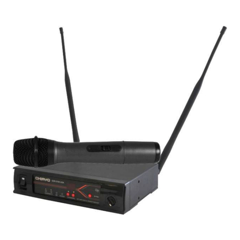
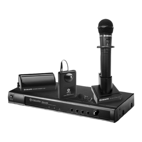
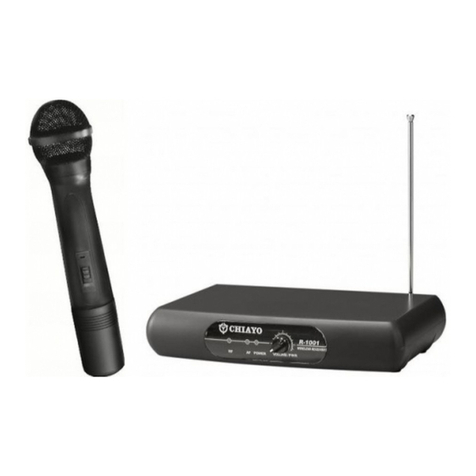
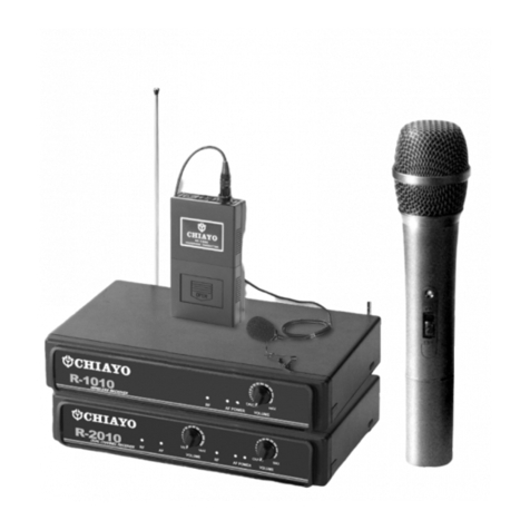
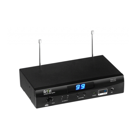
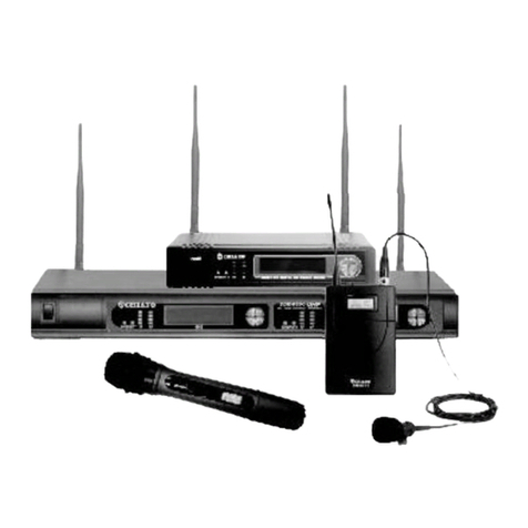
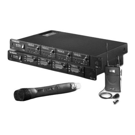
R-1001/ R-2001 is a VHF high-band non-diversity system with quartz controlled
fixedfrequency design. The receiver must be combined with Chiayo's Q- and M-
series of wireless microphone.
COMPOSITION
1. MAINFRAME:R-1001/ R-2001
2.ACCESSORIES:1)ACadapter 2)antennaX 1(R-1001)/antenna X2(R-2001)
3)Outputcable / PHONE 4)Operatingmanual
COMBINATION
1. MATCHINGWIRELESS MICROPHONE:Q- and M-series such as Q-1001 &
M-1001
CONTROLS AND FUNCTIONS
FRONT PANEL
REAR PANEL
s
CONTROLS AND FUNCTIONS
I.POWER SWITCH AND VOLUME CONTROL
Turn the knob clockwise until it clicks to switch on the power. Further turning will incre-
ase the volume.
<..POWER ON INDICATOR
When power is switched on ' the power on LED will light up.
3 .RF SIGNAL INDICATOR
Indicates RF signal received. As soon as signal is emitted from the microphone' the
LED of the indicator will light up.
4.AF SIGNAL INDICATOR
Indicates the audio signal. When sound is applied to microphone' LED will light up.
5.ANTENNA INPUT JACK(R-1001)
For direct mounting of antenna or antenna extension cable.
6.UNBALANCED AUDIO OUTPUT JACK
7.SO CONTROL
muting level can be adjusted by SO control.
8 DC POWER SUPPLY INPUT SOCKET
A 12-15V external DC power supply or an AC adapter could be connected to this socket
while the negative is grounded.
9.CH2 VOLUME CONTROL(R-2001)
to.ANTENNA 1 INPUT JACK (R-2001)
11.ANTENNA 2 INPUT JACK (R-2001)
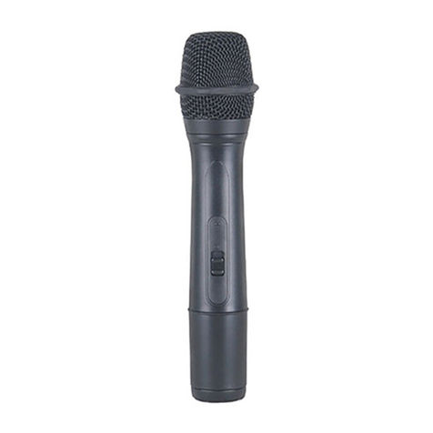
HAND-HELD Microphone (Q-1001)
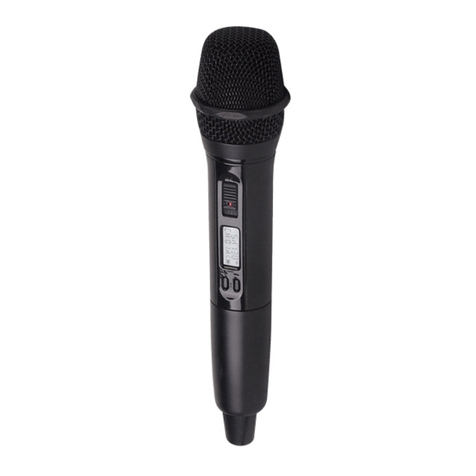
1.The microphone is shown in Fig 1.
Windscreen and capsule setBattery status indicator
~Fig. 1.
Transmitter electronics Battery compartment
.: Wireless Microphone
2.To access to the battery compartment, loosen the battery pack in counter clockwise
direction, as shown in Fig. 2.
Fig. 2.
3. Insert one piece of 9V battery with correct polarity, as shown in Fig. 3. Before
inserting the battery, make sure that the power switch is switched off.
Fig. 3
4. After putting the battery cover back to the housing, slides the switch to "ON"
position as shown in Fig. 4.
~
Fig. 4
.: 5.As soon as the switch is on, the battery-status indicator will give a flash, indicating
a normal operation. If there is no flash, it indicates either power supply is not
available or battery is installed wrongly.
6.After switching on, the RF signal indicator LED(s) of matching receiver will light up,
indicating the microphone signal transmission is in normal operation.
7.Switch off the power switch when the microphone is not in use, meanwhile, remove
the battery out of microphone if it is not in use for an extended period.
