CIAT COADIS LINE 600 User manual

COADIS LINETM
600
05 - 2022
EN7521261-02
Instruction manual

35kg
+50°C
-10°C
COADIS LINETM 600 II

Fig. 1
g
h
k
b
j
d
j
e
c
f
a
III COADIS LINETM 600

Fig. 2
B C D
E
Designation/Description
Ref. produit/Item Ref.
An/Year
N° série/Serial Nbr
Repère/PartComposants/Components
Moteur/Motor (Ph/Hz/V) Batterie/Hydro. coil Fluide/Fluid
Maxi pressureElec Element (Ph/Hz/V)P. moteur/Motor P. (W)
I. moteur/Motor I. (A) Elec Element P. (W)/I.(A) Cablage/Wiring
N° Declaration CEElec Diagramtr. mn - 1/r.p.m.
2014 02230837/00001 .. ~
7405791.344701 CDL 634T PMS
1+N 50/60HZ 230V+T 4T EAU
1600000 PA (16BAR)
7341384.007301651
1+N50HZ/60HZ 230V
134
102
0.458 SANS
J
I
L
F
KG
H
Fig. 3
a
b
15 mm T-shaped prole with 8 mm shadowgap
c
d
COADIS LINETM 600 IV

Fig. 4
* Recommended
=
==
===
Visual 360°
Visual 180°
Préconisé*
600mm
300 mini.
a
b
V COADIS LINETM 600

Fig. 5
~ 45°
a
c
d
b
COADIS LINETM 600 VI

Fig. 6 Fig. 7
Fig. 8
a
a
b
131,5
202
67,5
157 40
S1
S
E E1
60 18,5
VII COADIS LINETM 600

Fig. 9
Fig. 10
a
b
230/1/50 230/1/50
N1
2
XB
Ph PhPE PE Ph NNN
N7
6V1 V3V2 V5V4
NL
Q
Y
N1
2
XB
Ph PhPE PE Ph NNNN76V1 V3V2 V5V4
NL
Q
Y
Cd
LS MS HS NL-+ -+
DFS 0-10V
Vert/Jaune / Green/Yellow
Nota
BOITIER H.E.E
HEE
MK
MK
Rouge /Red - P.V. / LOW SPEED
Bleu /Blue - M.V. / MEDIUM SPEED
Ivoire / Ivory
Marron / Brown
Vert/Jaune / Green/Yellow
Noir /Black - G.V. / HIGH SPEED
Vert/Jaune / Green/Yellow
Ivoire / Ivory
Vert / Green
Bleu / Blue
Jaune / Yellow
Gris / Grey
Noir / Black
Vert/Jaune / Green/Yellow
COADIS LINETM 600 VIII

Fig. 11
Fig. 12
230/1/50
Cd
N1
2
XB
Ph PhPE PE Ph NNN
N7
6V1 V3V2 V5V4
230/1/50
NL
N1
2
Q
LS MS HS NL-+ -+
DFS 0-10V
BSCM
BSCA
8
9
R2 R1
BSCM
BSCA
8
R2 R1
9
Y
XB
Ph PhPE PE Ph NNNN76V1 V3V2 V5V4
NL
QY
Vert/Jaune / Green/Yellow
Nota
HEE
MK
MK
BOITIER H.E.E
Rouge /Red - P.V. / LOW SPEED
Bleu /Blue - M.V. / MEDIUM SPEED
Ivoire / Ivory
Marron / Brown
Vert/Jaune / Green/Yellow
Noir /Black - G.V. / HIGH SPEED
Vert/Jaune / Green/Yellow
Ivoire / Ivory
Vert / Green
Bleu / Blue
Jaune / Yellow
Gris / Grey
Noir / Black
Rouge / Red
Rouge / Red
Rouge / Red Rouge / Red
Rouge / Red
Rouge / Red
HEE
MK
MK
230/1/50 230/1/50
N1
2
XB
Ph PhPE PE Ph NNNN76V1 V3V2 V5V4
NL
Q
N1
2
XB
Ph PhPE PE Ph NNN
N7
6V1 V3V2 V5V4
NL
Q
YC
YF
YC
YF
LS MS HS NL-+ -+
DFS 0-10V
Cd
Vert/Jaune / Green/Yellow
Nota
BOITIER H.E.E
Rouge /Red - P.V. / LOW SPEED
Bleu /Blue - M.V. / MEDIUM SPEED
Ivoire / Ivory
Marron / Brown
Vert/Jaune / Green/Yellow
Noir /Black - G.V. / HIGH SPEED
Vert/Jaune / Green/Yellow
Ivoire / Ivory
Vert / Green
Bleu / Blue
Jaune / Yellow
Gris / Grey
Noir / Black
Vert/Jaune / Green/Yellow
IX COADIS LINETM 600

Fig. 13 Fig. 14
a
a
b
Fig. 15
a
Fig. 16
a
b
Fig. 17
COADIS LINETM 600 X

Fig. 18
ab
c
d
e
f g
XI COADIS LINETM 600

Fig.19
a
b
Fig.20
a
b
Fig.21
COADIS LINETM 600 XII

1 - UNPACKING THE UNIT, CHECKING AND STORING ...................................................................................14
2 - HANDLING ......................................................................................................................................................15
3 - DESCRIPTION OF THE UNIT (FIG. 1)............................................................................................................16
3.1 - Data plate (Fig. 2)........................................................................................................................................16
4 - INSTALLATION AND CONNECTIONS ...........................................................................................................17
4.1 - Mechanical connections ..............................................................................................................................17
4.2 - Air connections ............................................................................................................................................17
4.3 - Hydraulic connections .................................................................................................................................18
4.4 - Condensate pan draining connection ..........................................................................................................21
4.5 - Connecting the condensate drain pump (option) ........................................................................................21
4.6 - Electrical connections..................................................................................................................................22
5 - SERVICING AND MAINTENANCE .................................................................................................................26
5.1 - Air lter ........................................................................................................................................................26
5.2 - Condensate drain pans ...............................................................................................................................26
5.3 - Fan motor assembly ....................................................................................................................................27
5.4 - Heat exchange coil ......................................................................................................................................27
5.5 - Return/discharge panel ...............................................................................................................................27
6 - CE CERTIFICATE OF CONFORMITY.............................................................................................................28
7 - TESTING & WARRANTY ................................................................................................................................29
8 - SAFETY CONSIDERATIONS RELATING TO FINAL SHUT-DOWN ..............................................................30
CONTENTS
EN-13 COADIS LINETM 600

1 - UNPACKING THE UNIT, CHECKING AND
STORING
Thank you for purchasing a CIAT unit. We trust that this unit will give you complete satisfaction.
To ensure correct operation, all connections (electrical, hydraulic, etc.) must be made in accordance with industry
practice and the regulations in force in the country of use.
Your unit must be maintained as recommended in this manual.
The unit is delivered in two separate packages.
■ An air handling box,
■ A return/discharge panel,
With a label on the packaging giving all its specications to allow you to identify it. (type, model, etc.)
Each unit bears a data plate. Include the reference number shown on the data plate in all correspondence.
It is the recipient's duty to inspect the contents of the packages upon receipt:
-In the event of missing items, the customer must provide the exact number of parcels delivered.
-If any damage is found upon delivery, report it on the delivery receipt in the presence of the delivery driver
before the delivery note is signed.
In accordance with Article 133 of the French Code of Commerce, these claims must be reported
to the carrier by registered letter within three business days of receipt. The terms "conditional"
and "pending unwrapping" shall have no value. The client must unwrap the goods in the presence
of the driver. Claims must be made at the time of delivery and be described in detail.
COADIS LINETM 600 EN-14

2 - HANDLING
For your safety, wear protective gloves!
The unit must be handled with care and preferably laid at. Impacts may cause damage to the
frame or the body of the unit and adversely aect its main functions and its appearance.
The unit should preferably be lifted using the brackets. It is possible to carry out the installation using a fork-lift
truck, as long as care is taken not to damage the unit.
The unit is placed inside the suspended ceiling. The unit must be xed to the ceiling using the 4 threaded rods (not
supplied) on the 4 support brackets.
EN-15 COADIS LINETM 600

3 - DESCRIPTION OF THE UNIT (FIG. 1)
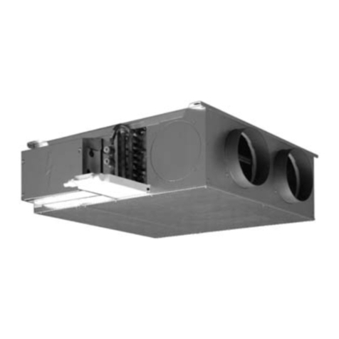
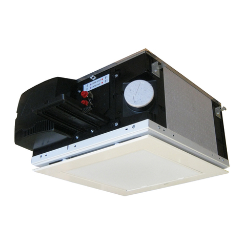
The COADIS LINE™ (CDL) unit that you have just purchased is part of a range of comfort units designed for
integration into a suspended ceiling. It is used for heating, cooling, dehumidication and air ltration. It includes a
coil with one or two hot water or cold water supply circuits and may include an electrical heater for heating.
a - Heat exchange coil
b - Fan motor assembly
c - Electrics box
d - Main condensate drain pan
e - Auxiliary condensate drain pan
f - Condensate drain
g - Support brackets
h - Air lter
j - Air return/discharge panel
k - Fresh air inlet
3.1 - Data plate (Fig. 2)
1 - Code
2 - Serial number
3 - Description of the unit
4 - Rated motor output
5 - Motor rotation speed
6 - Coil type
7 - Wiring diagram reference
8 - Motor speed wiring
9 - Maximum service pressure
10 - Electric heater specications (if tted).
11 - EC declaration number
The data plate contains all the information required to identify the unit and its conguration. This plate is positioned
on the technical face containing all the connections, above the fresh air inlet.
Before contacting us, please note the serial no. and the designation.
This device may be used by children aged eight and over, and by persons with limited physical,
sensory or mental capabilities, or by persons with insucient experience or knowledge, provided
that they are being correctly supervised or provided they have received instructions on how to
use the device in complete safety, ensuring that they have a full understanding of any risks
involved. Children must not be allowed to play with the device. User cleaning and maintenance
must not be performed by children.
During normal use, this device is intended to operate under the following site conditions:
■ Maximum altitude: 2000 m,
■ Minimum and maximum storage temperatures; -20°C + 65°C,
■ Minimum and maximum operating temperatures; 0°C +40°C,
■ Indoor return air maximum humidity level: 27°C DB (dry bulb) at 65% RH (relative humidity),
■ Clean interior environment (no oxidizing agents present).
The device requires protection from any form of impact during use. Protection rating IP 20 IK02.
This device is designed to operate in an over-voltage category II and pollution degree 2 environment, in accordance
with IEC standard 664-1.
To ensure a pollution degree 2 environment, the device must be protected from water and oil splashes, and the
dust allowed to settle on it must be limited.
COADIS LINETM 600 EN-16

4 - INSTALLATION AND CONNECTIONS
To prevent injury or damage to the unit or room, the hydraulic connections must only be made by
qualied personnel.
4.1 - Mechanical connections
Ensure there are no obstacles in order to guarantee optimal air distribution.
An electrostatic lm applied to the air intake prevents dust from entering the unit during assembly and can be left
in place until the diuser is tted in its nal position.
The air handling box is placed inside the suspended ceiling, at the edge of the room with the air discharge opposite
windows and the electrical box facing the interior of the building for models with a Visual 180° return/discharge
panel (Fig. 4 - a).
For Visual 360 ° models, position the box in the centre of the room (Fig. 4 - b), with the electrics box oriented towards
the building's interior. Ensure that the neighbouring suspended ceiling panels can be easily removed to allow
maintenance and servicing operations to be carried out. To facilitate positioning of the unit, we recommend that
you remove one of the T-shaped proles. The COADIS LINE™ must be suspended from the ceiling using 4 threaded
rods (not supplied) either 6 mm or 8 mm in diameter, which are xed to the unit's 4 support brackets using antivibration
resilient mounts (optional, Fig. 3 - a) or a nut/washer assembly positioned on either side of the mounting bracket
(Fig. 3 - b)
Note: To enable access to the auxiliary condensate drain pan and to the electrical and hydraulic connections,
a ap must be provided or access must be possible via adjacent panels in the suspended ceiling.
CIAT strongly recommends the use of antivibration resilient mounts when securing the unit, in order to reduce the
transmission of vibrations through the building structure during operation.
The tting template found in the air handling box packaging is used to trace the anchoring points for the threaded
rods onto the ceiling.
Insert the threaded rods in the notches on the support brackets.
The unit must be level and rest gently on the base of the T-shaped proles in the suspended ceiling (Fig. 3 - c) or
between the proles depending on the type of tting (Fig. 3 - d).
■Check that the impeller rotates freely and that there is no friction. If necessary, readjust the
plastic inlet (Fig. 9, a) tted to the air intake under the main pan, by gently loosening the 3
mounting bolts (Fig. 9, b). This check must be performed each time the main condensate drain
pan is disassembled and before the unit is switched back on.
■The unit must be perfectly level in relation to the suspended ceiling to prevent condensate
draining problems.
■For congurations with a Visual 180°, return/discharge panel, the rear of the unit must be a
sucient distance from the wall (at least 300 mm, recommended 600 mm) to allow suitable
access to the hydraulic, electrical and air connections.
■Reminder: the air discharge is always directed towards glass partitions in order to minimise
heat ow due to radiation.
■If a room thermostat is tted, place it on an inside wall (not behind a door) and at a height of
1,50 m from the oor. Keep it away from sunlight and all sources of heat.
4.2 - Air connections
Air quality
Comfort units are not designed to control the humidity of outside air. Fresh air handling must be provided by an
independent system in accordance with accepted engineering practice (see CIAT air handling unit ranges).
EN-17 COADIS LINETM 600

Fitting the Visual 180 ° or Visual 360 ° return/discharge panel:
We recommend tting this component only when the box is already installed in the suspended ceiling to prevent
damage to the panel or clogging of the lter during tests when switching on for the rst time.
■ Remove the electrostatic lm applied to the box's air intake.
■ Open and remove the intake grille on the nozzle (Fig. 5, a).
■ Fit the panel (Fig. 5, b). Warning: for improved eciency, direct the Visual 180° nozzle towards the glass walls.
■ Pivot the 4 bolts to hold the nozzle in position (Fig. 5, c).
■ Tighten the 4 bolts (Fig. 5, d).
■ Ret and close the intake grille again.
Do not press hard on the corners of the panel as this could deform them. Check that the panel is
securely axed.
The COADIS LINE™ has a directly integrated return/discharge interface which is able to isolate the ow of air
handled by the unit from the suspended ceiling. The use of a connecting air duct between the air return and discharge
is therefore not necessary.
The COADIS LINE™ has an inlet for clean fresh air equipped with a 100 mm diameter connection sleeve integrated
in the frame, with a removable plug (Fig. 6 - a). Recommended max fresh air ow 90 m3/h.
When using the COADIS LINE™ with fresh air, as a ltration cassette according to standard VDI 6022, the air
handling unit must full the criteria for this standard and must be equipped with an F7 lter as a minimum.
The ducts used may be coated with an anti-condensation material. (Fibreglass 12-25 mm thick)
■ Remove the plug from the fresh air inlet.
■ Position the duct on the connection sleeve.
■ Place a retaining clamp around the duct in contact with the connection sleeve.
■ Tighten the clamp and check the integrity of the connection.
To protect itself eects of condensation (no open valve when the ventilation is cut).
4.3 - Hydraulic connections
Water always ows into the bottom of the coil and exits at the top.
The pipes are positioned in the suspended ceiling as shown in Fig. 7.
The coils are equipped with a header coupling with at face swivel nuts with a female thread, diameter G½˝ and
an O-ring. (Supplied by CIAT) .
The header coupling is equipped with an air bleed valve (Fig. 8 - a) at the high point with partial draining at the low
points (Fig. 8 - b) that can be manoeuvred using a 7 mm Allen key or a at-blade screwdriver.
Recommendations for venting or draining the unit
Before carrying out work on the unit, check that the power supply is cut o and locked.
Only experienced, qualied technicians may perform installation and maintenance work on the machine. They must
be provided with personal protective equipment (PPE).
The technician must take all the necessary precautions to recover the water drained during venting or draining
procedures.
4 - INSTALLATION AND CONNECTIONS
COADIS LINETM 600 EN-18

He must pay particular attention to the risks of overowing and splashes.
■To vent the air, loosen the drain screw (Fig.8, rep. a) by a maximum of 3 turns.
■To drain the unit, ensure the unit is hydraulically isolated from the network and loosen the drain screw (Fig.8,
rep. b) by a maximum of 3 turns.
The coil can be partially drained, however precautions must be taken during winter if the installation
is shut down. To drain completely, air must be blown through the circuit.
If the hydraulic connections are completed, it is not necessary to insulate the valves to prevent
condensation (unless they are specic valves). A naturally inclined ABS auxiliary condensate
drain pan is supplied with the unit. This recovers condensate from the valves and coil (from the
main pan) and drains it via gravity or using a condensate drain pump supplied as an option.
Installation
To avoid damaging the CIAT valves or couplings, never torque tighten to more than 3,5 daN.m.
Use two wrenches, one to hold and the other to tighten to ensure a tight seal.
Always t the valve in the right direction. On the 2 CIAT couplings, the direction of ow should
be A → AB (A being connected to the coil and AB to the hydraulic network).
The maximum allowable dierential pressure for our valves (open or closed) is 100 kPa. We recommend not
exceeding 60 kPa. Refer to the valve manual for specic supplies.
Design
The positioning of the hydraulic networks is crucial to the correct operation of the system. Drain valves should
therefore be placed at the appropriate points and in sucient number. In addition, strainers should be tted, as well
as drains at circuit high points, balancing tees and shut-o valves on each coil and, if necessary, discharge valves.
Pressure safety:
The installation must be protected against any risk of overpressure. Special care must be taken to protect against
the risks linked to expansion of the energy transfer uid and to the total hydrostatic pressure.
Filtration:
An ecient ltration system (recommended eciency of 0,5 mm) should be tted on the supply water and return
water lines.
Flushing:
The system must be ushed completely and lled with treated water to prevent the build-up of scale or sludge in
the circuit. When ushing the system, open the thermo or modulating valve on the unit to prevent any sludge or
impurities from entering the coil:
4 - INSTALLATION AND CONNECTIONS
EN-19 COADIS LINETM 600

■Opening the thermo valve:
There are two options:
1) Remove the servomotor and t the cap, which will cause pressure to be applied to the shaft, thereby opening
the valve.
2) Request that the control valve opens via the controller.
A
B
AB
■Opening the 3-position modulating valves:
There are two options:
1) If the power has not yet been switched on, the valve will be open by default.
2) If the control has already been powered up, remove the servomotor to release the rod and open the valve.
A
B
AB
Filling
Drain the coils during commissioning.
Water quality recommended for water coils
It is recommended to carry out a bacteriological analysis (detection of ferrobacteria, bacteria producing H2S and
reducing sulphates) and a chemical analysis (to avoid problems with scaling and corrosion) of the water.
■ Total hardness (French scale) 10 < TH < 15
■ Chloride [CL-] < 10 mg/l
■ Sulphate [SO42-] < 30 mg/l
■ Nitrate [NO3-] = 0 mg/l
■ Dissolved iron < 0,5 mg/l
■ Dissolved oxygen 4 < [O2] < 9 mg/l
■ Carbon dioxide [CO2] < 30 mg/l
■ Resistivity 2000 < Resistivity < 5000 Ωcm
■ pH 6,9 < pH < 8
Operating limit recommendations:
■ Cooling coil inlet minimum water temperature: 6°C
■ Heating coil inlet maximum water temperature (2-tube application without electrical heaters): 70°C
■ Heating coil inlet maximum water temperature (2-tube application without electrical heaters): 55°C (min. air ow
rate = 200 m3/h)
■ Heating coil inlet maximum water temperature (4-tube application): 80°C
■ Maximum operating pressure: 16 Bar
4 - INSTALLATION AND CONNECTIONS
COADIS LINETM 600 EN-20
Other manuals for COADIS LINE 600
2
Table of contents
Other CIAT Air Conditioner manuals

CIAT
CIAT Coadis 235/11 User manual

CIAT
CIAT Major 2 CV Series User manual

CIAT
CIAT Major Series User manual

CIAT
CIAT Melody 2 User manual

CIAT
CIAT MELODY Guide

CIAT
CIAT CiatCooler LC User manual

CIAT
CIAT SPACE ZV Series Guide

CIAT
CIAT CONDENCIAT CL2 User manual

CIAT
CIAT twist SW Series User manual

CIAT
CIAT Climaciat User manual

CIAT
CIAT 42HV09JS8C User manual

CIAT
CIAT 42HV09JSC User manual

CIAT
CIAT 42HY18V User manual

CIAT
CIAT COMFORT LINE User manual

CIAT
CIAT EREBA 8H User manual

CIAT
CIAT Major2 NCH Guide

CIAT
CIAT COADIS LINE 600 User manual

CIAT
CIAT 42HU18VSC User manual
CIAT
CIAT Magister 2 Series Guide
CIAT
CIAT Splitciat SEO User manual