CIAT EREBA 8H User manual

01-2016
N 15.26B
EREBA 4 - 15kW
Installation manual

2
ENGLISH FRANCAIS DEUTSCH
Contents
1 - IntroduCtIon ........................................... 12
1.1 - R-410A - General info................................... 12
2 - safety proCedures.............................. 13
2.1 - General notes.................................................. 13
2.2 - Units handling................................................. 13
2.3 - Units installation ............................................ 13
2.4 - Electrical connections.................................... 14
2.5 - Servicing and maintenance............................ 14
3 - dImensIons and ClearanCes ......... 14
4 - teChnICal data ....................................... 15
5 - InstallatIon.............................................. 15
5.1 - Opening cable knockouts (Fig. 4)................. 15
5.2 - How to remove the front panel (Fig. 5) ....... 15
5.3 - Drain hose and base pan knockouts (Fig. 6)15
5.4 - Operating limits (Fig. 7/8).............................. 15
6 - Water ConneCtIons.............................. 16
6.1 - Hydronic module (Fig. 9/10) ......................... 16
6.2 - Water connections (Fig. 12)........................... 16
6.3 - Recommended water diagram (Fig. 11)....... 17
7 - eleCtrICal ConneCtIons (fIg. 14). 18
8 - auxIlIary aCCessorIes
ConneCtIon (fIg. 14)..................................... 19
8.1 - 3-way valve...................................................... 19
8.2 - Frequency limitation...................................... 19
8.3 - Stop unit or defrosting signals ...................... 19
8.4 - External temperature probe ......................... 19
8.5 - Dehumidier or Humidier.......................... 19
8.6 - Additional water pump (ADD WP) ............ 19
8.7 - Signal for requesting an External Heat
Source (EHS).......................................................... 20
8.8 - External alarm input...................................... 20
8.9 - Backup heater needed for sanitary
hot water.................................................................. 20
8.10 - Terminal strip pin.......................................... 20
9 - system test ................................................. 21
9.1 - Inverter board alarm codes (only for
EREBA) (Fig. 13)................................................... 21
9.2 - Inverter board alarm codes (only for sizes
15H 1Ph and 12HT-15HT 3Ph) (Fig. 13).............. 22
9.3 - GMC Board alarm codes (Fig. 13) ............... 23
10 - unIt proteCtIon devICes................ 23
11 - maIntenanCe........................................... 23
11.1 - Refrigerant charge check ............................ 23
1 - eInfÜhrung................................................ 36
1.1 - R-410A - Allgemeine Hinweise.................... 36
2 - sICherheItsInformatIonen............ 37
2.1 - Allgemeine Informationen............................ 37
2.2 - Anwendung der Geräte ................................. 37
2.3 - Installation der Geräte .................................. 37
2.4 - Stromanschlüsse ............................................. 38
2.5 - Service und Wartung...................................... 38
3 - masse und mIndest-freIräume .... 39
4 - teChnIsChe daten.................................. 39
5 - InstallatIon.............................................. 39
5.1 - Öffnungsprozedur der Rohrdur-
chgänge (Abb. 4)..................................................... 39
5.2 - Entfernen der Frontplatte (Abb. 5) ............. 39
5.3 - Kondenswasserablaufrohr und vorgestanzte
Sockelöffnungen (Abb. 6)...................................... 39
5.4 - Betriebs-Grenzwerte (Abb. 7/8)................... 39
6 - hydraulIsChen ansChlÜsse .......... 40
6.1 - Hydronikmodul (Abb. 9/10).......................... 40
6.2 - Hydraulischen Anschlüsse (Abb. 12)........... 40
6.3 - Empfohlener Hydraulikschaltplan (Fig. 11) 41
7 - elektrIsChe ansChlÜsse (abb. 14)42
8 - ansChluss der hIlfsstromkreIse
des Zubehörs (abb. 14) .............................. 43
8.1 - 3-Wegeventil ................................................... 43
8.2 - Frequenzbeschränkung.................................. 43
8.3 - Signale Gerätehalt oder Abtauung .............. 43
8.4 - Außentemperaturfühler................................. 43
8.5 - Entfeuchter oder Befeuchter........................ 43
8.6 - Zusätzliche Wasserpumpe (ADD WP)........ 43
8.7 - Signal für Anforderung einer externen
Wärmequelle oder Luftentfeuchtung (EHS)...... 44
8.8 - Eingabe Externes Alarm ............................... 44
8.9 - Reservewärmequelle für heißes
Brauchwasser nötig ................................................ 44
8.10 - Terminal strip pin.......................................... 44
9 - prÜfung des systems........................... 45
9.1 - Fehlercodes Inverter (nur für EREBA)
(Abb. 13).................................................................. 45
9.2 - Alarmcodes der Inverterplatine (nur für
grössen 15H 1Ph und 12HT-15HT 3Ph)
(Abb. 13).................................................................. 46
9.3 - Fehlercodes Platine GMC (Abb. 13) ........... 47
10 - sChutZvorrIChtungen des
gerätes .............................................................. 47
11 - geräteWartung................................... 47
11.1 - Prüfung der Kältemittelfüllung .................. 47
sommaIre
1 - IntroduCtIon ........................................... 24
1.1 - R-410A - Généralités..................................... 24
2 - InformatIons de séCurIté .............. 25
2.1 - Généralités...................................................... 25
2.2 - Emploi des unités........................................... 25
2.3 - Installation des unités .................................... 25
2.4 - Raccordements électriques ........................... 26
2.5 - Assistance et entretien................................... 26
3 - dImensIons et dégagements
mInImal............................................................... 27
4 - InformatIons teChnIques............... 27
5 - InstallatIon.............................................. 27
5.1 - Procédure d’ouverture des passages
tuyaux (Fig. 4).......................................................... 27
5.2 - Mode de démontage du panneau
avant (Fig. 5)............................................................ 27
5.3 - Tuyau d’évacuation des condensats et trous
prédécoupés de la base (Fig. 6) ............................. 27
5.4 - Limites de fonctionnement (Fig. 7/8)........... 27
6 - raCCordements hydraulIques.. 28
6.1 - Hydronic module (Fig. 9/10) ......................... 28
6.2 - Raccordements hydrauliques (Fig. 12) ........ 28
6.3 - Schéma hydraulique conseillé (Fig. 11) ....... 29
7 - raCCordements éleCtrIques
(fIg. 14)................................................................... 30
8 - branChement aCCessoIres
auxIlIaIres (fIg. 14) ..................................... 31
8.1 - Vanne à 3 voies ............................................... 31
8.2 - Limitation de fréquence ................................ 31
8.3 - Signaux Stop Unité ou Dégivrage................ 31
8.4 - Sonde de température extérieure................. 31
8.5 - Déshumidicateur ou Humidicateur......... 31
8.6 - Pompe à eau supplémentaire (ADD WP)... 31
8.7 - Signal pour demande d’une source de chaleur
extérieure (EHS) .................................................... 32
8.8 - Entrée alarme extérieure .............................. 32
8.9 - Chauffage d’appoint nécessaire pour l’eau
chaude sanitaire ...................................................... 32
8.10 - Broches Bornier ........................................... 32
9 - test de fonCtIonnement.................. 33
9.1 - Codes alarmes carte variateur (seulement
pour EREBA (Fig. 13) ........................................... 33
9.2 - Codes alarmes carte variateur (uniquement
pour les tailles 15H 1Ph et 12HT-15HT 3Ph)
(Fig. 13) ................................................................... 34
9.3 - Codes d’alarmes carte GMC (Fig. 13).......... 35
10 - dIsposItIfs de proteCtIon de
l’unIté.................................................................. 35
11 - entretIen .................................................. 35
11.1 - Vérier la charge de liquide frigorigène.... 35
Inhalt

3
ITALIANO
1 - presentaZIone......................................... 48
1.1 - Informazioni generali R-410A...................... 48
2 - proCedure dI sICureZZa.................. 49
2.1 - Informazioni generali..................................... 49
2.2 - Utilizzo delle unità......................................... 49
2.3 - Installazione delle unità................................. 49
2.4 - Collegamenti elettrici..................................... 50
2.5 - Assistenza e manutenzione ........................... 50
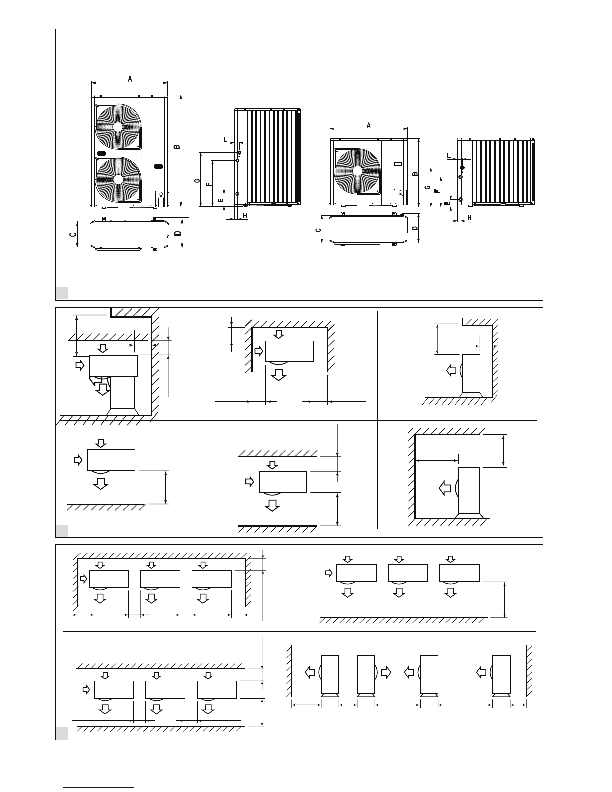
3 - dImensIonI e spaZI mInImI................. 51
4 - datI teCnICI ................................................ 51
5 - InstallaZIone .......................................... 51
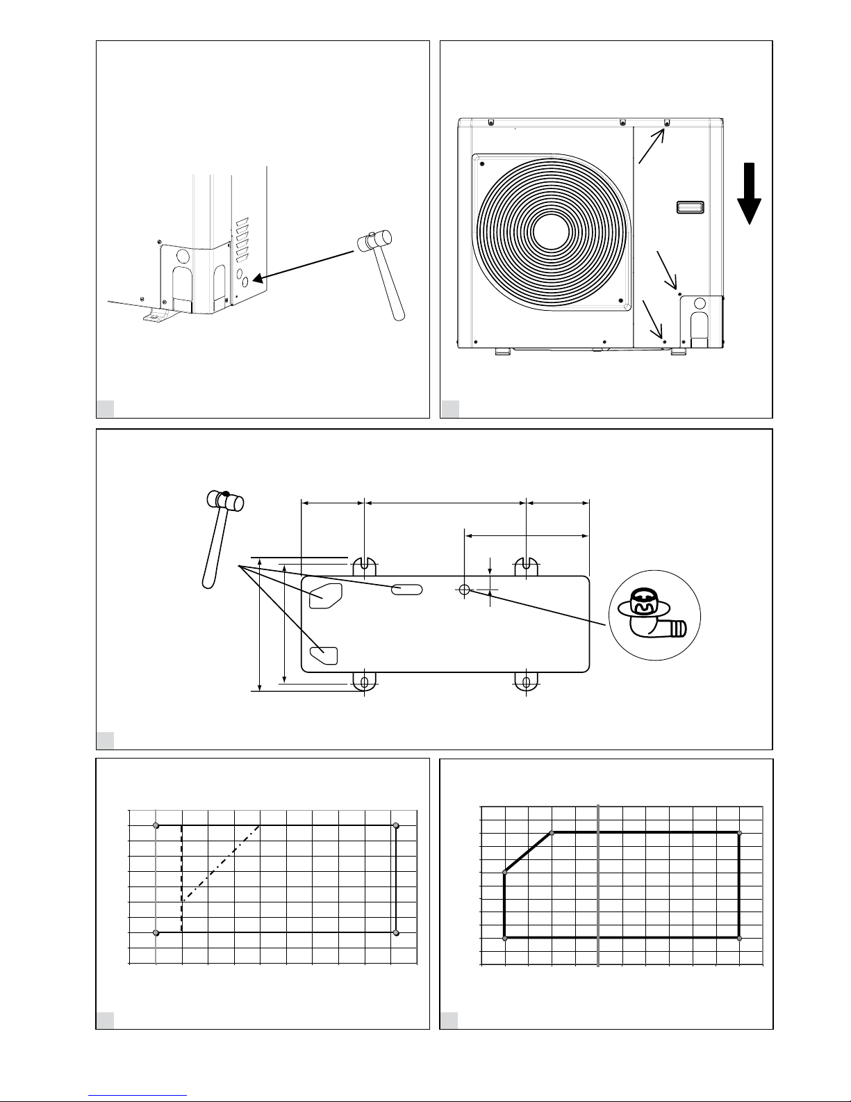
5.1 - Procedura di apertura passaggio
cavi (Fig. 4) .............................................................. 51
5.2 - Modalità di rimozione del pannello
anteriore (Fig. 5) ..................................................... 51
5.3 - Tubo di scarico condensa e fori pretranciati
della base (Fig. 6) .................................................... 51
5.4 - Limiti di funzionamento (Fig. 7/8)................ 51
6 - CollegamentI IdraulICI .................. 52
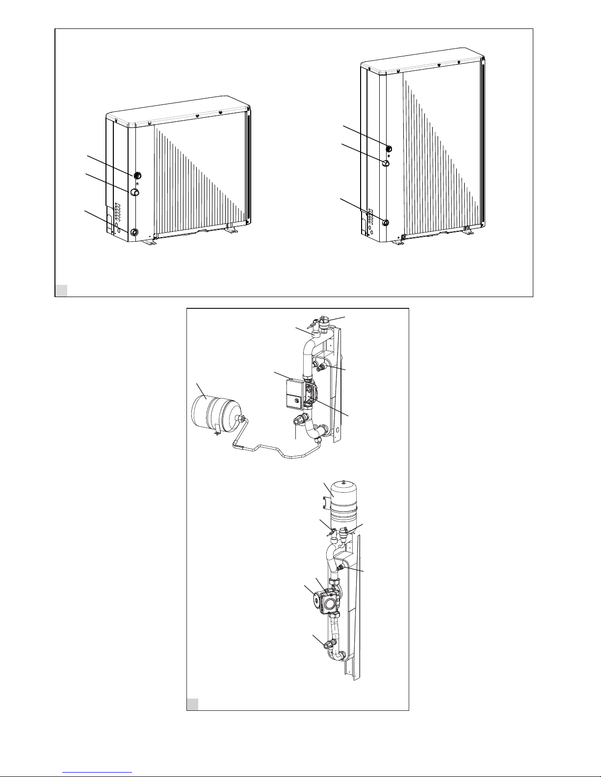
6.1 - Modulo idronico (Fig. 9/10)........................... 52
6.2 - Collegamenti idraulici (Fig. 12) .................... 52
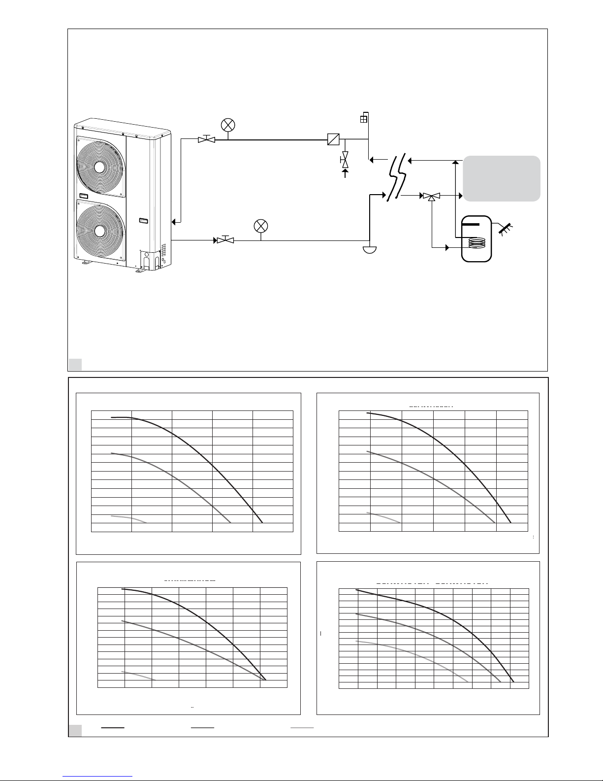
6.3 - Schema Idraulico Consigliato (Fig. 11)........ 53
7 - CollegamentI elettrICI (fIg. 14) . 54
8 - Collegamento aCCessorI
ausIlIarI (fIg. 14) ........................................... 55
8.1 - Valvola 3-vie.................................................... 55
8.2 - Limitazione Frequenza.................................. 55
8.3 - Segnali di Stop Unità o Sbrinamento........... 55
8.4 - Sonda di Temperature Esterna ..................... 55
8.5 - Deumidicatore o Umidicatore ................. 55
8.6 - Circolatore d’acqua aggiuntivo (ADD WP)55
8.7 - Segnale per richiesta di una Fonte di Calore
Esterna (EHS) ........................................................ 56
8.8 - Ingresso allarme esterno................................ 56
8.9 - Richiesta Sorgente Ausiliaria per produzione
acqua calda sanitaria .............................................. 56
8.10 - Pin Morsettiera............................................. 56
9 - verIfICa del sIstema........................... 57
9.1 - Codici allarmi scheda inverter (solo perr
EREBA) (Fig. 13)................................................... 57
9.2 - Codice allarmi scheda inverter (solo per le
taglie 15H 1Ph e 12HT-15HT 3Ph) (Fig. 13)........ 58
9.3 - Codici di Allarmi scheda GMC (Fig. 13) ..... 59
10 - dIsposItIvI dI proteZIone unItà 59
11 - manutenZIone ....................................... 59
11.1 - Verica della carica refrigerante................. 59
IndICe
ESPAÑOL NEDERLANDS
tabla de materIas Inhoud
2 - veIlIgheIdsproCedures ................... 73
2.1 - Algemene opmerkingen ................................ 73
2.2 - Omgaan met de units..................................... 73
2.3 - Installatie van de units................................... 73
2.4 - Elektrische bedrading.................................... 74
2.5 - Reparaties en onderhoud.............................. 74
3 - afmetIngen en benodIgde vrIje
ruImte ................................................................. 75
4 - teChnIsChe gegevens......................... 75
5 - InstallatIe................................................. 75
5.1 - Procedure voor het openen van de
buisdoorgangen (Fig. 4).......................................... 75
5.2 - Zo verwijdert u het frontpaneel (Fig. 5) ...... 75
5.3 - Afvoerbuis en voorgevormde gaten
basishouder (Fig. 6) ................................................ 75
5.4 - Bedrijfslimieten (Fig. 7/8).............................. 75
6 - WateraansluItIngen.......................... 76
6.1 - Hydro module (Fig. 9/10) .............................. 76
6.2 - Wateraansluitingen (Fig. 12).......................... 76
6.3 - Aanbevolen Hydraulisch Schema (Fig. 11) . 77
7 - elektrIsChe aansluItIngen
(fIg. 14)................................................................... 78
8 - aansluItIng hulpaCCessoIres
(fIg. 14)................................................................... 79
8.1 - 3-wegsklep....................................................... 79
8.2 - Frequentiebeperking...................................... 79
8.3 - Signalen stop unit of ontdooien.................... 79
8.4 - Buitentemperatuurmeter .............................. 79
8.5 - Ontvochtiger of bevochtiger......................... 79
8.6 - Extra waterpomp (ADD WP) ...................... 79
8.7 - AanvraagSignaal voor een Externe
Warmtebron (EHS)................................................ 80
8.8 - Externe alarminvoer...................................... 80
8.9 - Backupverwarming is nodig voor sanitair
warm water.............................................................. 80
8.10 - Pin Klemmenbord........................................ 80
9 - systeemtest ............................................... 81
9.1 - Alarmcodes kaart inverter (alleen
EREBA) (Fig. 13)................................................... 81
9.2 - Alarmcodes kaart inverter (Alleen voor typen
15H 1Ph en 12HT-15HT 3Ph) (Fig. 13)................ 82
9.3 - Alarmcodes GMC Kaart (Fig. 13)................ 83
10 - besChermIngsmeChanIsmen
unIt........................................................................ 83
11 - onderhoud.............................................. 83
11.1 - Controle koudemiddelvulling..................... 83
1 - IntroduCCIÓn........................................... 60
1.1 - R-410A - Informacion general...................... 60
2 - proCedImIentos de segurIdad.... 61
2.1 - Informaciones generales................................ 61
2.2 - Utilización de la unidad................................. 61
2.3 - Instalación de las unidades............................ 61
2.4 - Conexiones eléctricas..................................... 62
2.5 - Asistencia y mantenimiento.......................... 62
3 - dImensIones y espaCIos lIbres ..... 63
4 - datos téCnICos......................................... 63
5 - InstalaCIÓn................................................ 63
5.1 - Procedimiento de apertura de los pasos de los
tubos (Fig. 4)............................................................ 63
5.2 - Cómo extraer el panel frontal (Fig. 5) ......... 63
5.3 - Tubo de evacuación de la condensación y los
oricios precortados de la base (Fig. 6)................ 63
5.4 - Limites de funcionamiento (Fig. 7/8) ........... 63
6 - ConexIones hIdráulICas ................. 64
6.1 - Módulo hidrónico (Fig. 9/10) ........................ 64
6.2 - Conexiones hidráulicas (Fig. 12)................... 64
6.3 - Esquema Hidráulico Recomendado
(Fig. 11) ................................................................... 65
7 - ConexIones eléCtrICas (fIg. 14).... 66
8 - ConexIÓn aCCesorIos auxIlIares
(fIg. 14)................................................................... 67
8.1 - Válvula de 3 vías............................................. 67
8.2 - Limitación frecuencia .................................... 67
8.3 - Señales de Stop Unidad o Desempañado ... 67
8.4 - Sonda de Temperaturas Exteriores .............. 67
8.5 - Déshumidicateur ou Humidicateur......... 67
8.6 - Bomba de agua adicional (ADD WP)......... 67
8.7 - Señal para pedido de una Fuente de Calor
Externa (EHS)........................................................ 68
8.8 - Entrada alarma exterior ................................ 68
8.9 - Es necesario un calentador de respaldo para
agua caliente sanitaria............................................ 68
8.10 - Pin Caja de Bornes....................................... 68
9 - verIfICaCIÓn del sIstema ................ 69
9.1 - Códigos alarmas placa Convertidor (sólo para
EREBA) (Fig. 13)................................................... 69
9.2 - Inversor códigos panel de alarma
(unicamente para tamaños 15H 1Ph y 12HT-15HT
3Ph) (Fig. 13)........................................................... 70
9.3 - Códigos de Alarmas placa GMC (Fig. 13)... 71
10 - dIsposItIvos de proteCCIÓn de la
unIdad................................................................. 71
11 - mantenImIento...................................... 71
11.1 - Vericación de la carga de refrigerante ..... 71
1 - InleIdIng...................................................... 72
1.1 - R-410A - Algemene informatie .................... 72

4
2
3
1
150
500
1000
1000
150150 300300 300
200
1000
300
200
300
1000
1000 1500 2000 200
300
150
200
150 300
500
1000 150

5
600150 150
430
400
363
6
5
4
B
A
37
78
A
B
0
2
4
6
8
10
12
14
16
18
20
-5 0510 15 20 25 30 35 40 45 50
A
B
008-012-015
004
006
0
2
4
6
8
10
12
14
16
18
20
-5 0510 15 20 25 30 35 40 45 50
10
15
20
25
30
35
40
45
50
55
60
65
70
-25-20 -15-10 -5 0510 15 20 25 30 35
A
B

6
10
1
2
4
6
7
3
6
5
5
2
4
1
7
3
9
1
2
3
1
2
3
10
1
2
4
6
7
3
6
5
5
2
4
1
7
3
7
6
5
21
4
3
4
7
12
3
6
5

7
12
1
1
2
3
3
4
6
5
78
9
11
30AWH006H
0
5
10
15
20
25
30
35
40
45
50
55
60
00,1 0,20,3 0,40,5 0,6
EREBA 6H
30AWH012H
0
10
20
30
40
50
60
70
80
90
00,1 0,20,3 0,40,5 0,60,7 0,80,9
EREBA 12H - EREBA 15H
0
5
10
15
20
25
30
35
40
45
50
55
60
65
70
0,2 0,3 0,4 0,50,10,0
A
B
EREBA 4H
30AWH008H
0
5
10
15
20
25
30
35
40
45
50
55
60
00,1 0,20,3 0,40,5 0,6
EREBA 8H
BB
B
B
AA
A
A
12
30AWH006H
0
5
10
15
20
25
30
35
40
45
50
55
60
0 0,1 0,2 0,3 0,4 0,5 0,6
30AWH006H
30AWH012H
0
10
20
30
40
50
60
70
80
90
0 0,1 0,2 0,3 0,4 0,5 0,6 0,7 0,8 0,9
30AWH012H - 30AWH015H
0
5
10
15
20
25
30
35
40
45
50
55
60
65
70
0,2 0,3 0,4 0,50,10,0 A
B
30AWH004H
30AWH008H
0
5
10
15
20
25
30
35
40
45
50
55
60
0 0,1 0,2 0,3 0,4 0,5 0,6
30AWH008H
BB
B
B
AA
A
A
AA
AA
BB
B
B
0.0 0.1 0.2 0.3 0.4 0.5
5
10
15
20
25
30
35
40
45
50
55
60
65
70
75
0.0 0.1 0.2 0.3 0.4 0.5 0.6
5
10
15
20
25
30
35
40
45
50
55
60
65
70
75
0.0 0.1 0.2 0.3 0.4 0.5 0.6 0.7
5
10
15
20
25
30
35
40
45
50
55
60
65
70
75
10
20
25
30
35
40
45
50
55
60
65
70
75
80
85
90
95
0.0 0.1 0.2 0.3 0.4 0.5 0.6 0.7 0.8 0.9 1.0
High speed Medium speed Low speed
EREBA 4H EREBA 6H
EREBA 8H EREBA 12H + EREBA 15H
10
15
14
30AWH012X
0
10
20
30
40
50
60
0 0.1 0.2 0.3 0.4 0.5 0.6 0.7 0.8 0.9
30AWH006H
0
5
10
15
20
25
30
35
40
45
50
55
60
0 0,1 0,2 0,3 0,4 0,5 0,6
30AWH006H
30AWH012H
0
10
20
30
40
50
60
70
80
90
0 0,1 0,2 0,3 0,4 0,5 0,6 0,7 0,80
,9
30AWH012H - 30AWH015H
0
5
10
15
20
25
30
35
40
45
50
55
60
65
70
0,2 0,3 0,4 0,50,10,0
A
B
30AWH004H
30AWH008H
0
5
10
15
20
25
30
35
40
45
50
55
60
0 0,1 0,2 0,3 0,4 0,5 0,6
30AWH008H
30AWH006X
0
5
10
15
20
30
35
40
45
50
55
0 0.1 0.2 0.3 0.4 0.5 0.6
30AWH006X
30AWH004X
30AWH012X - 30AWH015X
30AWH008X
0
5
10
15
20
25
30
35
40
0 0.1 0.2 0.3 0.4 0.5 0.6
30AWH008X
B
B
B
B
B
A
A
A
A
B
B
B
AA
A
A
AA
AA
BB
B
B
30AWH012H + 015H30AWH 008H
30AWH 006H30AWH 004H
0.0 0.1 0.2 0.3 0.4 0.5
5
10
15
20
25
30
35
40
45
50
55
60
65
70
75
0.0 0.1 0.2 0.3 0.4 0.5 0.6
5
10
15
20
25
30
35
40
45
50
55
60
65
70
75
0.0 0.1 0.2 0.3 0.4 0.5 0.6 0.7
5
10
15
20
25
30
35
40
45
50
55
60
65
70
75
10
20
25
30
35
40
45
50
55
60
65
70
75
80
85
90
95
0.0 0.1 0.2 0.3 0.4 0.5 0.6 0.7 0.8 0.9 1.0
25
0.0 0.1 0.2 0.3 0.4 0.5
0
5
10
15
20
25
30
35
40
45
50
55
60
65
70
High speed Medium speed Low speed
10
15
14
30AWH012X
0
10
20
30
40
50
60
0 0.1 0.2 0.3 0.4 0.5 0.6 0.7 0.8 0.9
30AWH006H
0
5
10
15
20
25
30
35
40
45
50
55
60
0 0,1 0,2 0,3 0,4 0,5
0,6
30AWH006H
30AWH012H
0
10
20
30
40
50
60
70
80
90
0 0,1 0,2 0,3 0,4 0,5 0,6 0,7 0,80
,9
30AWH012H - 30AWH015H
0
5
10
15
20
25
30
35
40
45
50
55
60
65
70
0,2 0,3 0,4 0,50,10,0
A
B
30AWH004H
30AWH008H
0
5
10
15
20
25
30
35
40
45
50
55
60
0 0,1 0,2 0,3 0,4 0,5 0,6
30AWH008H
30AWH006X
0
5
10
15
20
30
35
40
45
50
55
0 0.1 0.2 0.3 0.4 0.5 0.6
30AWH006X
30AWH004X
30AWH012X - 30AWH015X
30AWH008X
0
5
10
15
20
25
30
35
40
0 0.1 0.2 0.3 0.4 0.5 0.6
30AWH008X
B
B
B
B
B
A
A
A
A
B
B
B
AA
A
A
AA
A
A
BB
B
B
30AWH012H + 015H30AWH 008H
30AWH 006H30AWH 004H
0.0 0.1 0.2 0.3 0.4 0.5
5
10
15
20
25
30
35
40
45
50
55
60
65
70
75
0.0 0.1 0.2 0.3 0.4 0.5 0.6
5
10
15
20
25
30
35
40
45
50
55
60
65
70
75
0.0 0.1 0.2 0.3 0.4 0.5 0.6 0.7
5
10
15
20
25
30
35
40
45
50
55
60
65
70
75
10
20
25
30
35
40
45
50
55
60
65
70
75
80
85
90
95
0.0 0.1 0.2 0.3 0.4 0.5 0.6 0.7 0.8 0.9 1.0
25
0.0 0.1 0.2 0.3 0.4 0.5
0
5
10
15
20
25
30
35
40
45
50
55
60
65
70
High speed Medium speed Low speed
10
15
14
30AWH012X
0
10
20
30
40
50
60
0 0.1 0.2 0.3 0.4 0.5 0.6 0.7 0.8 0.9
30AWH006H
0
5
10
15
20
25
30
35
40
45
50
55
60
0 0,1 0,2 0,3 0,4 0,5 0,6
30AWH006H
30AWH012H
0
10
20
30
40
50
60
70
80
90
0 0,1 0,2 0,3 0,4 0,5 0,6 0,7 0,80
,9
30AWH012H - 30AWH015H
0
5
10
15
20
25
30
35
40
45
50
55
60
65
70
0,2 0,3 0,4 0,50,10,0
A
B
30AWH004H
30AWH008H
0
5
10
15
20
25
30
35
40
45
50
55
60
0 0,1 0,2 0,3 0,4 0,5
0,6
30AWH008H
30AWH006X
0
5
10
15
20
30
35
40
45
50
55
0 0.1 0.2 0.3 0.4 0.5 0.6
30AWH006X
30AWH004X
30AWH012X - 30AWH015X
30AWH008X
0
5
10
15
20
25
30
35
40
0 0.1 0.2 0.3 0.4 0.5 0.6
30AWH008X
BB
B
B
B
AA
A
A
B
B
B
AA
A
A
A
A
AA
B
B
B
B
30AWH012H + 015H30AWH 008H
30AWH 006H30AWH 004H
0.0 0.1 0.2 0.3 0.4 0.5
5
10
15
20
25
30
35
40
45
50
55
60
65
70
75
0.0 0.1 0.2 0.3 0.4 0.5 0.6
5
10
15
20
25
30
35
40
45
50
55
60
65
70
75
0.0 0.1 0.2 0.3 0.4 0.5 0.6 0.7
5
10
15
20
25
30
35
40
45
50
55
60
65
70
75
10
20
25
30
35
40
45
50
55
60
65
70
75
80
85
90
95
0.0 0.1 0.2 0.3 0.4 0.5 0.6 0.7 0.8 0.9 1.0
25
0.0 0.1 0.2 0.3 0.4 0.5
0
5
10
15
20
25
30
35
40
45
50
55
60
65
70
High speed Medium speed Low speed
10
15
14
30AWH012X
0
10
20
30
40
50
60
0 0.1 0.2 0.3 0.4 0.5 0.6 0.7 0.8 0.9
30AWH006H
0
5
10
15
20
25
30
35
40
45
50
55
60
0 0,1 0,2 0,3 0,4 0,5 0,6
30AWH006H
30AWH012H
0
10
20
30
40
50
60
70
80
90
0 0,1 0,2 0,3 0,4 0,5 0,6 0,7 0,
80
,9
30AWH012H - 30AWH015H
0
5
10
15
20
25
30
35
40
45
50
55
60
65
70
0,2 0,3 0,4 0,50,10,0
A
B
30AWH004H
30AWH008H
0
5
10
15
20
25
30
35
40
45
50
55
60
0 0,1 0,2 0,3 0,4 0,5 0,6
30AWH008H
30AWH006X
0
5
10
15
20
30
35
40
45
50
55
0 0.1 0.2 0.3 0.4 0.5 0.6
30AWH006X
30AWH004X
30AWH012X - 30AWH015X
30AWH008X
0
5
10
15
20
25
30
35
40
0 0.1 0.2 0.3 0.4 0.5 0.6
30AWH008X
BB
B
B
B
AA
A
A
B
B
B
AA
A
A
AA
AA
B
B
B
B
30AWH012H + 015H30AWH 008H
30AWH 006H30AWH 004H
0.0 0.1 0.2 0.3 0.4 0.5
5
10
15
20
25
30
35
40
45
50
55
60
65
70
75
0.0 0.1 0.2 0.3 0.4 0.5 0.6
5
10
15
20
25
30
35
40
45
50
55
60
65
70
75
0.0 0.1 0.2 0.3 0.4 0.5 0.6 0.7
5
10
15
20
25
30
35
40
45
50
55
60
65
70
75
10
20
25
30
35
40
45
50
55
60
65
70
75
80
85
90
95
0.0 0.1 0.2 0.3 0.4 0.5 0.6 0.7 0.8 0.9 1.0
25
0.0 0.1 0.2 0.3 0.4 0.5
0
5
10
15
20
25
30
35
40
45
50
55
60
65
70
High speed Medium speed Low speed
10
15
14
30AWH012X
0
10
20
30
40
50
60
0 0.1 0.2 0.3 0.4 0.5 0.6 0.7 0.8 0.9
30AWH006H
0
5
10
15
20
25
30
35
40
45
50
55
60
0 0,1 0,2 0,3 0,4 0,5 0,6
30AWH006H
30AWH012H
0
10
20
30
40
50
60
70
80
90
0 0,1 0,2 0,3 0,4 0,5 0,6 0,7 0,80
,9
30AWH012H - 30AWH015H
0
5
10
15
20
25
30
35
40
45
50
55
60
65
70
0,2 0,3 0,4 0,50,10,0
A
B
30AWH004H
30AWH008H
0
5
10
15
20
25
30
35
40
45
50
55
60
0 0,1 0,2 0,3 0,4 0,5 0,6
30AWH008H
30AWH006X
0
5
10
15
20
30
35
40
45
50
55
0 0.1 0.2 0.3 0.4 0.5 0.6
30AWH006X
30AWH004X
30AWH012X - 30AWH015X
30AWH008X
0
5
10
15
20
25
30
35
40
0 0.1 0.2 0.3 0.4 0.5 0.6
30AWH008X
BB
B
B
B
AA
A
A
B
B
B
AA
A
A
AA
AA
BB
B
B
30AWH012H + 015H30AWH 008H
30AWH 006H30AWH 004H
0.0 0.1 0.2 0.3 0.4 0.5
5
10
15
20
25
30
35
40
45
50
55
60
65
70
75
0.0 0.1 0.2 0.3 0.4 0.5 0.6
5
10
15
20
25
30
35
40
45
50
55
60
65
70
75
0.0 0.1 0.2 0.3 0.4 0.5 0.6 0.7
5
10
15
20
25
30
35
40
45
50
55
60
65
70
75
10
20
25
30
35
40
45
50
55
60
65
70
75
80
85
90
95
0.0 0.1 0.2 0.3 0.4 0.5 0.6 0.7 0.8 0.9 1.0
25
0.0 0.1 0.2 0.3 0.4 0.5
0
5
10
15
20
25
30
35
40
45
50
55
60
65
70
High speed Medium speed Low speed

8
13
C
B
12 kW 1Ph4, 6, 8 kW 1Ph
12, 15 kW 3Ph15 kW 3Ph
C
D
A
D
C
E
A
C
E
A
D
C

9
6
7
EREBA
9
5
4
1
2
N
3
N 18 10 11 12 4 5 16
8
C W G Y 13 14 15 7 6 3 2 1 8 21 23 24
CS1
Remote control
L N
10
10
LΝ
30 40
1Ph
3Ph
11
L1 L2 L3
N
12−15 3Ph
L N
LN
15kW 1Ph
10 50
10 40
14

10
Figure titles and legends:
1 Dimensions
2 Clearances (single installation)
3 Clearances (serial installation)
4 Opening cable knockouts
5 Removing front panel
6 Drain hose and base pan knockouts
A Drain nipple
B Soft-faced hammer
7 Operating limits (cooling)
A Outdoor air temperature (°C)
B Outlet water temperature (°C)
8 Operating limits (heating)
A Outdoor air temperature (°C)
B Outlet water temperature (°C)
9 Water connections
1 Entering water pipe
2 Leaving water pipe
3 Draining water pipe
10 Integrated water circuit
1 Automatic purge valve
2 Flow switch
3 Safety valve (outlet 1/2’)
4 Temperature probe
5 Circulation pump
6 Plug to unblock the seizing pump
7 Expansion vessel
11 Typical water circuit diagram
1 Shut-ovalves
2 Linelterforwater(10mesh/cm2)
3 Pressure gauges
4 Filling valve
5 System drain valve
(at the lowest points of the circuit)
6 Airushingvalve
(in the highest parts of the circuit)
7 3-way valve
8 Sanitary water accumulation tank
9 Inside system
12 Water connections
A Waterowrate(l/s)
B Available static pressure (kPa)
13 Board position
A Position 4 LED Inverter Diagnostics Board
(only EREBA 12H/HT and
EREBA 15H/HT)
B Position LED GMC Diagnostics Board
C Installation terminal strip
D Cable holder
E Strain relief
14 Auxiliary connections
1 3 Way valve
2 Backupheaterneeded/Dehumidier
3 Trace Heater / Additional Water pump
4 External heat source / Defrost
5 Alarm / Ambient temperature reached
6 Limitation frequency
7 Sanitary Input
8 Alarm Input
9 External temperature probe
(NTC3kΩ@25°C)
10 External water pump
ENGLISH FRANCAIS DEUTSCH
Figures et légendes:
1 Dimensions
2 Dégagements minimal (installation d’une unité)
3 Dégagements minimal (installation de plusieurs
unités)
4 Procédure d’ouverture des passages tuyaux
5 Mode de démontage du panneau avant
6 Tuyau d’évacuation des condensats et trous
prédécoupés de la base
A Raccorder le téton
B Marteau à face souple
7 Limites de fonctionnement (refroidissement)
A Température extérieure de l’air (°C)
B Température Eau en sortie (°C)
8 Limitesdefonctionnement(chauage)
A Température extérieure de l’air (°C)
B Température Eau en sortie (°C)
9 Raccordements hydrauliques
1 Entrée dans la conduite d’eau
2 Sortie de la conduite d’eau
3 Vidange de la conduite d’eau
10 Circuit hydraulique intégré
1 Vanne de purge d’air automatique
2 Débitmètre
3 Vanne de sécurité (sortie 1/2’)
4 Sonde de température
5 Pompe de circulation
6 Bouchonpourdéblocagepompeencas
de grippage
7 Vase d’expansion
11 Schéma hydraulique conseillé
1 Vannes de fermeture
2 Filtre de ligne pour eau (10 mailles/cm2)
3 Pompe de circulation d’eau
4 Vanne de remplissage
5 Vanne d’évacuation installation
(aux points les plus bas du circuit)
6 Vanne de purge d’air (aux points les
plus hauts du circuit)
7 Vanne à trois voies
8 Réservoir d’accumulation d’eau
sanitaire
9 Installation interne
12 Raccordements hydrauliques
A Débit d’eau (l/s)
B Chute de pression (kPa)
13 Position des cartes
A Position 4 leds Diagnostic carte
variateur (EREBA 12H/HT et EREBA
15H/HT seulement)
B Position led Diagnostic Carte GMC
C Bornier d’installation
D Guide-câbles
E Détendeur
14 Branchements auxiliaires
1 Circulateur d’eau extérieur
2 Chauaged’appointnécessaire/
Déshumidicateur
3 Chauetrace/Pompeàeau
supplémentaire
4 Source de chaleur extérieure /
Dégivrage
5 Alarme / Contact terminal ventilo-
convecteur
6 Limitation de fréquence
7 Entrée sanitaire
8 Entrée alarme
9 Capteur de température extérieure
(NTC3kΩ@25°C)
10 Pompe à eau extérieure
Abbildungen und Legende:
1 Abmessungen
2 Mindestplatzbedarf (Installation von 1 Gerät)
3 Mindestplatzbedarf (Installation von mehreren
Geräten)
4 Vorgehensweise
5 Entfernen der Frontplatte
6 Kondenswasserablassrohr und vorgestanzte
Sockelönungen
A Entwässerungsverbindungsstück
B Hammers
7 Betriebs-Grenzwerte (Kühlbetrieb)
A Außenlufttemperatur (°C)
B Wassertemperatur Austritt (°C)
8 Betriebs-Grenzwerte (Heizbetrieb)
A Außenlufttemperatur (°C)
B Wassertemperatur Austritt (°C)
9 Hydraulischen Anschlüsse
1 Wasserleitungseintritt
2 Wasserleitungsaustritt
3 Wasserablaueitung
10 Integrierter Wasserkreislauf
1 Automatische Entlüftung
2 Strömungswächter
3 Sicherheitsventil (Ausgang 1/2’)
4 Temperaturfühler
5 Umwälzpumpe
6 Stopfen zum Freisetzen der
festgelaufenen Pumpe
7 Expansionstank
11 Typisches Hydraulikkreislauf-Diagramm
1 Absperrventile
2 Wasserleitungslter(10Maschen/cm^2)
3 Wasserumwälzpumpe
4 Einfüllventil
5 Ablassventil der Anlage (an den tiefsten
Kreislaufpunkten)
6 Entlüftungsventil (an den höchsten
Kreislaufpunkten)
7 3-Wegeventil
8 Brauchwasserspeicher
9 Interne Anlage
12 Hydraulischen Anschlüsse
A Wassermenge (l/s)
B Statischer Nutzdruck (kPa)
13 Position Platine
A Position 4 LED Diagnose Platine Inverter
(nur EREBA 12H/HT und EREBA 15H/HT)
B Position LED Diagnose Platine GMC
C Installations-Klemmenleiste
D Kabeldurchgang
E Zugentlastung
14 Anschlüsse Hilfsstormkreise
1 3-Wegeventil
2 Reservewärmequelle nötig / Entfeuchter
3 Begleitheizgerät / Zusätzliche
Wasserpumpe
4 Externe Wärmequelle / Enteisen
5 Alarm / Anschlussklemme Lüfterkontakt
6 Frequenzbegrenzung
7 Sanitär Eingabe
8 Alarm Eingabe
9 Außentemperaturfühler(NTC3kΩ@25°C)
10 Externe Wasserpumpe

11
ITALIANO
Titoli e Legenda delle Figure:
1 Dimensioni
2 Spazi minimi (installazione di 1 unità)
3 Spazi minimi (installazione di più unità)
4 Proceduradisnestratura
5 Modalità di rimozione del pannello anteriore
6 Tubo di scarico condensa e fori pretranciati della
base
A Raccordo di drenaggio
B Martello
7 Limitidifunzionamento(Rareddamento)
A Temperatura Aria Esterna (°C)
B Temperatura Acqua in uscita (°C)
8 Limiti di funzionamento (Riscaldamento)
A Temperatura Aria Esterna (°C)
B Temperatura Acqua in uscita (°C)
9 Collegamenti idraulici
1 Ingresso acqua all’unità
2 Uscita acqua dall’unità
3 Scarico acqua dall’unità
10 Circuito idraulico integrato
1 valvola automatica sfogo aria
2 ussostato
3 valvola di sicurezza (uscita 1/2’)
4 sonda di temperatura
5 pompa di ricircolazione
6 tappo per sblocco pompa da grippaggio
7 vaso d’espansione
11 Schema tipico di circuito idraulico
1 valvole di intercettazione
2 ltrodilineaperacqua
10maglie/cm^2)
3 manometro
4 valvola di riempimento
5 valvoladi scarico impianto(neipuntipiù
bassi del circuito)
6 valvola di spurgo aria (nei punti più alti
del circuito)
7 valvola 3 vie
8 serbatoio di accumulo di acqua sanitaria
9 utenza interna
12 Collegamenti idraulici
A Portata (l/s)
B Pressione statica disponibile (kPa)
13 Posizione schede
A Posizione 4 Led Diagnostica Scheda
Inverter (solo EREBA 12H/HT e
EREBA 15H/HT)
B Posizione Led Diagnostica Scheda
GMC
C Morsettiera di installazione
D Fermacavo
E Pressacavo
14 Collegamenti Ausiliari
1 Valvola 3 vie
2 Allarme o Sbrinamento /
Deumidicatore
3 Trace heater/ Circolatore d’acqua
aggiuntivo
4 Sorgente di calore esterna /
Sbrinamento
5 Allarme / Segnale di Raggiunta
Temperatura Ambiente
6 Riduzione frequenza massima
7 Richiesta Acqua Sanitaria
8 Ingresso allarme esterno
9 Sensore di temperatura esterna (NTC
3k@25°C)
10 Circolatore d’acqua esterno
ESPAÑOL NEDERLANDS
1 Dimensiones
2 Espacios libres (instalación de 1 unidad)
3 Espacios libres (instalación de varias unidades)
4 Procedimiento de realización
5 Cómo extraer el panel frontal
6 Tubo de evacuación de la condensación y los
oriciosprecortadosdelabase
A Empalme de drenaje
B Martillo
7 Limites de funcionamiento (enfriamiento)
A Temperatura Aire Exterior (°C)
B Temperatura Agua en salida (°C)
8 Limites de funcionamiento (Calentamiento)
A Temperatura Aire Exterior (°C)
B Temperatura Agua en salida (°C)
9 Conexiones hidráulicas
1 Tubería de entrada de agua
2 Tubería de salida de agua
3 Tubería de drenaje de agua
10 Circuito hidráulico integrado
1 purgador automático
2 interruptordeujo
3 válvula de seguridad (salida 1/2’)
4 sonda de temperatura
5 bomba de recirculación
6 tapón para desbloqueo bomba de
agarrotamiento
7 válvulas de cierre
11 Esquema típico del circuito de agua
1 válvulas de cierre
2 ltrodelíneaparaagua(10mallas/
cm^2)
3 bomba aceleradora de agua
4 válvula de llenado
5 válvula de descarga
(en los puntos más altos del circuito)
6 válvula de purga aire
(en los puntos más altos del circuito)
7 válvula de 3 vías
8 depósito de acumulación agua sanitaria
9 sistema interno
12 Conexiones hidráulicas
A Caudal de agua (l/s)
B Presión estática disponible (kPa)
13 Posición placas
A Posición 4 Led Diagnosis Placa
Convertidor (solo EREBA 12H/HT y
EREBA 15H/HT)
B Posición Led Diagnosis Placa GMC
C Caja de Bornes de instalación
D Guíacables
E Aprieta-cable
14 Conexiones auxiliares
1 Válvula de 3 vías
2 Esnecesariouncalentadorde respaldo
/Déshumidicateur
3 Trace Heater / Bomba de agua adicional
4 Fuente de calor externa / Desescarche
5 Alarma /Contacto terminal convector
6 Limitación de frecuencia
7 Entrada sanitaria
8 Entrada alarma
9 Sensor de temperatura externa (NTC
3kΩ@25°C)
10 Bomba de agua externa
Titels van afbeeldingen en verklaringen:
1 Afmetingen
2 Benodigde vrije ruimte (enkele installatie)
3 Benodigde vrije ruimte (installatie in serie)
4 Knock-out verwijderen
5 Zo verwijdert u het frontpaneel
6 Afvoerbuis en voorgevormde gaten basishouder
A Afvoernippel
B Hamer
7 Bedrijfslimieten (Koelende functionering)
A Buitenluchttemperatuur (°C)
B Watertemperatuur aan uitgang (°C)
8 Bedrijfslimieten (Verwarmende functionering)
A Buitenluchttemperatuur (°C)
B Watertemperatuur aan uitgang (°C)
9 Wateraansluitingen
1 Waterpomp binnengaan
2 Waterpomp uitgaan
3 Waterpomp afvoeren
10 Geïntegreerd hydraulisch circuit
1 automatische ontluchting
2 stromingsschakelaar
3 overstortventiel (uitgang 1/2’)
4 temperatuurmeter
5 hercirculatiepomp
6 ontgrendelstop vastgelopen pomp
7 handbediende afsluiters
11 Voorbeeld van een watercircuit
1 afsluiters
2 lterwatercircuit(10mazen/cm^2)
3 waterpomp
4 vulkraantje
5 installatie afvoerkraantje
(op de laagste punten van het circuit)
6 ontluchtingskraantje
(op de hoogste punten van het circuit)
7 3-wegsklep
8 opslagtank sanitair water
9 interne installatie
12 Wateraansluitingen
A Waterdebiet (l/s)
B Drukval (kPa)
13 Stand kaarten
A Stand 4 Led Diagnostiek Kaart Inverter
(enkel EREBA 12H/HT en
EREBA 15H/HT)
B Stand Led Diagnostiek GMC Kaart
C Klemmenbord installatie
D Kabelbeugel
E Trekontlasting
14 Hulpaansluitingen
1 3-wegsklep
2 Backupvermarming is nodig /
Ontvochtiger
3 Trace heater / Extra waterpomp
4 Externe warmtebron /
ontdooiingsmechanisme
5 Alarm / Spoelcontact terminalventilator
6 Begrenzingfrequentie
7 Watertoevoer
8 Alarminvoer
9 Buitentemperatuursensor (NTC
3kΩ@25°C)
10 Externe waterpomp

12
English
1.1 - R-410A - General info
• This air conditioner adopts the new HFC refrigerant
(R410A) which does not destroy ozone layer.
• R-410A refrigerant operates at 50%-70% higher
pressures than R-22. Be sure that servicing equipment
and replacement components are designed to operate
with R-410A.
• R-410A refrigerant cylinders have a dip tube which
allows liquid to ow out with the cylinder in a vertical
position with the valve at the top.
• R-410A systems should be charged with liquid
refrigerant. Use a commercial type metering device in
the manifold hose in order to vaporize the liquid
refrigerant before it enters in the unit.
• As for other HFC, R-410A refrigerant is only
compatible with oils recommended by the compressor
manufacturer.
• A vacuum pump is not enough to remove moisture
from oil.
• Oils absorb moisture rapidly. Do not expose oil to
atmosphere.
• Never open system to atmosphere while it is under
vacuum.
• When the system must be opened for service, break
vacuum with dry nitrogen.
• Do not vent R-410A into the atmosphere.
Use this unit only for factory approved applications.
The capacity and unit code are stated on the nameplate
data. CAUTION:
SITINGTHE UNIT
INSTALLATION
WATER CONNECTIONS
ELECTRICAL CONNECTIONS
CONTROL WIRING (Optional)
POWERWIRING
FILLINGTHE SYSTEM
FLUSHING WATER AND AIR
CHECKING FORWATER LEAKS
CONFIGURING AND CHECKINGTHE SYSTEM

13
English
Explanation of illustrated marks
Indicates prohibited items
Indicates mandatory items
Indicates cautions (including danger/warnings)
Explanation of indications
DANGER Indicates contents will cause death or serious injury if
used incorrectly.
WARNING Indicates contents could cause death or serious injury if
used incorrectly.
CAUTION
Indicates contents could cause an injury or damage to
property, furniture or pets if the instructions are not
followed carefully.
2.1 - General notes
• Please ensure this is read thoroughly and kept for
future reference.
• Before any repairs or maintenance is carried out an
assessment of the potential risks must be undertaken,
and appropriate measures taken to ensure the safety
of all personnel.
• Do not attempt to repair, move, modify or re-install
the unit on your own.
2.1.1 - Liability
The manufacturer declines any liability and invalidate the
unit warranty for damage resulting from:
• Improper installation; including failure to follow
instructions in the manuals.
• Modications or errors in the electrical or refrigerant
or water connections.
• Use of the unit under condition other than those
indicated.
2.2 - Units handling
Ensure adequate personal protective equipment is used.
Inspect equipment for damage due to improper
transportation or handling: File an immediate claim with
the shipping company.
Dispose of the packaging material in accordance with
local requirements.
When lifting the unit, absolutely do not use hooks
inserted in the side handles, use special equipment (e.g.
lifting devices, trolleys, etc.).
Do not step or put anything on the outdoor unit. It may
cause an injury or damage the unit.
Donotplacecontainerslledwithliquidsorother
objects onto the unit.
2.3 - Units installation
• Difcult to access for installation and maintenance.
• Too close to heat sources.
• That might increase the vibration of the unit.
• Which cannot bear the weight of the unit.
• Subject to a risk of exposure to a combustible gas.
• Exposed to oils and vapours.
• With particular environmental conditions.
Outdoor unit
• Where noise and discharged air do not disturb
neighbours.
• Protected from opposing winds.
• That allows for the clearances required.
• Which will not obstruct passageways or doors.
• With oor structure adequately strong to support unit
weight and minimize vibration transmission.
Fix the unit with locally purchased bolts buried in
the block.
If the unit is installed in areas where heavy snowfalls
may occur, it is necessary to raise its level at least
200 mm above the usual snow level or alternatively
to use the outdoor unit bracket kit.

14
English
2.4 - Electrical connections
• This unit complies with Machinery Directive (2006/42/
EC), electromagnetic compatibility (2004/108/EC)
and pressure equipment (EEC/97/23) Directives.
• To avoid electric shock or re make sure these
operations are carried out by qualied personnel only.
• Ensure that national safety code requirements have
been followed for the main supply circuit.
• Follow all current national safety code requirements.
• Ensure that a properly sized and connected ground
wire is in place.
• Check that voltage and frequency of the mains power
supply are those required; the available power must
be adequate to operate any other possible appliances
connected to the same line.
• Check that the impedance of the mains power supply
is in conformance with the unit power input indicated
in the rating plate of the unit (EN 61000-3-12).
• Make sure that properly sized disconnecting and
safety switches are installed closed to the unit.
• The disconnection devices from the mains supply
must allow full disconnection under the conditions
provided for by overvoltage class III.
• Connect the connecting cable correctly. If the
connecting cable is connected in a wrong way, electric
parts may be damaged.
• Connection to the mains supply is of the Y type;
therefore, the cable must only be replaced by the
technical support in order to prevent any risk.
• Use the specied cables for wiring and connect them
rmly to the terminals.
• Be sure to provide grounding; inappropriate
grounding may cause electric shock.
• Do not connect ground wires to gas pipes, water pipes,
lightning rods or ground wires for telephone cables.
Do not modify this unit by removing any of the safety
guards or by by-passing any of the safety interlock
switches.
Contact the qualied service if one of the following
events takes place:
• Hot or damaged power supply cable;
• Unusual noise during operation;
• Frequent operation of the protection devices;
• Unusual smell (such as smell of burning).
2.5 - Servicing and maintenance
• Ensure adequate personal protective equipment is
used.
• Extraordinary maintenance operations must be
carried out by specially trained personnel.
Disconnect the mains power supply prior to any
maintenance operations or prior to handling any
internal parts of the unit.
• This equipment contains refrigerant that must be
disposed of in a proper manner.
• When disposing of the unit after its operational life,
remove it carefully.
• The unit must then be delivered to an appropriate
disposal centre or to the original equipment dealer for
proper environmentally compatible disposal.
For dimensions see g. 1
EREBA A B C D E F G H L
kg
4H 908 821 326 350 87 356 466 40 60 57
6H 908 821 326 350 87 356 466 40 60 61
8H 908 821 326 350 87 356 466 40 60 69
12H 908 1363 326 350 174 640 750 44 69 104
15H 908 1363 326 350 174 640 750 44 69 112
12HT 908 1363 326 350 174 640 750 44 69 116
15HT 908 1363 326 350 174 640 750 44 69 116
Minimuminstallationclearancesinmmareshowning.2(singleinstallation)andg.3(serialinstallation)

15
English
Before installation, check strength and horizontality of the
base so that abnormal sound does not generate.
According to the dimensions and clearances, x the base
rmly with the anchor bolts (Anchor bolt, nut: M10 x 2
pairs).
If the outdoor unit is installed in a very windy place,
protect the fan with a wind protection screen and check
that it works correctly.
5.1 - Opening cable knockouts (Fig. 4)
There is a pre-cut part that can be removed for running
wires.
Do not remove the unit front panel for easier drilling of
the knockouts. The pre-cut section of the sheet can be
removed by punching the 3 connection points along the
line rst using a chisel and nally with pliers (see g. 4).
When the cable knockout is open, remove the burrs and t
the cable protective bush supplied with the unit for cable
protection.
5.2 - How to remove the front panel (Fig. 5)
1. Remove screws of the front panel (See g 5).
2. Pull the front panel downward with the handle.
5.3 - Drain hose and base pan knockouts (Fig. 6)
See g. 6.
In case of draining through the drain hose, attach the drain
nipple (A) and use the drain hose (Inner diam.: 16mm)
sold in the market.When there is a possibility of freezing
of drain at the cold district or a snowfall area, be careful
for drainage ability of drain.
The drainage ability increases when knockout holes on the
base pan are opened. (Open the knockout hole to outside
using a soft-faced hammer (B), etc.).
5.4 - Operating limits (Fig. 7/8)
Operation in cooling: See g. 7
Operation in heating: See g. 8
Unit EREBA
4H 6H 8H 12H/HT 15H/HT
Compressor Type Rotary DC Inverter Tecnology
Water pump speed Three speed
Expansion vessel Capacity l 2 3
Nitrogen precharge pressure kPa 200
Net water volume l 1 1 1.2 2.5 2.5
Water connections 1''M
Maximum water pressure kPa 300

16
English
The EREBA units are equipped with an integrated
hydronic module with a variable ows pump self-
controlled that allows fast installation with the aid of a few
external components.
Refer to Figure 9 for the exact connection of the water
pipes. Figure 10 describe the integrated components in
their various congurations.
Size 004-006-008 Size 012-015
The operating red knob allows to set several pressure levels in 2 control modes :
-Variabledierentialpressure(Δp-v)
-Constantdierentialpressure(Δp-c)
The user interface allows to select between 6 pressure levels in 2 control modes:
- 3 constant pressure/power curves (CP)
- 3 proportional pressure curves (PP)
Min ow=1 ; Max ow=3
‘‘Set Up’’ procedure : ‘‘Set Up’’ procedure :
Factorypre-setting=Δp-c8.
All functions can be set, activated or deactivated by using the operating red
knob:
-ThecontrolmodeΔp-vissetontheleftofthemiddleposition(from1to8).
-ThecontrolmodeΔp-cissetontherightofthemiddleposition(from1to8).
- For venting the pump, turn the knob in its middle position (the venting
function is activated after 3 seconds and lasts 10 minutes before going to
Δp-cmaxmode).
1) Factory pre-setting Constant Pressure Curve CP3
2) Push the button 10 sec Pump goes to setting mode - LED
startsashing
3) With each push the setting changes LED 1-2-3 shines / control curve and
mode is changing
4) After 10 sec not pushing the button Setting is adapted – pump goes back
to operation mode
5) LED 1 or 2 or 3 is permanently
shining
Pump is running with the selected
curve and mode
NOTE:
-Thevariablepressuremode(Δp-vorPP)isrecommendedinheatingsystemswithradiators.
-Theconstantpressuremode(Δp-corCP)isrecommendedforunderoor-heatingcircuits.
-Allhydroniccurves(Fig.14)havebeendenedinconstantpressuremodeformin,mediumandmaxspeed.
Variabledierentialpressure(Δp-v)
Constantdierentialpressure(Δp-c)
Venting function
PP1(ashingfast)
PP2(ashingfast)
PP3(ashingfast)
CP1(ashingslow)
CP2(ashingslow)
CP3(ashingslow)
6.2 - Water connections (Fig. 12)
Make the plate heat exchanger hydraulic connections
with the necessary components, using material which will
guarantee that the screwed joints are leak-proof. The
gures 11 shows a typical water circuit installation.
For an application with a water circuit, the following
recommendations must be taken into account:
1. The external circulation pump must be installed in the
return water pipe work immediately before the heat
pump (unit without hydraulic module).
2. It is advisable to install shut-off valves to allow
isolation of the most important circuit components, as
well as the heat exchanger itself.
These valves (ball, globe or buttery valves) should
produce a minimum pressure drop when they are
open.
3. Provide unit and system drains at the lowest system
point.
4. Install purges in the higher sections of the installation.
5. Pressure ports and pressure gauges should be installed
upstream and downstream of the external water
pump.
6. All piping must be adequately insulated and
supported.
Installation of the following components is obligatory:
1. The presence of particles in the water can lead to
obstructions in the heat exchanger.
It is therefore necessary to protect the heat exchanger
inlet with an extractable mesh lter. The lter mesh
gauge must be at least 10 mesh/cm2.
2. After assembling the system, or repairing the circuit,
the whole system must be thoroughly cleaned with
special attention paid to the state of the lters.

17
English
Pipe water content
Internal Diameter Outer diameter Liters / meter
Copper
12 mm 14 mm 0.11 l/m
14 mm 16 mm 0.15 l/m
16 mm 18 mm 0.20 l/m
20 mm 22 mm 0.31 l/m
25 mm 28 mm 0.49 l/m
32 mm 35 mm 0.80 l/m
Steel
‘‘12.7 mm (1/2’’)’’ 3/8’’ Gas 0.13 l/m
‘‘16.3 mm (5/8’’)’’ 1/2’’ Gas 0.21 l/m
‘‘21.7 mm (7/8’’)’’ 3/4’’ Gas 0.37 l/m
‘‘27.4 mm (11/16’’)’’ 1’ Gas 0.59 l/m
Unit
EREBA
004_ 006_ 008_ 012_ 015_
Std l/s 0.20 0.28 0.33 0.58 0.69
Water content
expansion vessel
Min l 14 21 28 42 49
Max l 65 65 65 95 95
Working pressure Max kPa 300 300 300 300 300
Filling pressure Min kPa 120 120 120 120 120
Diference in level
with unit at lowest
level
Max m 20 20 20 20 20
% Inhibited Ethylene
Glycol
10% 20% 30% 40%
Freezing
temperature(*)
-4 °C -9 °C -15 °C -23 °C
Correction
Factors
Capacity 0.996 0.991 0.983 0.974
Absorbed power 0.990 0.978 0.964 1.008
Loss of head 1,003 1,010 1,020 1,033
(*) NOTE: Temperature values are indicative.
Always refer to the temperatures indicated for the speciic product used
TABLE TO USE FOR CALCULATING
Installed Unit .............
Unit content (*) l .............
Pipe content (**) l .............
Uses (fan-coil, panels, radiators, etc.) (***) l .............
Total content (****) l .............
(*) Consult the technical data table
(**) Consult the pipe water content table
(***) Consult the manual for the installed uses
(****) The water content of the system must be greater than the minimum value for
units without hydronic kit.The minimum value is necessary to provide optimal
comfort.
3. Pump ow rate control is made through a ow control
valve, which must be installed on the delivery pipe
during installation.
4. When water has to reach temperatures below 5°C, or
the equipment is installed in areas subject to
temperatures below 0°C, it is necessary to mix water
with inhibited ethylene glycol in suitable quantity.
Anti-seizing pump
The EREBA units are equipped with protection against
the seizing of the pump motor shaft. To allow this function,
do not empty the system or disconnect the power during
long periods of inactivity.
In any case, if the pump rotor shaft seizes after a long
period of inactivity, the user must do the following to
unblock it:
- Disconnect the power.
- Remove the front panel.
- Unscrew the shaft-protection plug on the back of the
pump.
- Insert a screwdriver in the slot and turn the rotor
shaft.
- Remount the protection plug.
- Reconnect the power.
System cleaning and water characteristics
In the case of a new installation, or cleaning the circuit, it
is necessary to perform a preventive cleaning of the
system.
In order to guarantee the good operation of the product,
each time you clean the system, replace the water or add
glycol, check that the liquid appears clear, without visible
impurities and that the hardness is less than 20 °f.
See g. 12.
Anti-freeze protection
If unit is switched off during the winter period when
outdoor air temperatures below 0°C can occur and
ethylene glycol is not used, it is recommended that the
entire system is drained through the drain unit valve, Fig 9,
item 3, and the system drain, Fig 11, item 5.
6.3 - Recommended water diagram (Fig. 11)
For typical water circuit diagram for EREBA unit
see g 11.

18
English
Also check the supply voltage and frequency of the indoor
unit.
Unit
EREBA
4H 6H 8H 12H 15H 12HT 15HT
V- ph - Hz 230 - 1 -50 400 - 3N - 50
Allowable Voltage Range V 207 ÷ 253 376 ÷ 424
kW 1.65 2.0 2.7 3.85 4.2 6.5 6.5
A 9 11 14.5 20.7 22.6 11.1 11.1
Power Fuses Type gL Type
Current A 10 - Type B 16 - Type B 16 - Type B 25 - Type D 25 - Type D 16 - Type B 16 - Type B
mm² H07RN-F 3 x 2.5mm2 H07RN-F 5 x 2.5mm2
Pump Circulation A 2
Use cables H03VV-F 4x0.75 mm2to connect the control to wire NUI
Also check the supply voltage and frequency of the indoor unit.
The unit can be controlled and set via:
• User Comfort Interface wire control CS1B (optional)
For the electrical connections refer to Figure 14, while, for
use, refer to the respective manuals.
Remove the front panel, the electric parts appear at the
front side.
The power supply cables can be inserted into the pipe
holes. Be sure to x the power cable with bundling band
sold in the market so that they do not make contact with
the compressor and the hot pipes.
To ensure good tensile strength, the electric cables must be
fastened using the cable-holder on the plate.
(Only for sizes 12 and 15 use the strain relief supplied with
the unit). See g 13 for power supply cabling.
Wired control For installation of wired remote controller please refer to the control installation manual.
Power supply Size the cable, the cables must be H07 RN-F type.
According to the installation instructions, all devices for disconnection from the power supply mains must have a contact opening (4 mm) to
allow total disconnection according to the conditions provided for the overvoltage class III.
To prevent any risk, the power cable must only be replaced by the technicians of the after-sales service.
WARNING Forthe3Phunitsbesuretoattachtheprovidedclamplter(11)tothepowersupplywireinordertoconformtoEMCstandard.(Seeg14).

19
English
• Alarm: Indicates an alarm condition that stops the
compressor. (PINS: 5-N, NUI CODE: 147 or 108)
• Ambient Temperature Reached: If suitably
programmed using the User Comfort Interface (NUI),
and operating with this interface, a signal is provided
that indicates that the pre-set temperature has been
reached.This signal can be used as the contact
window normally implemented in the fan-coils.
(PINS: 5-N, NUI CODE:147)
Several outputs are used for more than one condition.
It is possible to congure these outputs through the
User Comfort Interface installation menu (refer to
the CS1B manual).
Refer to the tables on the next two pages for the
correct pin-outs and use of the signals.
8.4 - External temperature probe
If the positioning of the external unit could induce a
non-representative reading of the external temperature by
the probe positioned on the machine, an additional
temperature probe can be provided (NTC 2 wire, 3kΩ@
25°C) remote. Connect the terminals of the probe between
PINS 23 and 24 of the terminal strip (see Fig. 14).
A Dehumidier or a Humidier can be driven by EREBA
using humidity sensor into CS1B interface.
Connect electrically a Dehumidier or a Humidier to N,
11 terminals to a relay that drives Dehumidier (NO
contact) or a Humidier (NC contact) Congure NUI
code 108 (2 for dehumidier /Humid.)
Congure ambient humidity limit (NUI CODE 107)
where Dehumidier or a Humidier is activated (eg. with
code 107 = 65, Dehumidier is activated with ambient
humidity >UR65% 5% hysteresis).
8.6 - Additional water pump (ADD WP)
It is possible to connect an additional water pump through
the pins 12 and N. It is managed in the following way:
If OAT > temperature set in NUI code 148.
The additional water pump activation depending by the
NUI code 156.
1. ON/ OFF depending on the outdoor unit water pump
logic, in case of SHW activation ADD WP is ON;
2. ON/ OFF depending on the outdoor unit water pump
logic, in case of SHW activation ADD WP is OFF;
If OAT < temperature set in NUI code 148.
The additional water pump activation depending by the
NUI code 157 (0. always of, 1. on/of depending by EHS, 2.
always on).
The EREBA units drive a 3-way valve to manage a
sanitary water storage tank.The operating logic provides
that, in case of a request for sanitary water by an
accumulation tank, the system controls a 3-way valve to
direct the hot water only to the tank and to operate at the
maximum capacity to provide water at 60 °C (compatible
with the operating envelope).
For operation, connect the 3-way valve between PINS 18,
N and 10 of the terminal strip (see Fig. 14). PINS 18 (Line)
and N (Neutral) power the valve (1ph ~ 230V, 2A max),
and a command signal (1ph ~ 230V, 2A max) is available
on PIN 10.
If using a valve with spring return, only connect PINS 10
and N.
The sanitary water request signal must be a Dry Contact
type (contact quality greater than 25mA @ 12V) that
closes the circuit between PINS 15 and 13 of the terminal
strip (see Fig. 14).
To force the unit to operate at a lower maximum
frequency (to reduce noise) in the absence of a User
Comfort Interface, provide a Dry Contact (contact quality
greater than 25mA @ 12V) between PINS 13 and 14 of the
terminal strip (see Fig. 14). With the contact closed, the
unit will operate with a maximum frequency lower than
the standard one, otherwise it will operate in standard
mode.
For correct operation, it is necessary to congure the unit
using parameters 5 and 6 from the User Interface menu of
the CS1B.
The maximum noise reduction is about 3dB at 75% of the
maximum operating frequency of the compressor.
8.3 - Stop unit or defrosting signals
There are several signals available on the terminal strip to
indicate particular conditions or the stop of the external
unit.
The available signals are:
• Defrosting: When operating in Heating mode,
depending on the external environmental conditions,
the unit could perform defrosting cycles to clean the
external battery of any ice formations. Under these
conditions, it is not possible to guarantee the
requested temperature output water temperature,
which could reduce general comfort.
(PINS: 4-N, NUI CODE: 106 or 108)

20
English
8.8 - External alarm input
On PIN 21 of the terminal strip (see Fig. 14) an alarm
input (dry contact) is available to force of the unit.
When the contact is closed (Between pin 21 and 3) the
whole system is turned OFF (Unit OFF, WP OFF, GMC
alarm n° 2).When the dry contact open the system turns
ON and works in the last conguration.
It is possible to use this feature connected with different
external control systems and/or safety devices. For
example in case of danger an external safety device could
send an output alarm signal to close the contact. So the
outdoor unit turns off and remains in that condition until
the dry contact is reopened.
When OAT < Temperature set in NUI code 148 (default
value -20°C), if Par 108 is set to 1, on pin 11 of the terminal
strip a signal is available to activate a backup source for
SHW production.
8.7 - Signal for requesting an External Heat Source
(EHS)
Between PINS 4 and N of the terminal strip (see Fig. 14),
there is an output (1ph ~ 230V, 2A max) that can be
programmed using the remote User Comfort Interface
(see the control manual, Installation Menu code 106).
Two different strategies are possible based on Outdoor Air
Temperature:
1) Turn off heat pump and activate backup heat source.
This function is activated when OAT < Temperature
set in NUI code 148 (default value -20°C). In this
region heat pump turns off and external backup is
activated following one of below logic (NUI CODE
154):
• Output always on (NUI CODE 154=0) assumes
backup has its own regulation.
• ON/OFF based on room temperature set point
(NUI CODE 154=1)
• ON/OFF based on water temperature set point
(CODE 154=2) in case NUI is not installed/
available.
2) Both heat pump and backup heat source activated in
case Heat Pump delivered power is not enough.This
function is activated when OAT < Temperature set in
NUI code 150 (but OAT > temperature set in NUI
code 148). In this region HP keeps working and
backup heater turns on if set point on water is not
reached by 5°C (value can be set with NUI CODE
152) for 10 minutes (value can be set with NUI
CODE 151). Backup heater turns off when set point
on water is reached again.
8.10 - Terminal strip pin
EREBA
Description PIN Signal Limits CS1B Installation Menu Code
Additional external temperature probe 23 - 24 Input(NTC3kΩ@25°C) N.A. 126
Sanitary Water Request 13 - 15 Input(contactswitchquality>25mA@12V) N.A. 153
Maximum Frequency Reduction Compressor 13 - 14 Input(contactswitchquality>25mA@12V) N.A. 5 - 6
3-way valve 10 - 18 - N Output 230Vac (18-N: Power supply, 10 signal) 1 ph ~ 230V, 2A N.A.
1- External Heat Source Request
2- Defrost 4 - N Relay Output Contact 1 ph ~ 230V, 2A
106 - 148 -150
-151 - 152 -154
-155
1- Alarm
2- Ambient temperature reached 5 - N Relay Output Contact 1 ph ~ 230V, 2A 147
1- Backup heater needed for SHW
2-Humidier 11 - N Relay Output Contact 1 ph ~ 230V, 2A 107 - 108
1- Trace heater
2- Additional WP 12 - N Relay Output Contact 1 ph ~ 230V, 2A 156 - 157
Alarm input 21 - 3 Input(contactswitchquality>25mA@12V) N.A. N.A.
ON / OFF 6 - 3 Dry contact N.A. N.A.
NORMAL / ECO Mode 8 - 3 Dry contact N.A. N.A.
Heating / Cooling Mode 7 - 3 Dry contact N.A. N.A.
This manual suits for next models
6
Table of contents
Languages:
Other CIAT Air Conditioner manuals

CIAT
CIAT 42HY09VSC User manual

CIAT
CIAT Splitciat SEO User manual

CIAT
CIAT 42HU18VSC User manual

CIAT
CIAT 42HC09VSC User manual

CIAT
CIAT MAJOR LINE User manual

CIAT
CIAT Coadis 235/11 User manual

CIAT
CIAT 42HV09JS8C User manual

CIAT
CIAT 42HU18VSC User manual

CIAT
CIAT Ciatronic EG 5 Guide

CIAT
CIAT 42HY18V User manual

CIAT
CIAT Major2 NCH Guide

CIAT
CIAT CiatCooler LC User manual

CIAT
CIAT 42HY09VSC User manual

CIAT
CIAT MAGISTER Series User manual

CIAT
CIAT condenciat CD User manual

CIAT
CIAT CONDENCIAT CL2 User manual

CIAT
CIAT SPACE ZV Series Guide

CIAT
CIAT MELODY Guide

CIAT
CIAT Magister 2 Series Guide

CIAT
CIAT 42HV09JSC User manual