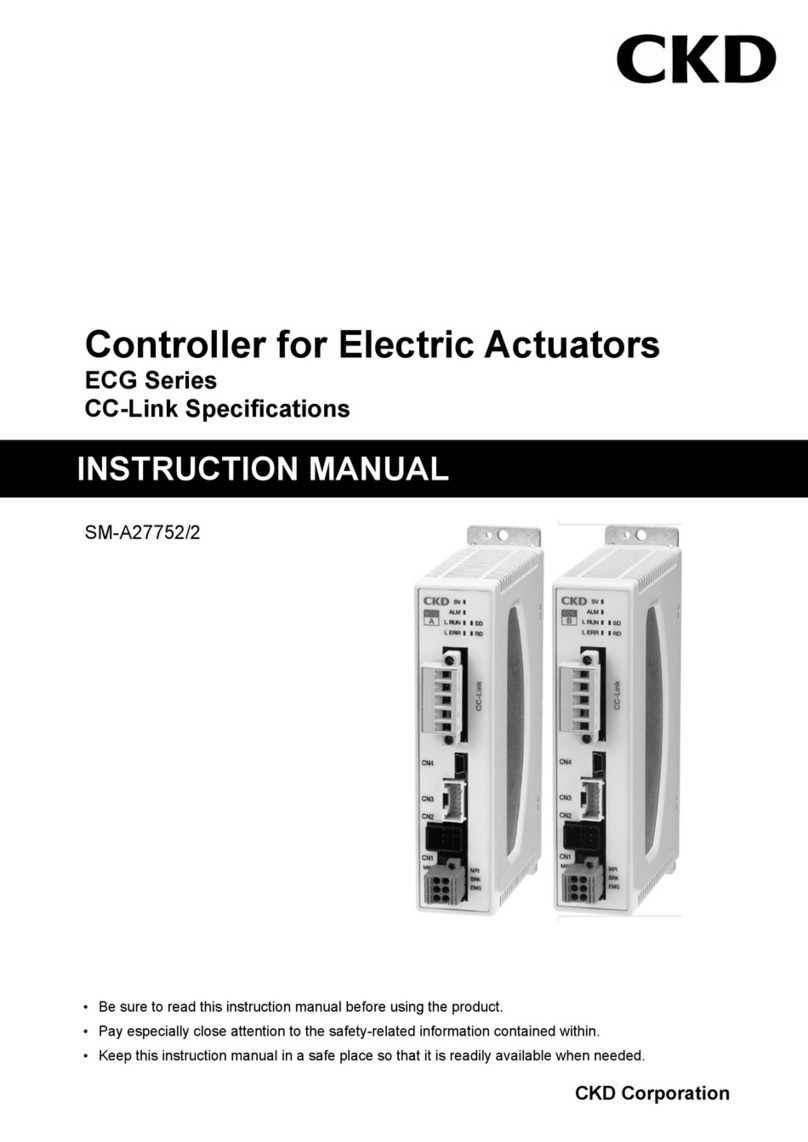
CKD AXD Series User manual

2023-09-22 SM-A61663-A/2
AXD SERIES
DRIVERFOR DIRECT DRIVE ACTUATOR
Parallel I/O Specifications
INSTRUCTION MANUAL
Before operating the product, read this instruction manual without fail.
Among all, carefully read the description related to safety.
Keep this instruction manual in a safe place so that you can read it at any time when necessary.

22023-09-22 SM-A61663-A/2
INTRODUCTION
Thank you for selecting our ABSODEX.
ABSODEX is a direct drive indexing unit developed to drive intermittently operated turntables or
the like of general industrial assembling machines and testing machines flexibly and accurately.
This instruction manual is exclusively for ABSODEX AXD Series. It is inapplicable to other
types.
If your use method or handling method is not appropriate, its functions cannot be performed
fully, an unexpected accident may occur and the product life may be shortened.
Before starting operation of our product, read through this instruction manual to keep the initial
performance and operate without failures.
The matters, specifications and appearance given in this instruction manual are subject to
change without notice.

32023-09-22 SM-A61663-A/2
FOR SAFETY OPERATION
When designing or manufacturing equipment incorporating this product, you are obligated to
manufacture safe equipment. To do so, check that the mechanism of the equipment and the
electric control for controlling the mechanism assure the safety of the system.
For safety of the design or management of the equipment, strictly observe the organization
standards and the regulations.
To operate our product safely, selection, operation and handling of the product, and adequate
maintenance procedures are important.
Be sure to observe the description given under WARNING and precautions to assure safety of
the equipment.
Various safety measures are taken for the product, however, handling that is not described in
this instruction manual could lead to an accident. Before using the product, read this instruction
manual carefully and gain full understanding of the contents.
To clearly indicate the degree of harm and damage and the possibility of their occurrence,
precautions are divided into three categories: “DANGER,” “WARNING,” and “CAUTION.”
DANGER
A case where if handling is wrong, it is assumed that an
imminent dangerous situation due to which a death or serious
injury may be caused will occur.
WARNING
A case where if handling is wrong, it is assumed that a
dangerous situation due to which a death or serious injury
may be caused will occur.
CAUTION A case where if handling is wrong, it is assumed that a risk
due to which an injury or physical damage may be caused will
occur.
Even items described under “CAUTION” may cause serious results.
Observe each item without fail because these safety precautions are important.

42023-09-22 SM-A61663-A/2
<Type of WARNING symbols>
A general mark that indicates
prohibited acts (what not to do).
A mark that prohibits the act of
touching the device.
A mark that prohibits the act of
inserting a finger.
A general mark that indicates the
danger of electric shock or burn.
A mark that indicates the danger
that occurs when an automated
device is activated.
A general mark that instructs what
you must do.
A mark that instructs you to
carefully read the instruction
manual.
A mark that instructs you to
connect a ground cable.

52023-09-22 SM-A61663-A/2
Precautions for the Product
DANGER
Do not attach or remove connectors with the power on.
A malfunction, failure, or electric shock may be caused.
Do not operate in explosive or fire atmosphere.
Do not use the product for the following purposes:
Medical appliances for maintaining or managing human life or body
Mechanism or machine equipment intended for travel or transportation of people
Important security parts of machine equipment
WARNING
Do not alter or additionally process the product.
Alteration or additional processing not only lead to the risk of fire or electric
shock but also to non-compliance with the specification described in the
instruction manual.
Do not handle the product, attach or remove devices until the safety is
confirmed.
Inspect or maintain machines or equipment after confirming that the safety of all
systems in which the product involves is ensured. Power off the equipment and
the applicable facilities, and be careful not to get electric shock.
Even after the operation stopped, there may be hot areas or energized parts. Be
careful when handling the product, or attaching or removing devices.

62023-09-22 SM-A61663-A/2
WARNING
A person with sufficient knowledge and experience should handle the
product.
The product is designed and manufactured as equipment/component for general
industrial machinery.
Observe the use of the product within the specification.
The products cannot be used out of its intrinsic specification.
As this product is intended for use in equipment/component for general industrial
machinery, the uses under the following conditions or environments are not
covered. If you consulted with our company for adoption and understood the
specification of our product, such use is covered. However, in such cases, take
safety measures to avoid dangers in case of failure.
◎Use in conditions or environments other than those specified in the
specification, or outside.
◎Use in nuke, railways, aviation, ships, vehicles, medical appliances, and
equipment or applications that come in direct contact with beverages, food,
etc.
◎Use in applications that require safety, such as entertainment devices,
emergency shut-off circuit, press machine, braking circuit, and safety
measures.
◎Use in applications where significant impact on people and property are
expected and safety is particularly required.
For safety related to equipment design, observe the organization standards,
law, etc.

72023-09-22 SM-A61663-A/2
CONTENTS
INTRODUCTION.................................................................................................... 2
FOR SAFETY OPERATION .................................................................................. 3
Precautions for the Product............................................................................................5
CONTENTS ........................................................................................................... 7
1. PRODUCT CONFIGURATION .............................................................. 12
System Configuration ..................................................................................12
Instruction Manual for the Product..........................................................14
2. OPERATION FLOW ................................................................................ 15
Installation and Connection Check ..........................................................17
Creation of Test Operation Program ........................................................19
Gain Adjustment ...........................................................................................20
Home Position Determination....................................................................26
Test Operation................................................................................................26
Wiring...............................................................................................................27
3. INSTALLATION ...................................................................................... 29
Driver Installation.........................................................................................31
About Cable ....................................................................................................33
Unpacking .......................................................................................................33
Wiring Method................................................................................................35

82023-09-22 SM-A61663-A/2
4. HOW TO USE .......................................................................................... 56
Pin Arrangement and Signal Name..........................................................57
How to Use General I/O Signals ...............................................................62
Pulse String Input Signals ..........................................................................82
Encoder Output Function ............................................................................86
Application Example of I/O Signal ...........................................................87
Operation Panel ...........................................................................................100
5. PARAMETER SETTING ....................................................................... 102
Parameters and Contents .........................................................................102
Types and Characteristics of Cam Curve...............................................116
Amount of Home Position Offset and Home Positioning Motion ...118
Precautions for Software Limit................................................................119
Judgment of In-position ...........................................................................121
Judgment of Positioning Completion.....................................................122
Correct Setting Of PRM16 (In-Position Range) ..................................123
G101 (Equal Segment Designation) and Parameter .........................125

92023-09-22 SM-A61663-A/2
Using Filters..................................................................................................129
Positioning Completion Signal Outputting Time.................................132
Controlled Stop upon Alarm Valid/Invalid ...........................................132
In-position Signal Output Mode..............................................................133
Mode Selection of I/O Signal ...................................................................133
Integral Limiter ...........................................................................................134
6. PROGRAM ............................................................................................. 135
General Description ....................................................................................135
Operation Mode ...........................................................................................137
NC Program Format....................................................................................138
Code List ........................................................................................................140
ABSODEX Status at Power-on Start.......................................................148
NC Program Example .................................................................................150
7. COMMUNICATION FUNCTIONS (CN1: USB)........................................ 154
Communication Codes ...............................................................................154
Communication Code List .........................................................................158
Communication Methods ..........................................................................163
8. GAIN ADJUSTMENT............................................................................ 164
What is Gain Adjustment? ........................................................................165
Gain Adjustment Method ..........................................................................167

10 2023-09-22 SM-A61663-A/2
9. APPLICATION EXAMPLES ................................................................. 174
Product Type Change .................................................................................174
Shortest Route Indexing...........................................................................176
Crimping ........................................................................................................179
Pick and Place (Oscillation)......................................................................181
Indexing Table .............................................................................................184
Continuous Rotation...................................................................................186
10. MAINTENANCE AND TROUBLESHOOTING ........................................ 188
Maintenance Inspection ............................................................................190
Troubleshooting...........................................................................................191
System Initializing ......................................................................................195
11. ALARMS ................................................................................................. 196
Alarm Display and Description ................................................................196
Servo Status for Alarms ............................................................................201
12. SUPPORT FOR UL STANDARD.......................................................... 202
Precautions for Using the Driver ............................................................203
13. SUPPORT FOR EUROPEAN STANDARDS........................................... 209
EU Directive / European Standards .......................................................209
Precautions on Operation in EU Member Countries and U. K.........210

11 2023-09-22 SM-A61663-A/2
Installation Method ....................................................................................215
14. TERMS OF WARRANTY ...................................................................... 218
15. REFERENCE INFORMATION ............................................................. 219
Driver Specifications ..................................................................................219

12 2023-09-22 SM-A61663-A/2
1. PRODUCT CONFIGURATION
System Configuration
BASIC SETTING ITEMS
NC programs are input at a PC.
Required parameters are input in the same way.
Gain is adequately set.
BASIC DRIVE METHODS
A program to be executed is selected at the PLC.
Start signal is input at the PLC.
System Configuration Example
<System Configuration>
Note 1: Do not connect the Dialog Terminal unless for programming, parameter entry or test operation.
ABSODEX Actuator
unit
(Encoder cable)
(Power cable)
Driver unit
I/O connector
PC
Safety
relay unit
Safety door
switch, etc.
PLC
Electromagnetic
contactor
Zero phase reactor
Noise filter
3 phases
200 VAC
Molded case
circuit breaker
Regenerative
resistor
Surge protector
Ground
Note 1
I/O
STO cable
USB cable (mini-B)

13 2023-09-22 SM-A61663-A/2
CAUTION
If a power cable noise filter is used, do not use a power line noise filter.
If other than the compatible driver is connected, the actuator may be burned.
If the main power is turned on while there is position deviation, the actuator
will rotate due to the function to clear the position deviation caused.
If the main power and control power are turned on separately, make sure that
ABSODEX is in servo-off state before turning on power.
When the control power is turned on again, a malfunction may be caused, so
turn it on again with the main power off or turn the main power and control power
on simultaneously again.
Route the power cables such as the power cable and power supply cable
separately from the signal cables such as the encoder cable and I/O cable.
Do not tie the cables belonging to different groups or do not route them in
the same conduit.
A wrong combination between the actuator and driver will cause alarm 3
when the power is turned on.
Check the combination between the actuator and driver.
For details of alarm 3, refer to “11. ALARMS.”
Main power and control power must branch off from one power supply
system; otherwise, the driver may breakdown.
To avoid accidents, install an over-current protective device in the main
power and control power (L1, L2, L3, L1C, and L2C).
When using a circuit breaker, select one that has high frequency counter
measures for inverter use.
List of Peripheral Devices
Components Product Name, Model Manufacturer
Product Driver AXD Series
CKD
Corporation
Optionally
available
Actuator AX1R Series
AX2R Series
AX4R Series
Power cable AXP-CBLM1-□□□
Encoder cable AXP-CBLE1-□□□
Free copy PC setup software AX-Tools Windows Version Note 1
Note 1: The software may not run in some environments.

14 2023-09-22 SM-A61663-A/2
Instruction Manual for the Product
This instruction manual is “SM-A61663.”
The instruction manuals related to this product are as follows:
AX1R Series
AX2R Series
AX4R Series
SM-A83981
Actuator
Setup software
SM-A63470
AX-Tools
AXD Series
Parallel I/O Specifications
SM-A61663
(This instruction manual)
AXD Series
CC-Link specifications
SM-A63468
AXD Series
EtherCAT specifications
EtherNet/IP specifications
SM-A63469
Driver

15 2023-09-22 SM-A61663-A/2
2. OPERATION FLOW
In this chapter, the purpose is to operate ABSODEX.
Functions are configured in the following way when the product is shipped from the factory.
Forced stop input (CN3-17) : Valid (I/O signal necessary; in case of no input, forced stop
(servo-off) 7-segment LED display 9.2.
Servo-on input (CN3-14) : Valid (I/O signal necessary; in case of no input, servo-off) 7-
segment LED display .. (dot)
When test operation is conducted without I/O cables connected, functions can be invalidated
temporarily, using the following communication commands.
To invalidate the forced stop input temporarily : L7M_23_2
To invalidate the servo-on input temporarily : L7M_52_999 (valid only in servo-off mode)
The state before change is restored after the control power is turned off then on again.
To invalidate the forced stop input temporarily, send the above-mentioned communication
command (L7M_23_2) and then perform alarm reset (send “S7”).
To invalidate the servo-on input temporarily, change to the servo-off mode first (by sending
“M5”), and then send the above-mentioned communication command (L7M_52_999).
Next, change to the automatic operation mode (by sending “M1”) and conduct test operation.
If you are not using the above functions, enter the following parameters.
Do not use the forced stop input: : L7_23_2
Do not use the servo-on input: : L7_52_1
The setting remains effective even after the control power is turned off then on again.
To invalidate the forced stop input, send the above-mentioned communication command
(L7_23_2) and then perform alarm reset (send “S7”) or turn the control power off then on
again.
Turn the control power off then on again to switch the servo-on input function.
After the function is switched, CN3-14 is assigned to program stop input.
The 7-segment LED shows
(a dr and a dot) at the third digit and the second digit
from the right without an alarm.
The 7-segment LED (1st digit from the right) shows the operation mode.
For servo off,
(dr and two dots) will be displayed.

16 2023-09-22 SM-A61663-A/2
2.3. Gain Adjustment
2.1. Installation and Connection Check
2.2. Creation of Test Operation Program
2.4. Home Position Determination
2.5. Test Operation
End
2.3.4. Manual Tuning2.3.1. Auto Tuning
Check if the ABSODEX is installed and
connected correctly.
Use the AX
-Tools to build a program easily.
Adjust to the gain matching the load.
Use the home position offset function to
determine the home position in an arbitrary
position. (This step may be skipped for test
operation.)
Supply a start input to start operation.
Follow the above procedure to perform test
operation.

17 2023-09-22 SM-A61663-A/2
Installation and Connection Check
Fix the ABSODEX unit securely.
The full performance of ABSODEX is not achieved with unstable installation or with a loose
base or stand. Install the load securely, too.
A loosely installed load or one with loose bolts will cause oscillation. For details, refer to “3.
INSTALLATION.”
Because the product is of a quick-response specification, the operation noise may be larger
than earlier types when operation is made at a small rigidity.
If you have problems with larger operation noises, install a vibration-preventive filter (PRM62
to PRM66).
<Unit Installation Example>
グラグラ
しないこと
ボルトは緩んでいないか
×
○
Make sure the bolts are
securely fastened.
Secure
installation

18 2023-09-22 SM-A61663-A/2
Next, connect all of the actuator, driver and power supply as well as peripheral devices.
For details, refer to “1. PRODUCT CONFIGURATION.”
<Connection Example>
ABSODEX Actuator
unit
(Power cable)
Molded case
circuit breaker
Noise filter
3 phases 200 VAC
Surge
protector
Ground
(Encoder cable)
Driver unit
Electromagnetic
contactor (optional)
Regenerative
resistor (optional)
Zero phase reactor
PC
The personal computer is required
for the test operation.

19 2023-09-22 SM-A61663-A/2
Creation of Test Operation Program
Gain adjustment is necessary for the operation of ABSODEX.
Gain adjustment is made for each load so that ABSODEX operates in the best state.
Create a four-segment program used for a gain adjustment and test operation using the AX-
Tools.
For details, refer to the “AX-Tools instruction manual.”
Each time this program runs, the actuator turns clockwise by an indexing angle of 90° in a
traveling time of 1 second.
After checking that there is no interfering matter when ABSODEX moves when the power is
turned on, turn the power on.
If ABSODEX is driven by a force, alarm 1 is caused.
Turn the power off then on again and check that the alarm light is unlit.
CAUTION
The coordinates of the actuator position are recognized when the power is
turned on. Be careful to avoid moving the output axis for several seconds
since the power is turned on.
If there is an external mechanical retention mechanism such as the brake,
stagger the retention mechanism resetting timing from the power-on timing.
If the output axis moves when the power is turned on, alarm F may be caused.

20 2023-09-22 SM-A61663-A/2
Gain Adjustment
WARNING
Keep hands away from the rotating part as sudden motion may take place
during gain adjustments or trial run.
Make sure of the safety in the full revolution of the actuator before turning it on to
adjust.
Make sure that the safety is assured to operate the actuator in case the unit
is operated from the place unable to confirm the motion.
CAUTION
The actuator may turn several turns during auto tuning.
Remove wiring, piping and other interfering matters to allow it to rotate.
If removal of any interfering matter is impossible, manually adjust the gain.
For manual tuning, refer to “8. GAIN ADJUSTMENT.”
If a work torque (external force to rotate the output axis of the actuator) acts
as shown in “Action of Work Torque” of “2.3.1. Auto Tuning.”
Use the manual gain adjustment method, too, in this case.
After checking that there is no interfering matter when ABSODEX moves
when the power is turned on, turn the power on.
If ABSODEX is driven by a force, alarm 1 is caused.
Turn the power off then on again and check that the alarm light is unlit.
After the auto tuning command is sent (by pressing the Enter key), auto
tuning begins. With this, the ABSODEX starts to oscillate.
Several rotations may be caused according to some loads. Remove wiring,
piping, and other interfering matters carefully before pressing the Enter key.
Table of contents
Other CKD Controllers manuals

CKD
CKD SM-A10616-A User manual

CKD
CKD EVD-1000 Series User manual

CKD
CKD LN Series User manual

CKD
CKD EVD-1000 Series User manual

CKD
CKD ERL2 Series User manual
CKD
CKD AX1000T Series User manual

CKD
CKD KBX-10E-U Series User manual

CKD
CKD FLCR-G Series User manual

CKD
CKD KBX-50 User manual

CKD
CKD FCM Series User manual
Popular Controllers manuals by other brands

Technische Alternative
Technische Alternative UVR610 General programming information, User manual

Moeller
Moeller easyControl EC4-200 installation instructions

Pichler
Pichler XQ+ 15 user manual

Mi-Light
Mi-Light MiBOXER FUT041 manual

PCS Electronics
PCS Electronics PEBBLE Quick setup guide

Vacon
Vacon 100 INDUSTRIAL Technical guide