Compleo ADVANCED IMS bm SAM User manual

Operating instructions
Compleo ADVANCED IMS bm SAM®
Compleo DUO IMS SAM®/
DUO fleet IMS SAM®
Article number: A11XCXXXXX
Issue: 2023-02
Revision: 02

2 A11XCXXXXX | 02 2023-02
1About this manual...............................................................................................4
1.1 Further requirements ................................................................................................................................4
1.2 Manufacturer and contact address.........................................................................................................5
1.3 Conventions of presentation ....................................................................................................................5
1.4 Abbreviations ...............................................................................................................................................6
2Safety..................................................................................................................7
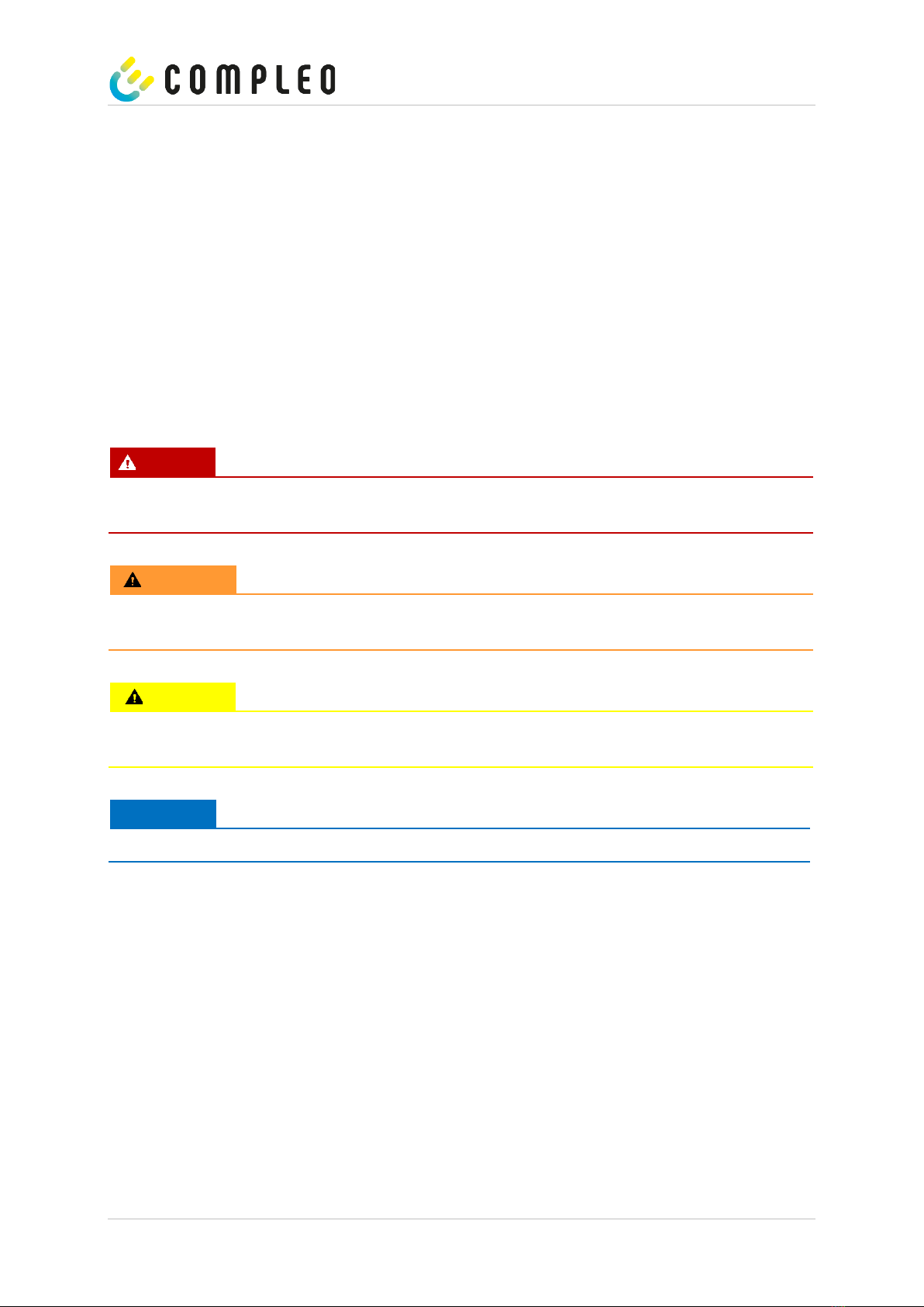
2.1 Warnings ....................................................................................................................................................... 7
2.1.1 Sectional warnings ................................................................................................................................8
2.2 Intended use ................................................................................................................................................8
2.3 Foreseeable misuse....................................................................................................................................8
2.4 Safety instructions for the user................................................................................................................8
2.5 Personnel qualification ..............................................................................................................................9
2.6 Dangers and residual risks....................................................................................................................... 10
2.6.1 Electrical voltage ................................................................................................................................. 10
2.6.2 Incorrect handling............................................................................................................................... 10
3Product description ..........................................................................................11
3.1 Design ........................................................................................................................................................... 11
3.2 Scope of delivery........................................................................................................................................12
3.3 Series label ................................................................................................................................................. 14
3.4 Technical specifications .......................................................................................................................... 15
3.5 General Functions and Scope of Application...................................................................................... 19
4Transport, packaging and storage....................................................................20
4.1 Transport Inspection ............................................................................................................................... 20
4.2 Storage conditions.....................................................................................................................................21
4.3 Safety Measures Before Use ....................................................................................................................21
5Installation........................................................................................................ 22
5.1 Location ......................................................................................................................................................22
5.2 Installation work ........................................................................................................................................22
5.3 Mechanical installation.............................................................................................................................23
5.3.1 Installation version BM with SMC base............................................................................................24
5.4 Housing closure: Double locking............................................................................................................ 27
5.5 Electrical installation ................................................................................................................................28
5.6 Connecting the supply line......................................................................................................................29
5.7 Data connection cable ............................................................................................................................. 31
5.7.1 RJ45 connector ...................................................................................................................................33
6Commissioning .................................................................................................35
6.1 Testing the charging system ...................................................................................................................36

2023-02 A11XCXXXXX | 02 3
6.2 System start-up .........................................................................................................................................36
6.3 Configuration of the charging system with Compleo DUCTO..........................................................38
6.3.1 Creating a network connection........................................................................................................38
6.3.2 Calling up the configuration interface ........................................................................................... 40
6.3.3 Operator login..................................................................................................................................... 40
6.3.4 Changing parameters ......................................................................................................................... 41
6.3.5 Log in as electrician ........................................................................................................................... 43
7Operation .........................................................................................................48
7.1.1 Meaning of the status LED colours ................................................................................................. 50
7.1.2 Authorisation at the RFID field ......................................................................................................... 51
7.1.3 Authorisation at the credit card terminal ...................................................................................... 51
7.1.4 Connecting the charging cable ........................................................................................................52
7.1.5 Starting the charging process...........................................................................................................52
7.1.6 End charging process with RFID field..............................................................................................53
7.1.7 End charging process with credit card terminal...........................................................................53
7.1.8 Disconnecting the charging cable....................................................................................................54
7.1.9 Retrieve billing data ............................................................................................................................54
8Malfunctions .....................................................................................................55
8.1 Residual current circuit breaker (RCCB)..............................................................................................55
8.2 Residual current circuit breaker (RCCB)..............................................................................................55
9Error display and measures..............................................................................56
9.1 About this advices.....................................................................................................................................56
9.1.1 Field of application .............................................................................................................................56
9.2 OCPP 1.6......................................................................................................................................................56
9.3 Compleo-specific .....................................................................................................................................58
10 Maintenance .....................................................................................................62
10.1 Maintenance plan ......................................................................................................................................63
10.2 Maintenance and repair...........................................................................................................................63
10.3 Cleaning ......................................................................................................................................................65
11 Decommissioning, dismantling and disposal....................................................66
12 Memory and display module SAM.....................................................................67
13 Index .................................................................................................................68
14 Annexes ............................................................................................................69
14.1 Housing dimensions..................................................................................................................................69
14.2 Commissioning and test report for AC charging systems..................................................................71
14.3 EU Declaration of Conformity ................................................................................................................75
15 Ducto Quick Guide ...........................................................................................78

4 A11XCXXXXX | 02 2023-02
1About this manual
This manual contains descriptions and important information for the safe and trouble-free use of the
charging system. The manual is part of the charging system and must be accessible at all times to all
persons working on and with the charging system. The manual must be kept in a clearly legible
condition.
The personnel must have carefully read and understood this manual before starting any work. The
basic prerequisite for safe working is the observance of all specified safety and warning instructions as
well as handling instructions in this manual.
In addition to the instructions in this manual, the local accident prevention regulations and the national
industrial safety regulations apply.
Illustrations are for basic understanding and may differ from the actual design of the charging system.
1.1 Further requirements
A warranty with regard to function and safety is only given if this manual is observed. Compleo
Charging Solutions AG is not liable for personal injury or damage to property caused by failure to
observe the operating instructions.
The manufacturer of the charging system is not liable for consequential damage. The operator must
ensure that the charging system is properly installed and used as intended.
During installation and start-up, the national legal requirements and regulations for accident
prevention must be observed. In Germany these include the requirements according to DIN VDE 0100
and the accident prevention regulations according to DGUV V3.
Before the system is released, an appropriate test must be carried out to safeguard all safety features
and proper functionality of the charging system. Furthermore, the operator must ensure the
operational safety of the charging system through regular maintenance.
Compleo Charging Solutions GmbH assumes no liability for errors within these operating instructions.
This document reflects the state-of-the-art of the product at the time of publication. The contents of
this document are for information purposes only and are not the subject of a contract.
ATTENTION
A list of the normative references and regulations according to which the charging system was
designed and constructed can be found in the declaration of conformity. When installing and
commissioning a charging system from Compleo Charging Solutions, nationally applicable standards
and regulations must also be observed.
NOTE
All standards, regulations, test intervals and the like mentioned in this document are valid in
Germany. If a charging system is set up in another country, equivalent documents with a national
reference must be used.

2023-02 A11XCXXXXX | 02 5
1.2 Manufacturer and contact address
Compleo Charging Solutions AG
Oberste-Wilms-Straße 15a
44309 Dortmund, Germany
Tel.: +49 231 534 923 - 777
Fax: +49 231 534 923 - 790
e-mail address: info@compleo-cs.com
1.3 Conventions of presentation
For easy and quick understanding, different information in this manual is presented or highlighted as
follows:
•List without fixed order
•List (next item)
–Subitem
–Subitem
1. Handling instruction (step) 1
2. Handling instruction (step) 2
–Additional notes for the previous step
1 Position number in figures and legends
2 Consecutive position number
3 …
List/check point
List/next check point
Reference (example): See "chapter 6.5, page 27"
NOTE
A note contains application tips and useful information, but no warnings of hazards.

6 A11XCXXXXX | 02 2023-02
1.4 Abbreviations
Abbreviation
Explanation
AC
Alternating Current
DC
Direct Current
EMC
Electromagnetic Compatibility
EVSEID
Electric Vehicle Supply Equipment ID
HMI
Human-Machine Interface
ID
Identification Number
IR
Infrared
kWh
Kilowatt hour
LCD
Liquid Crystal Display
LS
Charging system/charging station
MCB
Miniature Circuit Breaker
MessEG
Measuring and calibration law
MessEV
Measuring and calibration regulations
N/A
Not Available/Applicable
OCPP
Open Charge Point Protocol
PSU
Power Supply Unit
RCD
Residual Current Device
RDC-DD
Residual Direct Current-Detecting Device
RTC
Real-Time Clock
S/N
Serial number
SAM
Memory and display module
SPD
Surge Protective Devices
SW
Software
UV
Sub-distribution
VNB
Distribution system operator

2023-02 A11XCXXXXX | 02 7
2Safety
In order to ensure operational safety of the charging equipment and to avoid serious injuries caused by
flashovers or short circuits, the following information and safety instructions for operating the unit
must be observed. Repair work on the unit must only be carried out by authorised specialist personnel.
The housing of the unit may only be opened by persons who have been properly instructed. The
following points therefore apply:
•Read and observe safety and warning instructions
•Read and follow instructions
2.1 Warnings
In this manual, warnings and notes are presented as follows.
DANGER
Indicates an imminent danger that will result in death or serious injury if not avoided. There is great
danger to life.
WARNING
Indicates a potentially hazardous situation which, if not avoided, could result in death or serious
injury.
CAUTION
Indicates a potentially hazardous situation which, if not avoided, may result in minor or moderate
injury.
ATTENTION
Indicates a potentially hazardous situation which, if not avoided, may result in property damage.

8 A11XCXXXXX | 02 2023-02
2.1.1 Sectional warnings
Sectional warnings refer to entire chapters, a section or several paragraphs within this manual.
Sectional warnings are presented as follows (example warning):
WARNING
Type and source of the danger.
Possible consequences if the danger is not observed.
•Measures to avoid the danger.
2.2 Intended use
The charging system is intended exclusively for charging electric vehicles.
The charging system is suitable for public and semi-public areas and can be used indoors and
outdoors.
The charging system is intended exclusively for stationary installation.
Any use beyond this is considered improper use. The manufacturer is not liable for damages resulting
from this.
2.3 Foreseeable misuse
The use of the charging system as a power source for other power consumers is not in accordance
with its intended use and is considered misuse.
Only charging cables of type 2/ 20 A or only charging cables of type 2/ 32 A may be used on charging
systems equipped with a charging socket type 2. Charging cables that deviate from this are not
accepted by the systems.
Charging systems may only be connected to the power supply via a fixed and non-separable supply
line.
2.4 Safety instructions for the user
This charging system may only be used in the manner described in this manual. If the charging system is
used for other purposes, the operator may be endangered and the charging equipment may be
damaged. This manual must always be accessible. Note the following points:
•If no charging process is active, anchor any existing charging cables on the charging system in
the brackets provided or wrap them around the housing of the charging system.
•The distance between a charging system and a vehicle must not exceed 3 metres.
•The charging system may only be operated when completely closed. Do not remove covers
inside the charging system.

2023-02 A11XCXXXXX | 02 9
2.5 Personnel qualification
Qualified and trained electricians meet the following requirements:
•Knowledge of general and special safety and accident prevention regulations.
•Knowledge of the relevant electrical engineering regulations.
•Product-specific knowledge through appropriate training.
•Ability to identify hazards associated with electricity.
DANGER
Danger due to electric current
Touching live parts will result in electric shock with serious injury or death.
•Work on electrical components may only be carried out by a qualified electrician and in
accordance with electrical engineering rules.
•Ensure they are de-energised and take suitable protective measures.

10 A11XCXXXXX | 02 2023-02
2.6 Dangers and residual risks
NOTE
Compleo charging systems as a whole do not contain SVHCs (Substances of Very High Concern) in a
concentration of more than 0.1 % (w/w), related to the individual charging station. However,
individual components may contain SVHCs in concentrations > 0.1 % (w/w).
•When the charging stations are used as intended, no SVHCs are released and there are no
risks to humans or the environment.
2.6.1 Electrical voltage
Dangerous electrical voltages may be present inside the housing of the charging system after the
housing has been opened. There is a danger to life if contact is made with live components. Serious
injury or death is the result.
•Work on electrical equipment may only be carried out by a qualified electrician and in
accordance with electrical engineering rules.
•Disconnect the charging system from the power supply.
•- The system has life-threatening DC voltages, which only disappear after five minutes after
switching off due to capacitor charges. A corresponding period of five minutes must elapse
before working on exposed parts.
2.6.2 Incorrect handling
•Pulling on the charging cable can lead to cable breakage and damage. Only pull the charging
cable out of the socket directly at the plug.
•The use of extension cables is not permitted. To avoid the risk of electric shock or cable fire,
only one charging cable may be used at a time to connect the electric vehicle and charging
system.
•A charging system whose charging cables are in contact with the ground involves a risk of
tripping or mechanical damage if run over. The operator of the charging system must implement
appropriate measures for cable routing and affix appropriate warnings.

2023-02 A11XCXXXXX | 02 11
3Product description
The charging system described below is suitable for charging electric vehicles indoors and outdoors
with installation on solid ground.
The operation of the charging system is designed to give clear and easily understandable instructions,
statuses and messages, which can be indicated to the user by means of status LEDs and displays.
3.1 Design
1 Cover (roof)
2 SAM display and storage module
3 Charger interface, socket type 2
4 Door with locking mechanism
5 Credit card terminal
alternative: RFID reader
6 Information display
Fig. 1: Charging system (illustration similar)
1
2
6
4
5
3

12 A11XCXXXXX | 02 2023-02
3.2 Scope of delivery
The scope of delivery of the Compleo DUO IMS SAM®/ Compleo DUO fleet IMS SAM® (Compleo ADVANCED
IMS SAM®) includes, in addition to the charging column, the following features and components:
Authentication
•Credit card terminal (payment with credit
card, charging current or website)
•RFID reader (optional)
(optional)
Authentication:
RFID tag & RFID card (optional)
(optional)
Charging interfaces:
AO2 (socket with sliding cover type 2) alt.
HC2 (spiral cable type 2) alt.
(alternative)
Status displays and/or display:
Status LED
3-colour
SAM or counter with viewing window:
Memory and display module alt.
Counter with digital display
(alternative)
Foundation:
Asphalt & concrete (BM) alt.
Concrete base (BM)
(alternative)
Housing closure:
Pivoted lever

2023-02 A11XCXXXXX | 02 13
Documentation:
Circuit diagram
Operating instructions including design
drawings
Installation accessories (optional):
Base filler
Installation material
(optional)
(optional)
Surge protection (optional):
Surge arrester
(optional)

14 A11XCXXXXX | 02 2023-02
3.3 Series label
The charging systems from Compleo Charging Solutions AG can be identified by an individual serial number. A
series label is attached inside the charging system. The following illustration shows an example of a series label:
Illustration similar
The following information can be identified by means of the serial label:
(1) Name of the manufacturer
(2) Address/ Service number/ Website of the manufacturer
(3) Type/ Installation type/ Charging interfaces/ Charging capacities of charging system
(4) Material number or article number of the charging system
(5) Serial number of the charging system
(6) Input: Number of phases x voltage frequency input current
(7) Ambient temperature
(8) Output AC: Voltage, max. current
(9) Calendar week and year of manufacture
(10) Output DC: Voltage range, max. current
(11) Protection type and protection class of the charging system Pictogram (safety information)
(12) Number of the type examination certificate
(13) Accuracy class of the measuring instrument according to EN 50470
(14) Pictogram (protection class, disposal, operating and maintenance instructions)
(15) Metrology marking

2023-02 A11XCXXXXX | 02 15
3.4 Technical specifications
The following table is an excerpt from the standard portfolio of Compleo Charging Solutions AG charging systems.
A purchased charging system may deviate from this list according to customer-specific wishes and requirements.
If changes have been made to a standard product, the modified charging system is identified with a separate
table of technical specifications in the Annex.
Charging system
DUO bm IMS/ DUO fleet bm IMS (ADVANCED bm IMS)
Charging mode
Mode 3/ IEC 61851
Charging interfaces
2 x type 2 socket with sliding cover
Mains connection
Mains connection
HAK for NH fuses
Data line
Cable connection
Min. connection cross-
section
26 AWG
Max. length
30 m
Electrical characteristics
Charging interface(s)
Type 2 socket with sliding cover
Max. rated current
32 A/ 3~
63 A/ 3~
Nominal voltage
400 V/ 3~
400 V/ 3~
Mains frequency
50 Hz
50 Hz
Network form
TT/ TN
TT/ TN
Protection class
II
II
Overvoltage category
III
III
Charging voltage
400 V/ 3~
400 V/ 3~
Max. charging capacity
per loading point
11 kW
22 kW
Charging current
16 A/ 3~
32 A/ 3~
Protective devices

16 A11XCXXXXX | 02 2023-02
RCD
RCCB: 40 A/0.03 A, type A;
RDC-DD: 6 mA
RCCB: 40 A/0.03 A, type B
MCB
2 x C20A,
1 x B10A
2 x C40A,
1 x B10A

2023-02 A11XCXXXXX | 02 17
Ambient conditions
Ambient temperature
-25 °C to +40 °C
Operating temperature (∅24
h)
≤ 35 °C
Storage temperature
-25 °C to +50 °C
Relative humidity
≤ 95 % (non-condensing)
Altitude
≤ 2000 m above sea level
Mechanical data
Dimensions (H x W x D)
BM: 1483 x 590 x 330 (H x W x D)
Max. weight
BM: 72 –80 kg (approximate depending on capacity and condition of
the equipment)
Housing
Sheet Moulding Compound (SMC)/ glass fibre reinforced polyester
Housing closure
Pivoted lever mechanism for locking cylinder
(single lock)
Protection type
IP44
Degree of contamination
3
Type/mounting
Base mounting
Communication interfaces
Data communication
TCP/IP
Data connection
LTE modem
(frequency/ transmission power)
(800 MHz, 900 MHz, 1800 MHz, 2100 MHz, 2600 MHz/ 23.0 ±1 dBm)
Backend communication
OCPP: 1.6J
RFID standard
Mifare Desfire,
Mifare Classic;
(frequency/ transmission power)
(13.56 MHz/ 13.9 mW,11.4 dBm) (125 kHz; 134.2 kHz/ 26 mW, 14.1 dBm)

18 A11XCXXXXX | 02 2023-02
Legal regulations
2014/53/EU (Radio Equipment Directive)
2011/65/EU (RoHS Directive)
2001/95/EG (Directive on General Product Safety)
2012/19/EU (WEEE Directive)
(EU) 2019/1021 (EU-POP Ordinance)
(EU) 1907/2006 (REACH Regulation)
SVHC
EU no.
CAS no.
Lead (Pb)
231-100-4
7439-92-1
4,4'-isopropylidenediphenol
(bisphenol A; BPA)
201-245-8
80-05-7

2023-02 A11XCXXXXX | 02 19
3.5 General Functions and Scope of Application
The compleo® Advanced IMS charging system from Compleo Charging Solutions AG has the functionality for
mode 3 charging. It is produced in different versions and has a practical housing that makes it possible to mount
it on solid ground using a simple installation method. The charging system has two charging points where parallel
charging is possible. The type of charging interface is safely constructed and easy to handle by means of a sliding
cover.
For “BM” type installation, the charging system is fixed by means of a practical and stable SMC base in the ground
surrounding the charging system. The base, which is precisely adapted to the housing, enables quick installation.
The charging system is produced in different performance classes and is therefore able to carry out reliable and
fast charging processes on vehicles. Depending on the product class and scope, the charging systems are
suitable for use in public and semi-public areas. In general, all charging systems from Compleo Charging
Solutions AG can be used indoors and outdoors.
The charging system has different displays which are embedded in the housing. The display options include a
reliable and easy to understand status LED. Different states, such as an ongoing charging process or state change,
and the transition from successful authorisation to the charging process, are easily recognisable by means of this
RBG LED. The meter reading of a charging point can be quickly captured and read from an appropriately recessed
window on the housing. Depending on the product class and scope, the charging systems are suitable for use in
public and semi-public areas. In general, all charging systems from Compleo Charging Solutions AG can be used
indoors and outdoors.
The compleo® Advanced IMS charging system incorporates state-of-the-art protection technology that ensures
maximum safety for the charging system and persons operating it.

20 A11XCXXXXX | 02 2023-02
4Transport, packaging and storage
4.1 Transport Inspection
Depending on the type and product scope of the charging system, it is delivered either upright or
horizontally in appropriate transport and protective packaging. Depending on the type of charging
system, air-cushioned protective films and/or cardboard boxes are used. The materials can also be
used as underlay during subsequent assembly.
1. After unpacking, thoroughly inspect the charging system for transport damage.
2. Compare the serial number of the charging system with that of the delivery documents to
exclude faulty deliveries.
3. Check delivery according to purchase and scope of delivery for completeness.
4. Proceed as follows in case of deviations or recognisable damages:
–Do not accept delivery or only accept it conditionally.
–Complaints must be reported immediately to the manufacturer in writing.
NOTE
We recommend to keep and reuse the original packaging for further transportation. Otherwise, the
packaging material must be disposed of in accordance with the applicable local regulations.
This manual suits for next models
2
Table of contents
Other Compleo Batteries Charger manuals

Compleo
Compleo GO User manual

Compleo
Compleo SOLO smart User manual

Compleo
Compleo Cito BM 500 User manual

Compleo
Compleo eBOX professional User manual

Compleo
Compleo SOLO N+ User manual

Compleo
Compleo eBOX smart User manual

Compleo
Compleo DUO bm User manual

Compleo
Compleo ECO s User manual

Compleo
Compleo eCLICK User manual

Compleo
Compleo eBOX professional User manual