Copyright © 2022 congatec AG HEVAm100 8/54
Contents
1 Introduction ............................................................................. 10
1.1 COM-HPC®Concept ............................................................... 10
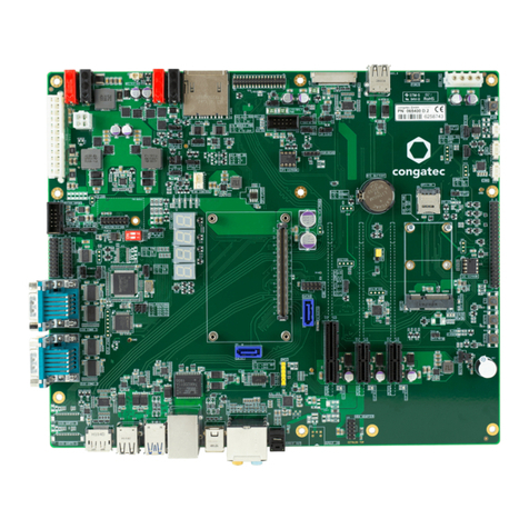
1.2 conga-HPC/EVAL-Server ......................................................... 10
1.2.1 Order Information.................................................................... 11
2 Connector Layout .................................................................... 12
3 Specifications........................................................................... 13
3.1 Feature List .............................................................................. 13
3.2 Mechanical Dimensions ........................................................... 14
3.3 Supply Voltage Power.............................................................. 14
3.4 Environmental Specifications................................................... 14
4 Connector Description............................................................. 15
4.1 Power Supply Connectors........................................................ 21
4.1.1 ATX Power Connector.............................................................. 21
4.1.2 EPS Power Connector.............................................................. 23
4.1.3 DC Banana Jack....................................................................... 23
4.1.4 Status LEDs .............................................................................. 24
4.1.5 VIN_PWR_OK Signal................................................................ 25
4.1.6 Power-Up Control .................................................................... 25
4.1.7 Module Type Detection ........................................................... 25
4.1.8 CMOS Battery Connector........................................................ 26
4.2 Extension Slots ........................................................................ 27
4.2.1 PCIe x16 Slot............................................................................ 28
4.2.2 PCIe x8 Slot.............................................................................. 28
4.2.3 PCIe x4 Slot.............................................................................. 29
4.2.4 M.2 Key M Socket.................................................................... 29
4.2.5 Board to Board Connector....................................................... 30
4.3 DisplayPort............................................................................... 31
4.4 UART........................................................................................ 32
4.4.1 BMC UART............................................................................... 32
4.4.2 Module UART .......................................................................... 33
4.5 USB Connectors....................................................................... 35
4.5.1 USB 3.1 Type-A ........................................................................ 35
4.5.2 Dual-stacked USB 3.1 Type-A .................................................. 36
4.5.3 USB 2.0 Headers...................................................................... 36
4.6 SATA ........................................................................................ 37
4.6.1 SATA Power ............................................................................. 37
4.6.2 Disk Drive Power Connector.................................................... 37
4.7 Ethernet Connectors................................................................ 38
4.7.1 RJ45-BMC Management Interface........................................... 38
4.7.2 RJ45 (10 Gb NBASE-T) ............................................................ 39
4.7.3 Mezzaline Card Connector ...................................................... 39
4.8 System Fan Headers ................................................................ 40
4.8.1 BMC System Fan...................................................................... 40
4.8.2 Module System Fan ................................................................. 41
4.9 eSPI Header ............................................................................. 42
4.10 I2C Header............................................................................... 43
4.10.1 I2C0 Header............................................................................. 43
4.10.2 I2C0 I/O Expander Header ...................................................... 44
4.10.3 I2C1 Pin Header....................................................................... 44
4.11 SMBus Header ......................................................................... 45
4.12 GPIO Header ........................................................................... 45
4.13 Front Panel Header.................................................................. 46
4.14 Intel ISP Adaptor-C2 Connector .............................................. 46
4.15 General Purpose SPI Header ................................................... 47
4.16 SPI Flash Socket....................................................................... 48
4.17 Feature Connector................................................................... 49
5 BMC Overview......................................................................... 50
5.1 Firmware .................................................................................. 50
6 Additional Features.................................................................. 52
6.1 Buttons..................................................................................... 52
6.1.1 Power....................................................................................... 52
6.1.2 Reset ........................................................................................ 52
6.2 Ground Test Points................................................................... 52
6.3 Debug Display ......................................................................... 53
7 Mechanical Dimensions ........................................................... 54
