manuals.online logo
Brands
  1. Home
  2. •
  3. Brands
  4. •
  5. Connects2
  6. •
  7. Automobile Accessories
  8. •
  9. Connects2 CTSJD001.2 User manual

Connects2 CTSJD001.2 User manual

Other Connects2 Automobile Accessories manuals

Connects2 CTSMT011.2 User manual

Connects2

Connects2 CTSMT011.2 User manual

Connects2 CT23AU13/L User manual

Connects2

Connects2 CT23AU13/L User manual

Connects2 CAM-BM1-AD User manual

Connects2

Connects2 CAM-BM1-AD User manual

Connects2 CT23DG06 User manual

Connects2

Connects2 CT23DG06 User manual

Connects2 CTQIAU03 Operation manual

Connects2

Connects2 CTQIAU03 Operation manual

Connects2 CAN-Connect CANHBJP1 User manual

Connects2

Connects2 CAN-Connect CANHBJP1 User manual

Connects2 Vision CAM-VW15 User manual

Connects2

Connects2 Vision CAM-VW15 User manual

Connects2 CAN-Connect CANHBBM2 User manual

Connects2

Connects2 CAN-Connect CANHBBM2 User manual

Connects2 CTUPO01 User manual

Connects2

Connects2 CTUPO01 User manual

Connects2 CTULR04 User manual

Connects2

Connects2 CTULR04 User manual

Connects2 CAM-MB2-AD User manual

Connects2

Connects2 CAM-MB2-AD User manual

Connects2 43uft03 User manual

Connects2

Connects2 43uft03 User manual

Connects2 CT51-MC03 User manual

Connects2

Connects2 CT51-MC03 User manual

Connects2 CAM-56 User manual

Connects2

Connects2 CAM-56 User manual

Connects2 Vision CAM-26 User manual

Connects2

Connects2 Vision CAM-26 User manual

Connects2 Vision CAM-17 User manual

Connects2

Connects2 Vision CAM-17 User manual

Connects2 CTSBM011.2 User manual

Connects2

Connects2 CTSBM011.2 User manual

Connects2 CT23MB26L User manual

Connects2

Connects2 CT23MB26L User manual

Connects2 CTKHA02 User manual

Connects2

Connects2 CTKHA02 User manual

Connects2 CT23AU12/L User manual

Connects2

Connects2 CT23AU12/L User manual

Connects2 CT23MB25/L User manual

Connects2

Connects2 CT23MB25/L User manual

Connects2 CTUJP01 User manual

Connects2

Connects2 CTUJP01 User manual

Connects2 CAM-55 User manual

Connects2

Connects2 CAM-55 User manual

Connects2 CTKIV02 User manual

Connects2

Connects2 CTKIV02 User manual

Popular Automobile Accessories manuals by other brands

Magneti Marelli AC161 Installation instruction

Magneti Marelli

Magneti Marelli AC161 Installation instruction

FDI uEZ GUI Start here

FDI

FDI uEZ GUI Start here

JCROffroad JT Install instructions

JCROffroad

JCROffroad JT Install instructions

Rostra VOXXElectronics 250-1930 owner's guide

Rostra

Rostra VOXXElectronics 250-1930 owner's guide

TOP VEHICLE TECH GR3FORD5 installation manual

TOP VEHICLE TECH

TOP VEHICLE TECH GR3FORD5 installation manual

Safe Fleet PRIME DESIGN AR-2000-BLK manual

Safe Fleet

Safe Fleet PRIME DESIGN AR-2000-BLK manual

Skoda Fabia Combi 5J Fitting instructions

Skoda

Skoda Fabia Combi 5J Fitting instructions

Camcar 40077 Al Mounting instructions

Camcar

Camcar 40077 Al Mounting instructions

Camcar 40089 AL Mounting instructions

Camcar

Camcar 40089 AL Mounting instructions

Impac Tradesman 2000 installation manual

Impac

Impac Tradesman 2000 installation manual

DVB OFFROAD BRSB-01 installation manual

DVB

DVB OFFROAD BRSB-01 installation manual

Safari Snorkel SS385HF installation guide

Safari Snorkel

Safari Snorkel SS385HF installation guide

ULTIMATE SPEED 279746 Assembly and Safety Advice

ULTIMATE SPEED

ULTIMATE SPEED 279746 Assembly and Safety Advice

SSV Works DF-F65 manual

SSV Works

SSV Works DF-F65 manual

ULTIMATE SPEED CARBON Assembly and Safety Advice

ULTIMATE SPEED

ULTIMATE SPEED CARBON Assembly and Safety Advice

Witter F174 Fitting instructions

Witter

Witter F174 Fitting instructions

WeatherTech No-Drill installation instructions

WeatherTech

WeatherTech No-Drill installation instructions

TAUBENREUTHER 1-336050 Installation instruction

TAUBENREUTHER

TAUBENREUTHER 1-336050 Installation instruction

manuals.online logo
manuals.online logoBrands
  • About & Mission
  • Contact us
  • Privacy Policy
  • Terms and Conditions

Copyright 2025 Manuals.Online. All Rights Reserved.

CTSJD001.2
Steering Wheel Control
Interface for John Deere Vehicles
APPLICATION
FEATURES
John Deere 6R Series
• Retains Steering Wheel Control Functionality
• Retains USB Input
• Retains AUX Input
• Retains & Amplies Original FM Antenna
• Retains OEM Screen (select functionality only)
• Updatable via USB (contact supplier for more information)
The information provided in this document is subject to change without notice due to manufacturer changes and/or improvements to the product/s. This
instruction manual is based on documented data and research. The manufacturer of this product cannot be held responsible for any changes made to the
vehicle by the manufacturer or damages that may occur through the installation of this product in accordance with the steps outlined herein.
Note: Application data is subject to change at any time
DISCLAIMER
CTSJD001.2_IG_en-GB_v1
i. Interface Box
ii. ISO Connector (16 Pin)
iii. Mini ISO Connector
iv. USB Male/Female Connectors
v. 3.5mm Jack Connector
vi. DAB Splitter
i
ii
iv
iii
v
vi
2CTSJD001.2_IG_en-GB_v1
PRIOR TO INSTALLATION
Read the manual prior to installation. Technical knowledge is necessary for installation. The place of installation
must be free of moisture and away from heat sources. Please ensure that the correct tools are using during the
installation to avoid damage to the vehicle or product. Connects2 can not be held responsible for the installation
of this product.
IN WIRING HARNESS
Purple Right Rear Speaker +
Purple/Black Right Rear Speaker -
Green Left Rear Speaker +
Green/Black Left Rear Speaker -
Grey Right Front Speaker +
Grey/Black Right Front Speaker -
White Left Front Speaker +
White/Black Left Front Speaker -
ADDITIONAL CONNECTIONS
See Wiring Diagram (Pg. 4) for information on where to connect
USB Retention Lead Retains OEM USB Input
3.5mm Jack Retains OEM AUX Input
DAB Splitter Retains/Amplies OEM Antenna
WIRING KEY
STEERING WHEEL CONTROL FUNCTIONALITY
The following diagram, though based on careful research, is an example only
Individual steering wheel control congurations may differ.
Yellow Permanent 12V
Black Ground
Red Ignition 12V
Orange Illumination
1. Volume +
2. Volume -
3. Mute
4. Track +
5. Track -
SRC
3
4
5
2
1
3
Need help? Visit support.connects2.com/tickets/technical
CTSJD001.2_IG_en-GB_v1
INSTALLATION GUIDE
Before installing the interface, the factory stereo must be removed and disconnected. To do this, please consult
the vehicle owner’s manual/handbook or contact a tting professional.
A stereo connection (patch) lead is also required for the installation of this interface (supplied separately).
Please ensure that you have the correct lead before proceeding. For universal patch leads, prepare the wiring
loops in accordance with the instruction manual supplied with the product before installation.
1. Connect the 12 Pin connector from the stereo connection (patch) lead to the interface box
2. Connect the opposite end of the stereo connection (patch) lead to the steering wheel control input on
the back of the aftermarket stereo
NOTE: This may be a 3.5mm jack connector or a wired input depending on the brand of aftermarket stereo being
tted. Please consult the aftermarket stereo installation manual for further information on where to make the
connection
IMPORTANT: THIS STEP MUST BE COMPLETED BEFORE CONNECTING POWER TO THE INTERFACE.
FAILURE TO DO SO MAY RESULT IN A LACK OF FUNCTIONALITY AND THE NEED TO REINSTALL THE
PRODUCT
!
3. Connect the 14 Pin connector from the supplied wiring loom to the interface box
4. Connect the power/speaker ISO connector to the power/speaker ISO connector from the
aftermarket stereo.
NOTE: For aftermarket stereos which do not have an ISO connector, please see “Wiring Key” on Pg.2 for informa-
tion on which wires to connect.
5. Connect the Mini ISO connector on the supplied harness to the Mini ISO connector from the vehicle.
8. Test stereo and steering wheel control functionality for correct operation before reassembling the
vehicle dashboard. If steering wheel control functions are unresponsive, please uninstall the interface and
wiring and reinstall carefully in accordance with the above steps.
6. Connect the 3.5mm Jack connector to the back of the aftermarket stereo to retain the vehicle’s factory
Aux input (if vehicle is equipped). Connect the USB Retention Lead to the vehicle’s original USB connection
and to the back of the aftermarket stereo to retain the vehicle’s factory USB input (if equipped)
7. To retain the vehicle’s existing FM antenna for use with the aftermarket stereo to receive DAB services,
connect the DAB splitter to the vehicle and stereo as outlined on Pg. 4.
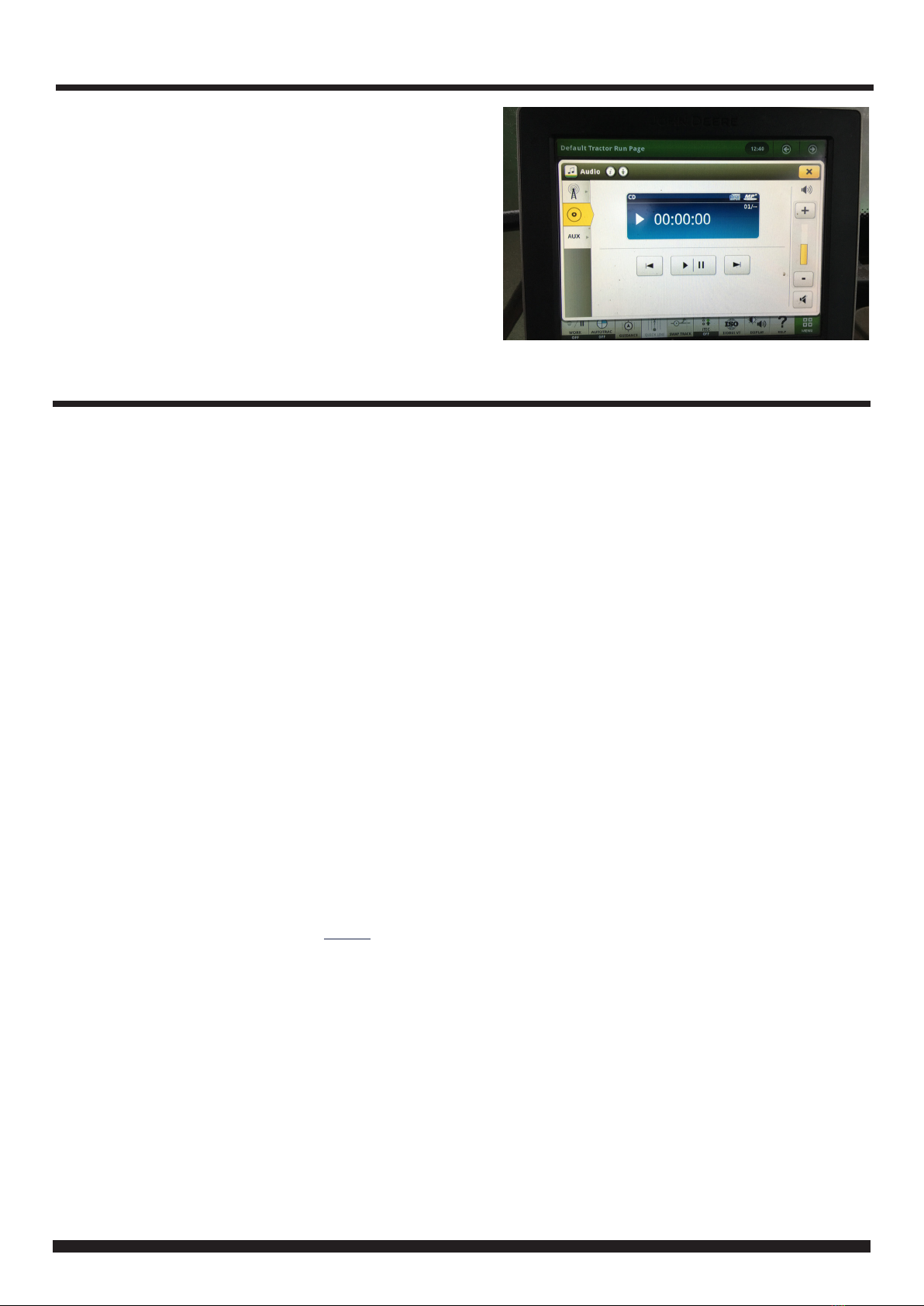
OEM DISPLAY FUNCTIONALITY
Once the aftermarket radio is installed, the OEM display
will show the CD home page screen.
Volume +, Volume -, Track +, Track - and Mute functions
will work as when the OEM head unit was installed. The
play/pause buttons will now perform the source func-
tion on the aftermarket radio.
Note: The yellow display bar will not move when volume is
adjusted.
Pressing the tabs (Radio, AUX) on the left hand side of
the screen will cause the screen to change for around 2
seconds before reverting back to the CD screen.
4CTSJD001.2_IG_en-GB_v1
WIRING DIAGRAM
ISO Connector [16 Pin]
Connect to aftermarket stereo
Mini ISO Connector [26 Pin]
Connect to corresponding connector from vehicle
Stereo Connection (Patch) Lead Connector [12 Pin]
Connect to Interface Box
Note: Must be connected first, before power connection is
made to the interface
Main Wiring Loom Connector [14 Pin]
Connect to Interface Box
Interface Box
Female USB Connector
Connect to vehicle
DAB
Splitter
DIN Male & SMB Connector
Connect to aftermarket stereo
DIN Female
Connect to original
antenna Male DIN
Flying Wire [Blue]
Connect to vehicle
antenna power
3.5mm Jack Connector
Connect to AUX input on aftermarket
stereo
Male USB Connector
Connect to aftermarket stereo