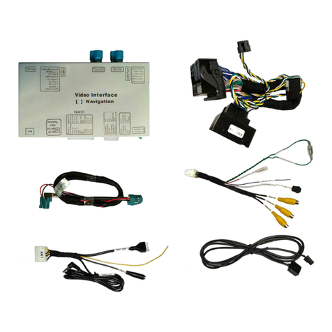
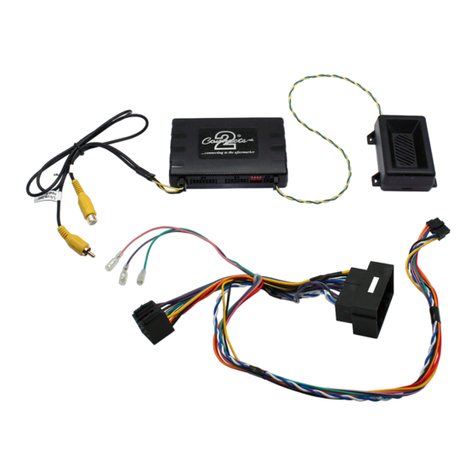
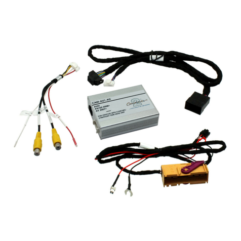
Connects2 CT23DG06 User manual
Other Connects2 Automobile Accessories manuals
Connects2
Connects2 CT23TY82 User manual

Connects2
Connects2 CTKIV02 User manual

Connects2
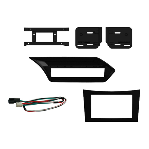
Connects2 CTULR04 User manual
Connects2
Connects2 CT23MB26L User manual

Connects2
Connects2 CT23AU12/L User manual

Connects2
Connects2 CAM-MB5 User manual

Connects2
Connects2 CT53-PO05 User manual

Connects2
Connects2 CT23MB25/L User manual

Connects2
Connects2 CAM-54 User manual

Connects2
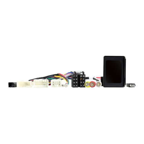
Connects2 CTUAR01 User manual
Connects2
Connects2 CTSMT011.2 User manual

Connects2
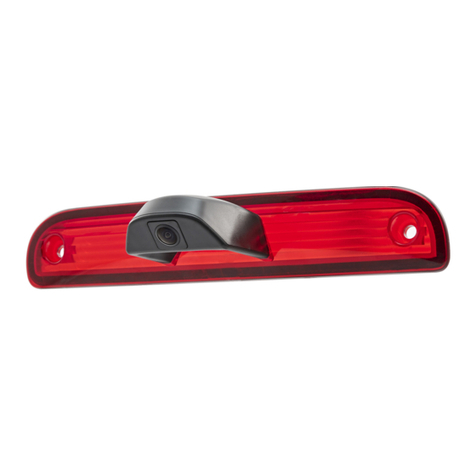
Connects2 CAM-32 User manual
Connects2
Connects2 Gator G162V User manual

Connects2
Connects2 AdaptivMini ADVM-AU6 User manual

Connects2
Connects2 CAM-MB2-AD User manual

Connects2
Connects2 CAN-Connect CANHBJP1 User manual
Connects2
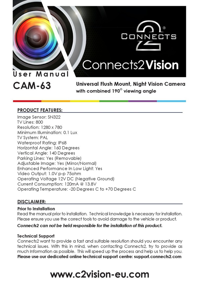
Connects2 CAM-63 User manual

Connects2
Connects2 CAM-MB14 User manual
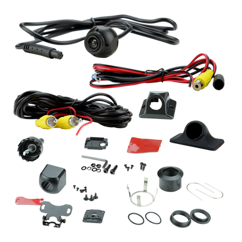
Connects2
Connects2 CAM-35 User manual

Connects2
Connects2 43uft03 User manual
Popular Automobile Accessories manuals by other brands

ULTIMATE SPEED
ULTIMATE SPEED 279746 Assembly and Safety Advice

SSV Works
SSV Works DF-F65 manual

ULTIMATE SPEED
ULTIMATE SPEED CARBON Assembly and Safety Advice

Witter
Witter F174 Fitting instructions

WeatherTech
WeatherTech No-Drill installation instructions

TAUBENREUTHER
TAUBENREUTHER 1-336050 Installation instruction
