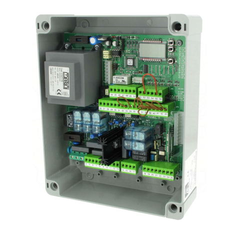
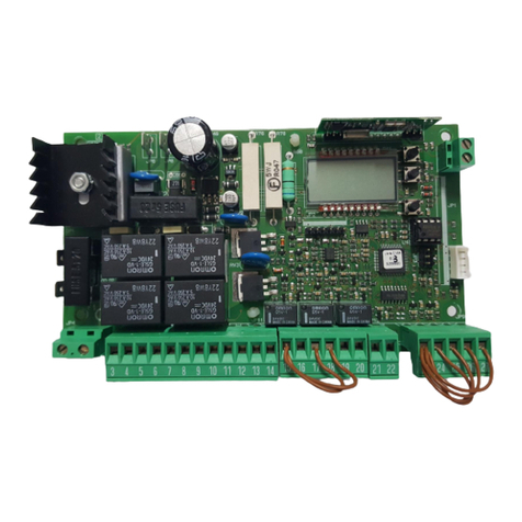
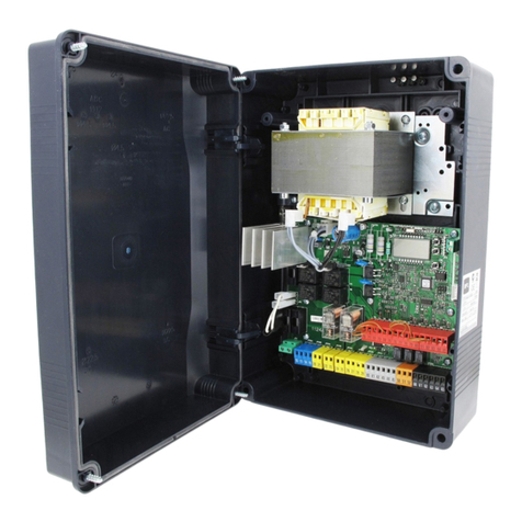
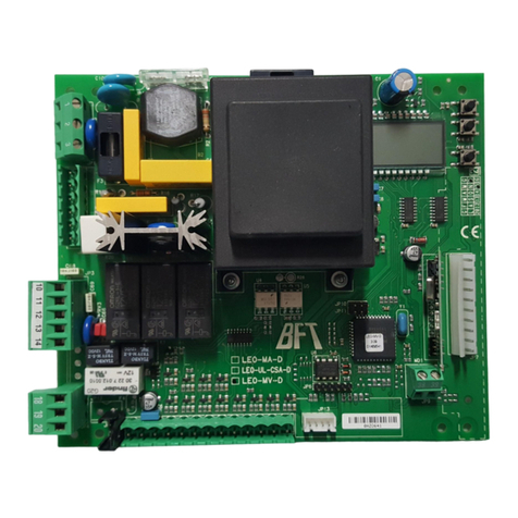
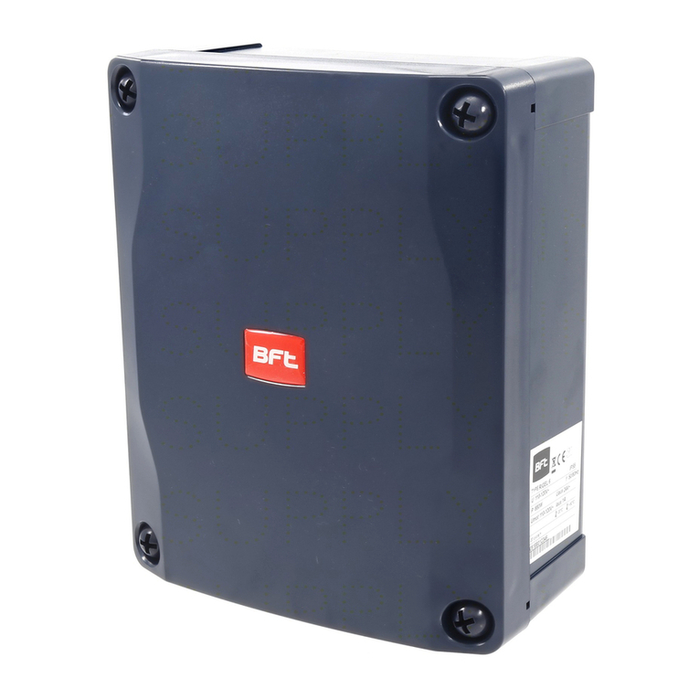
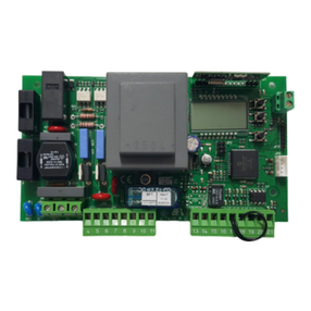
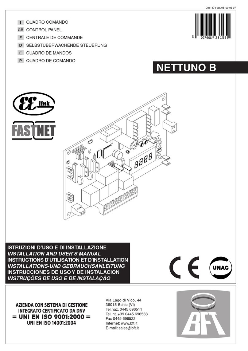
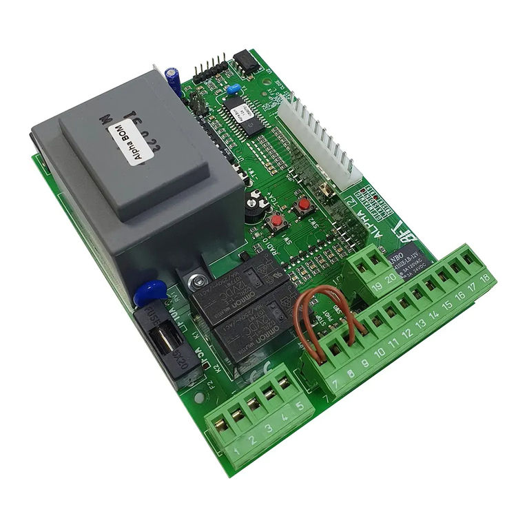
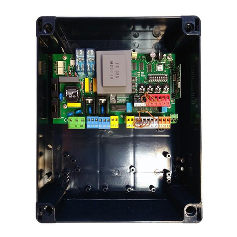
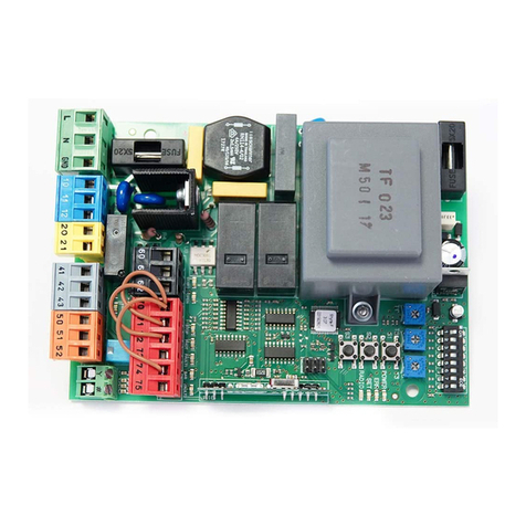
BFT LEO B CBB DL2 3 230 L02 User manual


606162707172737475
COMSAFE 1FAULT 1STOPSAFE 2FAULT 2
NCNCNC
COMFAULT 3SAFE 3
NC
767778
636465
COMIC 1IC 2
NONO
COMIC 3IC 4
NONO
LNLN2021
+ REF SWESWC **
SWO **
2627505152
24V ~24V ~24 VSafe
AB10LN111220212660JP3261626364657071727374757677782740414243505152Y#
F2= 6,3 AF
LEO B CBB DL2 3 230 L02
F2= 6,3 AT
LEO B CBB DL2 3 230 SV
F2= 10 AF
LEO B CBB DL2 3 120 F02/LEO B CBB DL2 3 120 F02 USA16
Y#
ANTSHIELD
GND
GND
26
AUX 3 = 1
27
12
26275051
24 V~SCA
** *
LEO B CBB DL2 3 120 F02 USA16
VOLUME CONTROLABCDESOUND PATTERN SELECTIONSOUND PATTERNSELECTION1 CONTINUOUS link A2 LONG PIP link A & E3 SHORT PIP link A & D4 SHRIEK 1 link A B D5 SHRIEK 2 link A C E6 WARBLE 1 link A & B7 WARBLE 2 link A & C8 TWO TONE 1 link B9 TWO TONE 2 link C
ALARM
ALARM24 Vd.c.
F1= 315mAT
LEO B CBB DL2 3 230 L02 / LEO B CBB DL2 3 230 SV
F1= 630mAT
LEO B CBB DL2 3 120 F02 / LEO B CBB DL2 3 120 F02 USA16
4041424360JP3261
62
2x0.5mm
2
3x1.5mm
2
RG58
3x1.5mm
2
3x1.5mm
2
5x0,5mm
2
2x1.5mm
2
AUX 3 = 1
220230V
AUX 0 - 220-230V~ (L02)
120V~ (F02)(40W MAX)
LEO B CBB DL2 3 230 L02LEO B CBB DL2 3 120 F02LEO B CBB DL2 3 230 SV
AUX 3 MAX 24V 0,5A
10111213MBN
Mc
Connettore programmatore palmare, Palmtop programmer connector, Connecteur programmateur de poche, Steckverbinder Palmtop-Programmierer, Conector del programador de bolsillo, Connector programmeerbare palmtop.Connettore per ricevente radioRadio-receiver connector Connecteur pour récepteur radioSteckverbindung für Funkempfänger Conector para receptor radio Connector voor radio-ontvanger Connettore encoderEncoder connectorConnecteur encodeurSteckverbindung EncoderConector encoderStekker encodersolo per / only for / uniquement surnur für / solo para / apenas paraLEO B CBB DL2 3 230 SVComandi / CommandsCommandes /BedienelementeMandos/ Commando’sAlimentazione / Power supplyAlimentation / StromversorgungAlimentación / Voeding**Con logica inversione direzione di apertura = 000 (DIR=DX) / **With reverse logic, opening direction = 000 (DIR=right) / ** Avec logique inversion direction d’ouverture = 000 (DIR=DRT) **Mit Inversionslogik Önungsrichtung = 000 (DIR=rechts) / **Con lógica inversión dirección de apertura = 000 (DIR=DER) / **Met logica omkering openingsrichting = 000 (DIR=R)Motore / Motormoteur / MotorEindaanslag / Motor Ingressi necorsaLimit switch inputsEntrées des ns de courseEingänge AnschlagEntradas nales de carreraIngangenAlimentazione accessoriAccessories power supplyAlimentation des accessoiresStromversorgung ZubehörAlimentación accesoriosVoeding accessoiresAntennaAntenneAntenaAntenneAUXSicurezze / Safety devicesSécurités / SicherheitsvorrichtungenDispositivos de seguridad / VeilighedenConnettore scheda opzionaleOptional board connectorConnecteur carte facultativeSteckverbinder ZusatzkarteConector de la tarjeta opcional Connector optionele kaartCollegamento necorsa magneticoMagnetic limit switch connectionConnexion du n de course magnétiqueAnschluss Magnet-EndschalterConexión nal de carrera magnéticoVerbinding magnetische begrenzerNon collegare o ponticellare se è presente il necorsa magneticoDo not connect or jump if there is the magnetic limit switchNe pas connecter, ni poser de pontet en présence du n de course magnétiqueNicht anschließen oder überbrücken, falls der Magnet-Endschalter vorhanden istNo conecte ni puentee si el nal de carrera magnético está presenteNiet verbinden of een brug aanbrengen als de magnetische begrenzer er is
INSTALLAZIONE VELOCE-QUICK INSTALLATION-INSTALLATION RAPIDESCHNELLINSTALLATION-INSTALACIÓN RÁPIDA - SNELLE INSTALLATIEMBNMARRONEBLUNEROBROWN BLUE BLACKMARRON BLEU NOIRBRAUN BLAU SCHWARZMARRÓN AZULNEGROBRUIN BLAUW ZWART
Display + tasti programmazioneDisplay + programming keysAcheur + touches programmationDisplay + ProgrammierungstastenPantalla + botones programaciónDisplay + programmeringstoetsen
2 - LEO B CBB DL2 3 230 L02-LEO B CBB DL2 3 120 F02-LEO B CBB DL2 3 120 F02 PHOT USA16 - LEO B CBB DL2 3 230 SV
D814094 0AA00_01

ENGLISHFRANÇAISESPAÑOL
NEDERLANDS
DEUTSCHITALIANO
C2C172515070
24V ~
21
TX121RX1453
SAFE 1 = 0SAFE 1 = 1
72515070
24V ~Vsafe
7352
21
TX121RX1453Fotocellule non vericate (Check ogni 6 mesi)Photocells not checked (Check every 6 months)Photocellules non vériées (contrôle tous les 6 mois)Fotozellen nicht überprüft (alle 6 Monate überprüfen)Fotocélulas no controladas (Control cada 6 meses)Fotocellen niet gecontroleerd (Check elke 6 maanden)Fotocellula vericataPhotocell checkedPhotocellule vériéeFotozelle überprüftFotocélula controladaFotocel gecontroleerd LEO B CBB DL2 3 230 L02-LEO B CBB DL2 3 120 F02-LEO B CBB DL2 3 120 F02 PHOT USA16 - LEO B CBB DL2 3 230 SV 3
D814094 0AA00_01

ENGLISHFRANÇAISESPAÑOL
NEDERLANDS
DEUTSCHITALIANO
: automatic operation, residential: semiautomatic operation, residential: automatic operation, commercial: semiautomatic operation, commercial: dead man operationExit Menù
Conrm/Switchon display
Scroll upScroll down***** Password entry. Request with Protection Level logic set to 1, 2, 3, 4langDirITAfradeuengespSxarsracScIndDxARpresete
O 01
re otessracscind
end
autoset. . . . . .
o o
OPENOPEN0enco12AUTO OPENAUTO CLOSE
MIN 1 - MAX 3
x1
0---10--150-1520ok
***** lhrh
hidden button
release
desidered button
SIMPLIFIED MENU
PRESETDEFAULTarsracscindPARAMETERS
Opening operation time [s]
300Set by autosetClosing operation time [s]300Set by autoset
Slow-down distance during opening [%]
30Set by autosetSlow-down distance during closing [%]30Set by autosetLeaf force during opening [%]75Set by autosetLeaf force during closing [%]
75
Set by autoset
Leaf/leaves force during opening during slow-down
[%]75Set by autoset
Leaf/leaves force during closing during slow-down [%]
75Set by autoset
Braking[%]
0Set by autosetLOGICAutomatic Closing Time010100Step-by-step movement010100Encoder2/////Pre-alarm000110Deadman000001Block pulses during opening 000110
Open in other direction
0/////SAFE 1044440
SAFE 2
6/////SAFE 32/////IC 10/////IC 24/////IC 32/////IC 43/////AUX 3** 0/////EXPI11/////EXPI20/////EXPO111/////EXPO211/////
**Not active on LEO B CBB DL2 3 120 F02 PHOT USA16
Only for sw versions 6.08/7.08/8.08
EncoderDisabledEncoder enabled only as a position sensor
Encoder enabled for position and for obstacle detection
refer to Table B“encoder” LEO B CBB DL2 3 230 L02-LEO B CBB DL2 3 120 F02-LEO B CBB DL2 3 120 F02 PHOT USA16 - LEO B CBB DL2 3 230 SV 5
D814094 0AA00_01

D767778
SAFE 3FAULT 3
NC
COM
NC
121234551TX1RX1Bar 112345612123455250TX1RX11212345TX1RX11212345TX2RX2Bar 112345Bar 212345Bar 1123456661212345TX1RX1Bar 11234561212345TX1RX11212345TX1RX11212345TX2RX2Bar 112345Bar 212345Bar 112345666
SAFE1 = 0,2,4
SAFE1 = 8,11,14
1 PHOT / 1 PHOT OP / 1 PHOT CL1 PHOT / 1 PHOT OP / 1 PHOT CL2 PHOT / 2 PHOT OP / 2 PHOT CLBAR 8K2 / BAR 8K2 OP / BAR 8K2 CL1 BAR / 1 BAR OP / 1 BAR CL1 BAR / 1 BAR OP / 1 BAR CL2 BAR / 2 BAR OP / 2 BAR CL5052505250515051505150515070727072737070727351515051505150525252727072707372705150707370728,2Kohm 5%SAFETY EDGESAFETY EDGE70748,2Kohm 5%SAFETY EDGESAFETY EDGE121234551TX1RX1Bar 112345612123455250TX1RX11212345TX1RX11212345TX2RX2Bar 112345Bar 212345Bar 1123456661212345TX1RX1Bar 11234561212345TX1RX11212345TX1RX11212345TX2RX2Bar 112345Bar 212345Bar 112345666
SAFE2 = 0,2,4
SAFE2 = 6,9,12
SAFE1 = 1,3,5
SAFE2 = 1,3,5SAFE2 = 7,10,13
1 PHOT / 1 PHOT OP / 1 PHOT CL1 PHOT / 1 PHOT OP / 1 PHOT CL2 PHOT / 2 PHOT OP / 2 PHOT CL1 BAR / 1 BAR OP / 1 BAR CL1 BAR / 1 BAR OP / 1 BAR CL2 BAR / 2 BAR OP / 2 BAR CL5052505250515051505150515070747074757070747551515051505150525252747074707574705150707572507071737475
24V -24V +24 VSafe+COMSAFE 1SAFE 2STOPFAULT 1FAULT 2
NCNCNC
7071737475
24V -24V +24 VSafe+COMSAFE 1SAFE 2STOPFAULT 1FAULT 2
NCNCNC
121234551TX1RX1Bar 112345612123455250TX1RX11212345TX1RX11212345TX2RX2Bar 112345Bar 212345Bar 1123456661212345TX1RX1Bar 11234561212345TX1RX11212345TX1RX11212345TX2RX2Bar 112345Bar 212345Bar 112345666
SAFE3 = 0,2,4
SAFE3 = 6,9,12
1 PHOT / 1 PHOT OP / 1 PHOT CL1 PHOT / 1 PHOT OP / 1 PHOT CL2 PHOT / 2 PHOT OP / 2 PHOT CL50525052505150515051505150767776777876767778515150515051505252527776777678777651507678
SAFE3 = 1,3,5
SAFE3 = 7,10,13
5152SAFE2SAFE 3125132451324
TEST OFFTEST ONTEST OFFTEST ONTEST OFFTEST ON
SAFE 1SAFE 2
SAFE1 = 6,9,12
SAFE1 = 7,10,13
34
SAFE1 = 8,11,14
2 BAR / 2 BAR OP / 2 BAR CL1 BAR / 1 BAR OP / 1 BAR CL1 BAR / 1 BAR OP / 1 BAR CLBAR 8K2 / BAR 8K2 OP / BAR 8K2 CL10 - LEO B CBB DL2 3 230 L02-LEO B CBB DL2 3 120 F02-LEO B CBB DL2 3 120 F02 PHOT USA16 - LEO B CBB DL2 3 230 SV
D814094 0AA00_01

ENGLISHFRANÇAISESPAÑOL
NEDERLANDS
DEUTSCHITALIANO
E10LN11122021266061626364657071727374757677782740414243505152Y#
GND
10LN11122021266061626364657071727374757677782740414243505152Y#
GND
E
SCHEDA DI ESPANSIONE
EXPANSION BOARDCARTE D’EXPANSIONERWEITERUNGSKARTETARJETA DE EXPANSIÓNUITBREIDINGSKAARTProgrammeerbare Universele Palmtop
UNIDA
FTX1 (PHOT)RX1 (PHOT)CC1(BAR)CC2(BAR)TX2 (PHOT)RX2 (PHOT)M2SLAVEM1MASTERiNDIRIZZO=0address=0adresse=0adresse=0direccion=0modo seriale=3serial mode=3mode serie=3serieller modus=3modo seria=3iNDIRIZZO=0address=0adresse=0adresse=0direccion=0modo seriale=2serial mode=2mode serie=2serieller modus=2modo seria=2ESEMPIO APPLICAZIONE ANTE CONTRAPPOSTE CON 2 PHOT E 2 BAR - SAMPLE APPLICATION WITH OPPOSITE LEAVES WITH 2 PHOT AND 2 BAR - EXEMPLE D’APPLICATION VANTAUX OPPOSÉS AVEC 2 PHOT ET 2 BAR - ANWENDUNGSBEISPIEL EINANDER ENTGEGENGESETZTE TORFLÜGEL MIT 2 PHOT UND 2 BAR - VOORBEELD TOEPASSING TEGENOVERGESTELDE VLEUGELS MET 2 PHOT EN 2 BAR505152CC2707172737475767778SAFE 1 = 1SAFE 2 = 7 (≥6)SAFE 3 = 15051526160TX1RX1TX2CC1RX262636465707172737475767778STARTSTOPMAX 250m
B EBA RS485 LINKB EBA RS485 LINK
MASTERSLAVE(versione x.40 e successive)(x.40 and later versions)(version x.40 et suivantes)(Version x.40 und nachfolgende)(versión x.40 y sucesivas )(versie x.40 en hoger)
MASTER e SLAVE devono avere la stessaversione di rmware e la stessa impostazione di SAFE2.
MASTER and SLAVE must have the same rmware version and the same setting for SAFE2.MASTER et SLAVE doivent avoir la même version rmware et la même conguration de SAFE2.
MASTER und SLAVE müssen dieselbe Firmware-Ver-sion und dieselbe Einstellung von SAFE2 haben.
MASTER y SLAVE deben tener la misma versión de rmware y la misma conguración de SAFE2.MASTER en SLAVE moeten dezelfde rmwareversie en dezelfde instelling van SAFE2 hebben.
LEO B CBB DL2 3 230 L02-LEO B CBB DL2 3 120 F02-LEO B CBB DL2 3 120 F02 PHOT USA16 - LEO B CBB DL2 3 230 SV 11
D814094 0AA00_01

GDIR= dK
DIR= sK12
HS1
S2
S3
+
-
OK
S1
S2
S3
+
-
OK
7071
COM
STOP
S1
S2
S3
+
-
OK
S1
S2
S3
+
-
OK
8888rst88888....123465
!
<3s+
OFF
ON
verso di apertura: destraopening direction: rightsens de l’ouverture : droiteÖnungsrichtung: rechtssentido de apertura: derechaopeningsrichting: rechtsversoInversione direzione di apertura: 001Open in other direction: 001Inversion direction de l’ouverture: 001Richtungsumkehrung Önung: 001Inversión dirección de apertura: 001Openingsrichting omdraaien: 001- Nel passaggio di congurazione logica da apertura destra/sinistra, non invertire il collegamento originale dei morsetti 42-43.- When switching logic conguration from right to left opening, do not swap over original connection of terminals 42-43.- Lors du passage de conguration logique de l’ouverture droite/gauche, n’inversez pas la connexion d’origine des bornes 42-43- Bei der Änderung der Logik Önung rechts/links nicht den Originalanschluss der Klemmen 42-43 verändern.- En el paso de conguración lógica de apertura derecha/izquierda no invertir la conexión original de los bornes 42-43.- Bij de overgang van de logica conguratie van rechts/links openen, de oorspronkelijke aansluiting van de klemmen 42-43 niet omdraaien.Inversione direzione di apertura: 000Open in other direction: 000Inversion direction de l’ouverture: 000Richtungsumkehrung Önung: 000Inversión dirección de apertura: 000Openingsrichting omdraaien: 000verso di apertura: sinistraopening direction: leftsens de l’ouverture : gaucheÖnungsrichtung: linkssentido de apertura: izquierdaopeningsrichting: links12 - LEO B CBB DL2 3 230 L02-LEO B CBB DL2 3 120 F02-LEO B CBB DL2 3 120 F02 PHOT USA16 - LEO B CBB DL2 3 230 SV
D814094 0AA00_01

INSTALLATION MANUALACCESS MENUS Fig. 1
autosetExit MenùConrm/Switch on displayScroll upScroll downSee PARAMETERS MENUSee LOGIC MENU
language
stat
-+-+
OK
vers
bft . . .
+/-
OK
0000
+/- +/-
n. cycles
OKOK
01.33
password
0---10--150-1520prg
00
-+
err
02.01........30.15
+/-
n. remotes
List of last 30 errorsControl unitsoftware versionNo total
manoeuvres(in hundreds)
No radio controldevices memorised
ALTfollow the user guide
x2
0---10--150-1520ok
*** Password entry.Request with Protection Level logic set to 1, 2, 3, 4*** See RADIO MENU
hidden butt
releasedesired button
Add. 2ch
hidden butt
releasedesired button
hidden butt
releasedesired button
Add. 4ch
hidden butt
releasedesired button
Add. 1chAdd. 3ch
If cancelledIf not presentIf clone, it is disabled(
0001
)okKOdis
erase 1erase 64
only with Encoder= 235.40
Obstacle threshold
Instantaneous force motor
Diagnostics codeDESCRIPTIONNOTESSTRESTART E external start input activatedSTRISTART I internal start input activatedOPENOPEN input activatedCLSCLOSE input activatedPEDPED pedestrian input activatedTIMETIMER input activatedSTOPSTOP input activatedPHOTActivation of PHOT photocell input or, if congured as veried photocell, Activation of the associated FAULT inputPHOPActivation of PHOT OP opening photocell input or, if congured as active veried photocell only when opening, Activation of the associated FAULT inputPHCLActivation of PHOT CL closing photocell input or, if congured as active veried photocell only when closing, Activation of the associated FAULT inputBARActivation of BAR safety edge input or, if congured as veried safety edge, Activation of the associated FAULT inputBAR 2Activation of BAR safety edge input on slave motor (opposing door connection) or, if congured as veried safety edge, Activation of the associated FAULT inputbaroActivation of BAR safety edge input with ACTIVE reversal ONLY WHILE OPENING, or, if congured as veried safety edge active only while opening, Activation of the associated FAULT inputbarcActivation of BAR safety edge input with ACTIVE reversal ONLY WHILE CLOSING, or, if congured as veried safety edge active only while closing, Activation of the associated FAULT input SWCSWC motor closing limit switch input activatedSWO SWO motor opening limit switch input activatedSETThe board is standing by to perform a complete opening-closing cycle uninterrupted by intermediate stops in order to acquire the torque required for movement. WARNING! Obstacle detection not activeRLSActivation of mechanical release of the motor. The following manoeuvre will be performed at low speed.ER01Photocell test failedCheck photocell connection and/or logic settingsER02Safety edge test failedCheck safety edge connection and/or logic settingsER03Opening photocell test failedCheck photocell connection and/or parameter/logic settingER04Closing photocell test failedCheck photocell connection and/or parameter/logic settingER05Safety edge test on slave motor failed (opposite leaves connection)Check safety edge connection and/or parameter/logic settingser068k2 safety edge test failedCheck safety edge connection and/or parameter/logic settingsER07Opening safety edge test failedCheck safety edge connection and/or parameter/logic settingsER08Closing safety edge test failedCheck safety edge connection and/or parameter/logic settingsEr10, Er11Board hardware test error-Check connections to motor -Hardware problems with board (contact technical assistance)Er35, Er36Er37, Er38Reverse due to obstacle - AmperostopCheck for obstacles in path Ensure that there is no slip in the mechanical clutchER50Communication error with remote devicesCheck connection with serial-connected accessory devices and/or expansion boards ER70, ER71ER74, ER75Internal system supervision control error.Try switching the board o and back on again. If the problem persists, contact the technical assistance department.ER72Consistency error of the control unit’s parameters (Logics and Parameters)Pressing OK the detected settings are conrmed. The board will keep on working with the detected settings. The board settings must be checked (Parameters and Logics) ER73D-track parameter errorPressing OK, the board will keep on working with D-track as a default.An autoset is requiredERf0Limit switch errorcheck limit switch connectionserf1Limit switch error always active after operation startCheck limit switch and motor connectionsERf3Error in setting the SAFE inputsCheck the setting of the SAFE inputs is correct22 - LEO B CBB DL2 3 230 L02-LEO B CBB DL2 3 120 F02-LEO B CBB DL2 3 120 F02 PHOT USA16 - LEO B CBB DL2 3 230 SV
D814094 0AA00_01

INSTALLATION MANUAL
2) GENERAL INFORMATIONTheLEO B CBB DL2 3 230 L02 - LEO B CBB DL2 3 230 SV - LEO B CBB DL2 3 120 F02- LEO B CBB DL2 3 120 F02 PHOT USA16 control panel comes with standard factory settings. Any change must be made using the programmer with built-in display or universal handheld programmer.
The Control unit completely supports the EELINK protocol.
Its main features are: - Control of 1 single-phase motor - Electronic torque control
- Detection of obstacles through safety bar- Detection of obstacles through encoder (only for LEO B CBB DL2 3 230 L02 - LEO B CBB DL2 3 120 F02- LEO B CBB DL2 3 120 F02 PHOT USA16)
- Separate inputs for safety devices- Congurable command inputs- Built-in radio receiver rolling code with transmitter cloning.The board has a terminal strip of the removable kind to make maintenance or replacement easier. It comes with a series of prewired jumpers to make the installer’s job on site easier.The jumpers concern terminals: 70-71, 70-72, 70-74, 76-77. If the above-mentioned terminals are being used, remove the relevant jumpers. protect the dangerous rims according to the provisions of the EN12453 regulation, applying active edges and using the SAFE1 and SAFE2 inputs (for the active edge models refer to the model table at paragraph 2)LEO B CBB DL2 3 230 L02LEO B CBB DL2 3 120 F02
LEO B CBB DL2 3 120 F02 PHOT USA16
LEO B CBB DL2 3 230 SVPower supply
220-230V~ 50Hz/60Hz120V~ ±10% 50Hz/60Hz120V~ ±10% 50Hz/60Hz220-230V~ 50Hz/60HzObstacle detection with encoderPresentPresent
Only for sw versions
7.08
Present
Only for sw versions 8.08
MISSING For obstacle detection, apply a safety edge: ASO SENTIR EDGE 115SK / BIRCHER EP45x99A1 (NOT SUPPLIED)
Output for terminals 26-27: N.O. contact (24V~/0,5A)
AUX3 congurableAUX3 congurableOutput for audible signalAUX3 congurable
TESTINGThe LEO B CBB DL2 3 230 L02 - LEO B CBB DL2 3 230 SV - LEO B CBB DL2 3 120 F02- LEO B CBB DL2 3 120 F02 PHOT USA16 panel controls (checks) the start relays and safety devices (photocells) before performing each opening and closing cycle. If there is a malfunction, make sure that the connected devices are working properly and check the wiring.3) TECHNICAL SPECIFICATIONSPower supply
220-230V~ 50Hz/60Hz
(LEO B CBB DL2 3 230 L02)(LEO B CBB DL2 3 230 SV)
120V~ ±10% 50Hz/60Hz
(LEO B CBB DL2 3 120 F02/ LEO B CBB DL2 3 120 F02 PHOT USA16)
Low voltage/mains insulation> 2MOhm 500V Operating temperature range-20 / +55°CThermal overload protectionBuilt into motorDielectric rigiditymains/LV 3750V~ for 1 minuteMaximum motor power750WAccessories power supply24V~ (demand max. 1A)24V~safeAUX 0220-230V~N.O. (40W max)
(LEO B CBB DL2 3 230 L02)
powered contact
120V~N.O. (40W max)
(LEO B CBB DL2 3 120 F02/ LEO B CBB DL2 3 120 F02 PHOT USA16)
powered contact
AUX 3/ Output for audible signalNO contact (24V~/max.0,5A) Dimensions146x170x60mmFusessee Fig. BN° of combinations4 billion
Max.n° of transmitters that can be memorized
63Usable transmitter versions:All ROLLING CODE transmitters compatible with 4) TUBE ARRANGEMENT Fi g. A5) TERMINAL BOARD WIRING Fig. BWARNINGS - When performing wiring and installation, refer to the standards in force and, whatever the case, apply good practice principles.Wires carrying dierent voltages must be kept physically separate from each other, or they must be suitably insulated with at least 1mm of additional insulation. Wires must be secured with additional fastening near the terminals, using devices such as cable clamps.All connecting cables must be kept far enough away from the dissipater.WIRING AND TERMINAL BOARD CONFIGURATIONTerminalDenitionDescription
Powersupply
LLINESingle-phase power supply 220-230V~ 50/60Hz, with earth cable(LEO B CBB DL2 3 230 L02 - LEO B CBB DL2 3 230 SV).Single-phase power supply 120V~ ±10%, 50-60Hz, with earth cable(LEO B CBB DL2 3 120 F02/ LEO B CBB DL2 3 120 F02 PHOT USA16).NNEUTRALGNDEARTH
Motor
10 START + CAPMotor connection.START + CAP Motor Start and capacitorCOM Motor CommonSTART + CAP Motor Start and capacitor11COM12START + CAP13COND BOOST10-13 Additional “boost” condenser connection (only for LEO B CBB DL2 3 230 SV)
Aux
20
AUX 0 -
POWERED CONTACT
220 230V~
(LEO B CBB DL2 3 230 L02)(LEO B CBB DL2 3 230 SV)POWERED CONTACT
120V~
(LEO B CBB DL2 3 120 F02)
(LEO B CBB DL2 3 120 F02 PHOT USA16)
AUX 0 congurable output - Default setting FLASHING LIGHT. MONOSTABLE RADIO CHANNEL/ SCA GATE OPEN LIGHT/ COURTESY LIGHT command/ ZONE LIGHT command/ STAIR LIGHT/ GATE OPEN ALARM/ FLASHING LIGHT/ SOLENOID LATCH/ MAGNETIC LOCK/ MAINTENANCE/ FLASHING LIGHT AND MAINTE-NANCE / ANTITAMPERING / GATE STATUS / BISTABLE RADIO CHANNEL / TIMED RADIO CHANNEL. Refer to “AUX output conguration” table.2126AUX 3 - FREE CONTACT (N.O.) LEO B CBB DL2 3 230 L02 (LEO B CBB DL2 3 230 SV) LEO B CBB DL2 3 120 F02AUX 3 congurable output - Default setting MONOSTABLE RADIO CHANNEL Output. MONOSTABLE RADIO CHANNEL/ SCA GATE OPEN LIGHT/ COURTESY LIGHT command/ ZONE LIGHT command/ STAIR LIGHT/ GATE OPEN ALARM/ FLASHING LIGHT/ SOLENOID LATCH/ MAGNETIC LOCK/ MAINTENANCE/ FLASHING LIGHT AND MAINTENANCE / GATE STATUS / BISTABLE RADIO CHANNEL / TIMED RADIO CHANNEL. Refer to “AUX output conguration” table.2726
OUTPUT CONFIGURED AS UL ALARM
LEO B CBB DL2 3 120 F02 PHOT USA16
Activation: 2 consecutive obstacle detections uninterrupted by an end stopDeactivation: after 300s or after removal of the “STOP” input27
Motor limit switch 1 (model not ULTRA)
41+ REF SWELimit switch common42SWCClosing limit switch SWC (N.C.). (Do not connect or jump if there is the magnetic limit switch)43SWO- Opening limit switch SWO (N.C.). (NDo not connect or jump if there is the magnetic limit switch)
Motor magnetic
limit switch 1
JP32Magnetic limit switch connection
Accessoriespowersupply
5024V-Accessories power supply output.5124V+5224 Vsafe+Tested safety device power supply output (photocell transmitter and safety edge transmitter). Output active only during operating cycle. LEO B CBB DL2 3 230 L02-LEO B CBB DL2 3 120 F02-LEO B CBB DL2 3 120 F02 PHOT USA16 - LEO B CBB DL2 3 230 SV 23
D814094 0AA00_01
ENGLISH
INSTALLATION MANUAL
TerminalDenitionDescription
Commands
60CommonIC 1 and IC 2 inputs common61IC 1Congurable command input 1 (N.O.) - Default START E. START E / START I / OPEN / CLOSE / PED / TIMER / TIMER PED Refer to the “Command input conguration” table.62IC 2Congurable command input 2 (N.O.) - Default PED. START E / START I / OPEN / CLOSE / PED / TIMER / TIMER PED Refer to the “Command input conguration” table.63CommonIC 3 and IC 4 inputs common64IC 3Congurable command input 3 (N.O.) - Default OPEN. START E / START I / OPEN / CLOSE / PED / TIMER / TIMER PED Refer to the “Command input conguration” table.65IC 4Congurable command input 4 (N.O.) - Default CLOSE. START E / START I / OPEN / CLOSE / PED / TIMER / TIMER PED Refer to the “Command input conguration” table.
Safety devices
70CommonSTOP, SAFE 1 and SAFE 2 inputs common71STOP The command stops movement. (N.C.) If not used, leave jumper inserted.72SAFE 1Congurable safety input 1 (N.C.) - Default PHOT.
PHOT / PHOT TEST / PHOT OP / PHOT OP TEST / PHOT CL / PHOT CL TEST / BAR / BAR TEST / BAR 8K2 /
BAR OP / BAR OP TEST / BAR 8K2 OP/ BAR CL / BAR CL TEST / BAR 8K2 CL Refer to the “Safety input conguration” table.73FAULT 1 Test input for safety devices connected to SAFE 1.74SAFE 2Congurable safety input 2 (N.C.) - Default BAR.
PHOT / PHOT TEST / PHOT OP / PHOT OP TEST / PHOT CL / PHOT CL TEST / BAR / BAR TEST / BAR 8K2 /
BAR OP / BAR OP TEST / BAR 8K2 OP/ BAR CL / BAR CL TEST / BAR 8K2 CL Refer to the “Safety input conguration” table.75FAULT 2 Test input for safety devices connected to SAFE 2.76CommonSAFE 3 input common77SAFE 3Congurable safety input 3 (N.C.) - Default PHOT OP.
PHOT / PHOT TEST / PHOT OP / PHOT OP TEST / PHOT CL / PHOT CL TEST / BAR / BAR TEST / BAR OP / BAR OP TEST / BAR CL / BAR CL TEST.
Refer to the “Safety input conguration” table.78FAULT 3Test input for safety devices connected to SAFE 3.
Anten-na
YANTENNAAntenna input. Use an antenna tuned to 433MHz. Use RG58 coax cable to connect the Antenna and Receiver. Metal bodies close to the an-tenna can interfere with radio reception. If the transmitter’s range is limited, move the antenna to a more suitable position.#SHIELDAUX output congurationAux logic= 0 - MONOSTABLE RADIO CHANNEL output. Contact stays closed for 1s when radio channel is activated. Aux logic= 1 - SCA GATE OPEN LIGHToutput. Contact stays closed during opening and with leaf open, intermittent during closing, open with leaf closed.Aux logic= 2 - COURTESY LIGHT command output. Contact stays on for 90 seconds after the last operation.Aux logic= 3 - ZONE LIGHT command output. Contact stays closed for the full duration of operation.Aux logic= 4 - STAIR LIGHT output. Contact stays closed for 1 second at start of operation. Aux logic= 5 - GATE OPEN ALARM output. Contact stays closed if the leaf stays open for double the set TCA time.Aux logic= 6 - FLASHING LIGHT output. Contact stays closed while leaves are operating.Aux logic= 7 - SOLENOID LATCH output. Contact stays closed for 2 seconds each time gate is opened or closed.Aux logic= 8 - MAGNETIC LOCK output. Contact stays closed when gate is closed and while it is closing.Aux logic= 9 - MAINTENANCE output.Contact stays closed once the value set for the Maintenance parameter is reached, to report that maintenance is required. Aux logic= 10 - FLASHING LIGHT AND MAINTENANCE output.Contact stays closed while leaves are operating. If the value set for the Maintenance parameter is reached, once the gate has nished moving and the leaf is closed, the contact closes for 10 sec. and opens for 5 sec. 4 times to report that maintenance is required.Aux Logic= 11 – Not usedAux Logic= 12 – Antitampering output : the contact closes if the gate is moved from the closing limit switch without the motor being supplied.The contact opens after a remote or button command.Aux logics= 13 - GATE STATUS outputContact stays closed while gate is closed.AUX logics= 14 - BISTABLE RADIO CHANNEL outputThe contact changes status (open-closed) when the radio channel is activatedAUX logics= 15 - TIMED RADIO CHANNEL outputThe contact remains closed for a programmable length of time when the radio channel is activated (output time)If, during this time, the button is pressed again, counting starts all over again.Command input congurationIC logic= 0 - Input congured as Start E. Operation according to STEP-BY-STEP MOV. logic. External start for trac light control.IC logic= 1 - Input congured as Start I. Operation according to STEP-BY-STEP MOV. logic. Internal start for trac light control.IC logic= 2 - Input congured as Open. The command causes the leaves to open. If the input stays closed, the leaves stay open until the contact is opened. When the contact is open, the automated device closes following the TCA time, where activated.IC logic= 3 - Input congured as Closed. The command causes the leaves to close.IC logic= 4 - Input congured as Ped. The command causes the leaf to open to the pedestrian (partial) opening position. Operation according to STEP-BY-STEP. logicIC logic= 5 - Input congured as Timer. Operation same as open except closing is guaranteed even after a mains power outage.
IC logic= 6 - Input congured as Timer Ped. The command causes the leaf to open to the pedestrian (partial) opening position. If the input stays closed, the leaf stays open until the contact is opened. If the input stays closed and a Start E, Start I or Open command is activated, a complete opening-closing cycle is performed before returning to the pedestrian opening position. Closing is guaranteed even after a mains power outage.
Safety input congurationSAFE logic= 0 - Input congured as Phot (photocell) non tested (*) (g.D, ref.1). Enables connection of devices not equipped with supplementary test contacts. When beam is broken, photocells are active during both opening and closing. When beam is broken during closing, movement is reversed only once the photocell is cleared. If not used, leave jumper inserted.SAFE logic= 1 - Input congured as Phot test (tested photocell). (g.D, ref.2). Switches photocell testing on at start of operation. When beam is broken, photocells are active during both opening and closing. When beam is broken during closing, movement is reversed only once the photocell is cleared.SAFE logic= 2 - Input congured as Phot op (photocell active during opening only) non tested (*) (g.D, ref.1). Enables connection of devices not equipped with supplementary test contacts. In the event beam is broken, photocell operation is disabled during closing. During opening, stops motion for as long as the photocell beam stays broken. If not used, leave jumper inserted.
SAFE logic= 3 - Input congured as Phot op test (tested photocell active during opening only (gD, ref.2). Switches photocell testing on at start of operation. In the event beam is broken, photocell operation is disabled during closing. During opening, stops motion for as long as the photocell beam stays broken.
SAFE logic= 4 - Input congured as Phot cl (photocell active during closing only) non tested (*) (g.D, ref.1). Enables connection of devices not equipped with supplementary test contacts. In the event beam is broken, photocell operation is disabled during opening. During closing, move-ment is reversed immediately. If not used, leave jumper inserted.24 - LEO B CBB DL2 3 230 L02-LEO B CBB DL2 3 120 F02-LEO B CBB DL2 3 120 F02 PHOT USA16 - LEO B CBB DL2 3 230 SV
D814094 0AA00_01

INSTALLATION MANUAL
6) SAFETY DEVICESNote: only use receiving safety devices with free changeover contact.6.1) TESTED DEVICES Fig. D
6.2 CONNECTION OF 1 PAIR OF NONCHECKED PHOTOCELLS FIG. C16.3 CONNECTION OF 1 PAIR OF CHECKED PHOTOCELLS FIG. C2
7 CALLING UP MENUS: FIG. 17.1) PARAMETERS MENU PARA PARAMETERS TABLE “A”7.2) LOGIC MENU LOGIC LOGIC TABLE “B” 7.3) RADIO MENU radio RADIO TABLE “C”- IMPORTANT NOTE: THE FIRST TRANSMITTER MEMORIZED MUST BE IDENTIFIED BY ATTACHING THE KEY LABEL (MASTER).In the event of manual programming, the rst transmitter assigns the RECEIVER’S KEY CODE: this code is required to subsequently clone the radio transmitters.
The Clonix built-in on-board receiver also has a number of important advanced features:
• Cloning of master transmitter (rolling code or xed code).• Cloning to replace transmitters already entered in receiver.• Transmitter database management.• Receiver community management.To use these advanced features, refer to the universal handheld programmer’s instructions and to the general receiver programming guide.If a 4-channel remote control is used, keep one for the STOP function.7.4 DEFAULT MENU defaultRestores the controller’s DEFAULT factory settings. Following this reset, you will need to run the AUTOSET function again. 7.5 LANGUAGE MENU languageUsed to set the programmer’s language on the display. 7.6 AUTOSET MENU AUTOset LEO B CBB DL2 3 120 F02 (o
nly for sw versions
7.08)LEO B CBB DL2 3 120 F02 PHOT USA16 (o
nly for sw versions
8.08)
To start an AUTOSET cycle, access the specic menu and conrm with OK.The gate can be positioned at any point of its run.After having pressed the OK button, the gate gets automatically taken to the closure end stop at reduced speed, after which 2 complete manoeuvres from end stop to end stop are automatically carried out, the rst at reduced speed and the second at maximum speed.At the end of the autoset, the OK displayed indicates that the autoset has been completed successfully and that the following parameters have been set:- Work time in opening and closing- Slowing down space (minimum 50cm) [only with encoder = 1 or 2]- Force necessary for the movement, to be able to detect the obstacle [only with encoder = 2]- Braking (typical value 50%)At the end of the autoset, the KO displayed can indicate:- Voluntary cancellation of the autoset, by pressing button UP + button DOWN- Using the commands START, STOP, OPEN, CLOSE on the terminal board- Obscuring the photocells or activating the safety edges- Detecting the stopped encoder -> force too high to move the gate or problems on the motor clutch.
WARNING!! Check that the force of impact measured at the points provided for by standard EN 12445 is lower than the value laid down by standard EN 12453.Impact forces can be reduced by using deformable edges.Warning!! While the autoset function is running, the obstacle detection function is not active. Consequently, the installer must monitor the automated system’s movements and keep people and property out of range of the automated system.7.7 STATISTICS MENU
Used to view the version of the board, the total number of operations (in hundreds), the number of transmitters memorized and the last 30 errors (the rst 2 digits indicate the position, the last 2 give the error code). Error 01 is the most recent.
7.8) PASSWORD MENU Used to set a password for the board’s wireless programming via the U-link network.With “PROTECTION LEVEL” logic set to 1,2,3,4, the password is required to access the programming menus. After 10 consecutive failed attempts to log in, you will need to wait 3 minutes before trying again. During this time, whenever an attempt is made to log in, the display will read “BLOC”. The default password is 1234.
8) U-LINK OPTIONAL MODULESRefer to the U-link instructions for the modules. The use of some models causes lowered radio capacity. Adjust the system using an appropriate antenna tuned to 433MHxz.9) OPPOSITE SLIDING LEAVES FIG. FRefer to the U-link instructions for the modules. NOTE: On the board set as the Slave, the Safety Edge input (Safety Edge/ Test Safety Edge/ 8k2 Safety Edge) should only be set to SAFE2.
10) RESTORING FACTORY SETTINGS (Fig.H)WARNING: this operation will restore the control unit’s factory settings and all transmitters stored in its memory will be deleted.WARNING! Incorrect settings can result in damage to property and injury to people and animals. - Cut o power to the board (Fig.H ref.1)- Open the Stop input and press the - and OK keys together (Fig.H ref.2)- Switch on the board’s power (Fig.H ref.3)- The display will read RST; conrm within 3 sec. by pressing the OK key (Fig.H ref.4)- Wait for the procedure to nish (Fig.H ref.5)- Procedure nished (Fig.H ref.6)11) MANAGING THE GATE POSITIONThe gate position gets detected by the board by means of the end stop and through the encoder (encoder = 1 or 2).In case of encoder = 0, the position gets estimated through the end stop and by a time count. The end stops determine the gate opening and closing stopping points.In case of release of the gate (see ICARO manual g.2) and its manual movement (with consequent change of position), the power supply must be cut o from the board, so that the end stop search manoeuvre can take place. The end stop search manoeuvre takes place at reduced speed. Should both opening and closing slowing down spaces be at 0 (ref. Table A), the end stop search manoeuvre takes place at maximum speed.After release of the gate (see ICARO manual g.2) and its manual movement, should the power supply NOT be cut o the board, the subsequent command will imply the gate’s movement, as it would be starting from the last position before the release, therefore the slowing down spaces would not be guaranteed.With board set at factory values (or after having done a “write default”), the rst manoeuvre from end stop to end stop (without intermediate interruptions) takes place at slow speed.INSTALLATION TEST PROCEDURE0. Set the encoder operation type1. Run the AUTOSET cycle (*)LEO B CBB DL2 3 120 F02 (o
nly for sw versions
7.08)LEO B CBB DL2 3 120 F02 PHOT USA16 (o
nly for sw versions
8.08)
2. Check the impact forces: if they fall within the limits (**) skip to point 10, otherwise
3.
Where necessary, adjust the sensitivity (force) parameters: see parameters table.
4. Check the impact forces again: if they fall within the limits (**) skip to point 10, otherwise.5. Apply a shock absorber prole.6. Check the impact forces again: if they fall within the limits (**) skip to point 10, otherwise.7.
Apply pressure-sensitive or electro-sensitive protective devices (such as a safety edge) (**).
8. Check the impact forces again: if they fall within the limits (**) skip to point 10, otherwise.9. Allow the drive to move only in “Deadman” mode.10. Make sure all devices designed to detect obstacles within the system’s operating range are working properly.(*) Before running the autoset function, make sure you have performed all the assembly and make-safe operations correctly, as set out in the installation warnings in the drive’s manual.(**) Based on the risk analysis, you may nd it necessary to apply sensitive protective devices anyway.SAFE logic= 5 - Input congured as Phot cl test (tested photocell active during closing only (gD, ref.2). Switches photocell testing on at start of operation. In the event beam is broken, photocell operation is disabled during opening. During closing, movement is reversed immediately.SAFE logic= 6 - Input congured as Bar (safety edge) non tested (*) (g.D, ref.3). Enables connection of devices not equipped with supplementary test contacts. The command reverses movement for 2 sec.. If not used, leave jumper inserted.SAFE logic= 7 - Input congured as Bar (tested safety edge (g.D, ref.4). Switches safety edge testing on at start of operation. The command reverses movement for 2 sec.SAFE logic= 8 - Input congured as Bar 8k2 (g.D, ref.5). Input for resistive edge 8K2. The command reverses movement for 2 sec..
SAFE logic=9 Input congured as Bar op, safety edge with active inversion only while opening, if activated while closing, the automation stops (STOP) (Fig. D, ref. 3).Allows connecting devices not tted with supplementary test contact. The operation while opening causes the movement to be reversed for 2 seconds, the operation while closing causes the automation to stop. If not used, leave jumper inserted.
SAFE logic=10 Input congured as Bar op test, safety edge checked with active inversion only while opening, if activated while closing, the automation stops (STOP) (Fig. D, ref. 4).Activates testing safety edges when starting operation. The operation while opening causes the movement to be reversed for 2 seconds, the operation while closing causes the automation to stop.
SAFE logic=11 Input congured as Bar 8k2 op, 8k2 safety edge with active inversion only while opening, if activated while closing, the automation stops (STOP) (Fig. D, ref. 5).The operation while opening causes the movement to be reversed for 2 seconds, the operation while closing causes the automation to stop.
SAFE logic=12 Input congured as Bar cl, safety edge with active inversion only while closing, if activated while opening, the automation stops (STOP) (Fig. D, ref. 3).Allows connecting devices not tted with supplementary test contact. The operation while closing causes the movement to be reversed for 2 seconds, the operation while opening causes the automation to stop. If not used, leave jumper inserted.
SAFE logic=13 Input congured as Bar cl test, safety edge checked with active inversion only while closing, if activated while opening, the automation stops (STOP) (Fig. D, ref. 4). Activates testing safety edges when starting operation. The operation while closing causes the movement to be reversed for 2 seconds, the operation while opening causes the automation to stop.
SAFE logic=14 Input congured as Bar 8k2 cl, safety edge with active inversion only while closing, if activated while opening, the automation stops (STOP) (Fig. D, ref. 5).The operation while closing causes the movement to be reversed for 2 seconds, the operation while opening causes the automation to stop.(*) If “D” type devices are installed (as dened by EN12453), connect in unveried mode, foresee mandatory maintenance at least every six months. LEO B CBB DL2 3 230 L02-LEO B CBB DL2 3 120 F02-LEO B CBB DL2 3 120 F02 PHOT USA16 - LEO B CBB DL2 3 230 SV 25
D814094 0AA00_01
ENGLISH
INSTALLATION MANUAL
TABLE “A” PARAMETERS MENU - PARAParametermin.max.Default
Personal
DenitionDescriptionOPEN WORK.T.5300300
Opening operation time [s]
Maximum motor operation time, during opening.Set the operation time so that it’s slightly longer than the complete ope-rating cycle time. The value is changed by the Autoset cycle, adapting it to the operation time detected
CLS WORK.T 5300300
Closing operation time [s]
Maximum motor operation time, during closing.
Set the operation time so that it’s slightly longer than the complete ope-rating cycle time. The value is changed by the Autoset cycle, adapting it to the operation time detected
TCA018040
Automatic closing time [s]
Waiting time before automatic closing.
TRF.LGHT.CLR.T118040Time-to-clear trac light zone [s]
Time-to-clear for the zone run through by trac controlled by the trac light.
output time124010Activation time of the timed output [s]
Activation length of timed radio channel output in seconds
OP.DIST.SLOUD0(LEO B CBB DL2 3 120 F02)(LEO B CBB DL2 3 120 F02 PHOT USA16)(LEO B CBB DL2 3 230 L02)1(LEO B CBB DL2 3 230 SV)990(LEO B CBB DL2 3 120 F02)(LEO B CBB DL2 3 120 F02 PHOT USA16)30(LEO B CBB DL2 3 230 L02)(LEO B CBB DL2 3 230 SV)Slow-down distanceduring opening [%]
Slow-down distance for motor(s) during opening, given as a percentage of total travel.
(A minimum deceleration space of 75 cm is ensured, only for LEO B CBB DL2 3 230 SV)
The Autoset cycle changes the slow-down distance values if they don’t allow at least 50cm of travel at slowed speed.
(85cm for LEO B CBB DL2 3 230 SV)
WARNING: Once the parameter has been edited, a complete uninterrupted opening-closing cycle is required.
WARNING: when the display reads “SET”, obstacle detection is not active.
CL.DIST.SLOUD0(LEO B CBB DL2 3 120 F02)(LEO B CBB DL2 3 120 F02 PHOT USA16)(LEO B CBB DL2 3 230 L02)1(LEO B CBB DL2 3 230 SV)990(LEO B CBB DL2 3 120 F02)(LEO B CBB DL2 3 120 F02 PHOT USA16)30(LEO B CBB DL2 3 230 L02)(LEO B CBB DL2 3 230 SV)Slow-down distanceduring closing [%]
Slow-down distance for motor(s) during closing, given as a percentage of total travel.
(A minimum deceleration space of 75 cm is ensured, only for LEO B CBB DL2 3 230 SV)
The Autoset cycle changes the slow-down distance values if they don’t allow at least 50cm of travel at slowed speed.
(85cm for LEO B CBB DL2 3 230 SV)
WARNING: Once the parameter has been edited, a complete uninterrupted opening-closing cycle is required. WARNING: when the display reads “SET”, obstacle detection is not active.
PARTIAL OPENING105020Partial opening [%]
Partial opening distance as a percentage of total opening following activation of PED pedestrian command.
OP.FORCE19975Leaf force during opening [%]
Force exerted by leaf/leaves during opening.
[if encoder = 0 or 1] the set force value represents the network voltage % that is supplied by the board to the motor during the movement. [if encoder = 2]
This is the percentage of force delivered, beyond the force stored during the autoset cycle (and subsequently updated), before an obstacle alarm is generated.The parameter is set automatically by the autoset function.
WARNING: It aects impact force directly: make sure that current safety requirements are met with the set value (*). Install anti-crush safety devices where necessary (**).
CLS.FORCE19975Leaf force during closing [%]
Force exerted by leaf/leaves during closing.
[if encoder = 0 or 1] the set force value represents the network voltage % that is supplied by the board to the motor during the movement.[if encoder = 2]
This is the percentage of force delivered, beyond the force stored during the autoset cycle (and subsequently updated), before an obstacle alarm is generated.The parameter is set automatically by the autoset function.
WARNING: It aects impact force directly: make sure that current safety requirements are met with the set value (*). Install anti-crush safety devices where necessary (**).
OP.SLWD.FORCE19975Leaf/leaves force during opening during slow-down
“Force exerted by leaf/leaves during opening at slow-down speed.”
[if encoder = 0 or 1] the set force value represents the network voltage % that is supplied by the board to the motor during the movement.[if encoder = 2]
This is the percentage of force delivered, beyond the force stored during the autoset cycle (and subsequently updated), before an obstacle alarm is generated.The parameter is set automatically by the autoset function.
WARNING: It aects impact force directly: make sure that current safety requirements are met with the set value (*). Install anti-crush safety devices where necessary (**).
CLS.SLWD.FORCE19975Leaf/leaves force during closing duringslow-down [%]
“Force exerted by leaf/leaves during closing at slow-down speed. “
[if encoder = 0 or 1] the set force value represents the network voltage % that is supplied by the board to the motor during the movement. [if encoder = 2]
This is the percentage of force delivered, beyond the force stored during the autoset cycle (and subsequently updated), before an obstacle alarm is generated.The parameter is set automatically by the autoset function.
WARNING: It aects impact force directly: make sure that current safety requirements are met with the set value (*). Install anti-crush safety devices where necessary (**).
BRAKE0990Braking [%]
Percentage of braking applied to stop motion of motor(s).
Maintenance02500Programming number of operations formaintenance threshold [in hundreds]
Allows you to set a number of operations after which the need for main-tenance will be reported on the AUX output congured as Maintenance or Flashing Light and Maintenance .
(*) In the European Union, apply standard EN 12453 for force limitations, and standard EN 12445 for measuring method.(**) Impact forces can be reduced by using deformable edges.26 - LEO B CBB DL2 3 230 L02-LEO B CBB DL2 3 120 F02-LEO B CBB DL2 3 120 F02 PHOT USA16 - LEO B CBB DL2 3 230 SV
D814094 0AA00_01

INSTALLATION MANUAL
TABLE “B” LOGICS LOGIC LogicDenition
Default
Cross outsettingusedOptional extrasTCAAutomatic Closing Time00Logic not enabled1Switches automatic closing onFAST CLS.Fast closing00Logic not enabled1Closes 3 seconds after the photocells are cleared before waiting for the set TCA to elapse.STEP-BY-STEP MOVEMNTStep-by-stepmovement00Inputs congured as Start E, Start I, Ped operate with 4-step logic. step-by-step mov.2 STEP3 STEP4 STEPCLOSEDOPENSOPENSOPENS
DURING CLOSING
STOPSOPENCLOSESCLOSESCLOSES
DURING OPENING
STOP + TCA
STOP + TCA
AFTER STOP
OPENSOPENSOPENS1Inputs congured as Start E, Start I, Ped operate with 3-step logic. Pulse during closing reverses movement.2Inputs congured as Start E, Start I, Ped operate with 2-step logic. Movement reverses with each pulse.EncoderEncoder2(LEO B CBB DL2 3 120 F02)(LEO B CBB DL2 3 120 F02 PHOT USA16)(LEO B CBB DL2 3 230 L02)1(LEO B CBB DL2 3 230 SV)0Operation with encoder disabledWARNINGThis setting fully disables the anti-crush safety device, with serious safety risks. Install active safety edges on closing and opening or switch to deadman operation. (see Deadman logic)The slowing down spaces are an estimate made through the gate travel time.For greater precision on the slowing down point, set encoder = 1 or 2.Only for LEO B CBB DL2 3 230 SV, in this mode the motor can only operate at low speed.WARNING: Check that the force of impact measured at the points provided for by standard EN 12445 is lower than the value laid down by standard EN 12453.WARNING: Setting sensitivity incorrectly can result in damage to property and injury to people and animals.1Operation with encoder used as position sensor for acquiring slow-down distances. - Gate detection locked out. Manual setting of “opening force”, “clo-sing force”, “opening slow-down force” and “closing slow-down force” parameters.2
LEO B CBB DL2 3 120 F02
(o
nly for sw ver-sions
7.08)
LEO B CBB DL2 3 120 F02 PHOT USA16
(o
nly for sw ver-sions
8.08)
Automatic mode with encoder: slow-down and obstacle detection performed by means of enco-der. Adjustment of obstacle detection sensitivity (opening force, closing force, opening slow-down force, closing slow-down force parameters) (de-fault setting).PRE-ALARMPre-alarm00The ashing light comes on at the same time as the motor(s) start.1The ashing light comes on approx. 3 seconds before the motor(s) start.HOLD-TO-RUNDeadman00Pulse operation.1Deadman mode. Input 61 is congured as OPEN UP. Input 62 is congured as CLOSE UP. Operation continues as long as the OPEN UP or CLOSE UP keys are held down. WARNING: safety devices are not enabled. 2Emergency Deadman mode. Usually pulse operation.If the board fails the safety device tests (photocell or safety edge, Er0x) 3 times in a row, Deadman mode is enabled which will stay active for 1 minute after the OPEN UP - CLOSE UP keys are released. Input 61 is congured as OPEN UP. Input 62 is congured as CLOSE UP.
WARNING: with the device set to Emergency Deadman mode, safety devices are not enabled.
IBL OPENBlock pulses du-ring opening 00Pulse from inputs congured as Start E, Start I, Ped has eect during opening. 1Pulse from inputs congured as Start E, Start I, Ped has no eect during opening. IBL TCABlock pulses during TCA 00Pulse from inputs congured as Start E, Start I, Ped has eect during TCA pause. 1Pulse from inputs congured as Start E, Start I, Ped has no eect during TCA pause. IBL CLOSEBlock pulses during closing 00Pulse from inputs congured as Start E, Start I, Ped has eect during closing. 1Pulse from inputs congured as Start E, Start I, Ped has no eect during closing. OPEN IN OTHER DIRECT.Open in other direction00Standard operating mode (Fig.G Rif. 1).1Opens in other direction to standard operating mode (Fig. G Rif.2) LEO B CBB DL2 3 230 L02-LEO B CBB DL2 3 120 F02-LEO B CBB DL2 3 120 F02 PHOT USA16 - LEO B CBB DL2 3 230 SV 27
D814094 0AA00_01
ENGLISH
INSTALLATION MANUAL
LogicDenition
Default
Cross outsettingusedOptional extrasSAFE 1Conguration of safety input SAFE 1. 7200Input congured as Phot (photocell).1Input congured as Phot test (tested photocell).2Input congured as Phot op (photocell active during opening only).SAFE 2Conguration of safety input SAFE 2. 7463Input congured as Phot op test (tested photocell active during opening only).4Input congured as Phot cl (photocell active during closing only).5Input congured as Phot cl test (tested photocell active during closing only).SAFE 3Conguration of safety input SAFE 3. 7726Input congured as Bar, safety edge.7Input congured as Bar, tested safety edge.8Input congured as Bar 8k2 (Inactive on SAFE 3).9*Input congured as Bar OP, safety edge with inversion active only while opening. If while closing, the movement stops.10*Input congured as Bar OP TEST, safety edge tested with inversion active only while opening. If while closing, the movement stops.11*Input congured as Bar OP 8k2, safety edge with inversion active only while opening. If while closing, the movement stops.(Inactive on SAFE 3).12*Input congured as Bar CL, safety edge with inversion active only while closing. If while opening, the movement stops.13*Input congured as Bar CL TEST, safety edge tested with inversion active only while closing. If while opening, the movement stops.14*Input congured as Bar CL 8k2, safety edge with inversion active only while closing. If while opening, the movement stops.(Inactive on SAFE 3).IC 1Conguration of command input IC 1. 6100Input congured as Start E.1Input congured as Start I.IC 2Conguration of command input IC 2. 6242Input congured as Open.3Input congured as Close.IC 3Conguration of command input IC 3. 6424Input congured as Ped.5Input congured as Timer.IC 4Conguration of command input IC 4. 6536Input congured as Timer Pedestrian.1chConguration of the 1st radio channel command00Radio control congured as START E.1Radio control congured as Start I.2Radio control congured as Open.2chConguration of the 2nd radio channel command93Radio control congured as Close4Radio control congured as Ped5Radio control congured as STOP6Radio control congured as AUX0 **3 chConguration of the 3rd radio channel command27Not used8Not used9Radio control congured as AUX3 **4 chConguration of the 4th radio channel command510Radio control congured as EXPO1 **11Radio control congured as EXPO2 **AUX 0Conguration of AUX 0 output. 20-2160Output congured as monostable Radio Channel.1Output congured as SCA (gate open light).2Output congured as Courtesy Light command.3Output congured as Zone Light command.4Output congured as Stair Light5Output congured as Alarm6Output congured as Flashing light7Output congured as Latch8Output congured as Magnetic lockAUX 3
(Setup for LEO B CBB DL2 3 120 F02 PHOT USA16)
LEO B CBB DL2 3 120 F02
(o
nly for sw versions
7.08)Conguration of AUX 3 output. 26-3709Output congured as Maintenance10Output congured as Flashing Light and Maintenance.11Not used12Output congured as Antitampering13Output congured as Gate Status14Output congured as Bistable Radio Channel15Output congured as timed Radio ChannelFIXED CODEFixed code00Receiver is congured for operation in rolling-code mode. Fixed-Code Clones are not accepted.1Receiver is congured for operation in xed-code mode. Fixed-Code Clones are accepted.28 - LEO B CBB DL2 3 230 L02-LEO B CBB DL2 3 120 F02-LEO B CBB DL2 3 120 F02 PHOT USA16 - LEO B CBB DL2 3 230 SV
D814094 0AA00_01

INSTALLATION MANUAL
LogicDenition
Default
Cross outsettingusedOptional extrasProtection levelSetting the protection level00A - The password is not required to access the programming menus B - Enables wireless memorizing of transmitters. Operations in this mode are carried out near the control panel and do not require access:- Press in sequence the hidden key and normal key (T1-T2-T3-T4) of a transmitter that has already been memo-rized in standard mode via the radio menu.- Press within 10 sec. the hidden key and normal key (T1-T2-T3-T4) of a transmitter to be memorized.The receiver exits programming mode after 10 sec.: you can use this time to enter other new transmitters by repeating the previous step.C - Enables wireless automatic addition of clones.
Enables clones generated with the universal programmer and programmed Replays to be added to the receiver’s memory.
D - Enables wireless automatic addition of replays.Enables programmed Replays to be added to the receiver’s memory.E - The board’s parameters can be edited via the U-link network1A - You are prompted to enter the password to access the programming menus The default password is 1234. No change in behaviour of functions B - C - D - E from 0 logic setting2A - You are prompted to enter the password to access the programming menus The default password is 1234.B - Wireless memorizing of transmitters is disabled.C - Wireless automatic addition of clones is disabled. No change in behaviour of functions D - E from 0 logic setting3A - You are prompted to enter the password to access the programming menus The default password is 1234.B - Wireless memorizing of transmitters is disabled.D - Wireless automatic addition of Replays is disabled. No change in behaviour of functions C - E from 0 logic setting4A - You are prompted to enter the password to access the programming menus The default password is 1234.B - Wireless memorizing of transmitters is disabled.C - Wireless automatic addition of clones is disabled. D - Wireless automatic addition of Replays is disabled. E - The option of editing the board’s parameters via the U-link network is disabled.Transmitters are memorized only using the relevant Radio menu.
IMPORTANT: This high level of security stops unwanted clones from gaining access and also stops radio interference, if any.
SERIAL MODESerial mode (Identies how board is congured in a BFT network connection).00Standard SLAVE: board receives and communicates commands/diagnostics/etc.1Standard MASTER: board sends activation commands (START, OPEN, CLOSE, PED, STOP) to other boards.2SLAVE opposite leaves in local network : the control unit is the slave in an opposite leaves network with no smart module (g.F)3MASTER opposite leaves in local network: the control unit is the master in an opposite leaves network with no smart module (g.F)ADDRESSAddress0[ ___ ]Identies board address from 0 to 119 in a local BFT network connection. (see U-LINK OPTIONAL MODULES section)EXPI1Conguration of EXPI1 input on input-output ex-pansion board. 1-210Input congured as Start E command.1Input congured as Start I command.2Input congured as Open command.3Input congured as Close command.4Input congured as Ped command.5Input congured as Timer command.6Input congured as Timer Pedestrian command.7Input congured as Phot (photocell) safety. 8Input congured as Phot op safety (photocell active during opening only).9Input congured as Phot cl safety (photocell active during closing only).10Input congured as Bar safety (safety edge).11Input congured as safety Bar OP, safety edge with inversion active only while opening, if while closing the movement stops. 12Input congured as safety Bar CL, safety edge with inversion active only while closing, if while opening the movement stops. 13 Input congured as Phot test safety, tested photocell. Input 3 (EXPI2) on input/output expansion board is switched automatically to safety device test input, EXPFAULT1.14Input congured as Phot op test safety, tested photocell active only while opening. Input 3 (EXPI2) on input/output expansion board is switched automatically to safety device test input, EXPFAULT115Input congured as Phot cl test safety, tested photocell active only while closing. Input 3 (EXPI2) on input/output expansion board is switched automatically to safety device test input, EXPFAULT116Input congured as Bar safety, tested safety edge. Input 3 (EXPI2) on input/output expansion board is switched automatically to safety device test input, EXPFAULT1.17Input congured as safety Bar OP test, safety edge with inversion active only while opening, if while closing the movement stops. Input 3 (EXPI2) on input/output expansion board is switched automatically to safety device test input, EXPFAULT1.18Input congured as safety Bar CL test, safety edge with inversion active only while closing, if while opening the movement stops. Input 3 (EXPI2) on input/output expansion board is switched automatically to safety device test input, EXPFAULT1.EXPI2Conguration of EXPI2 input on input-output expansion board. 1-300Input congured as Start E command.1Input congured as Start I command.2Input congured as Open command.3Input congured as Close command.4Input congured as Ped command.5Input congured as Timer command.6Input congured as Timer Pedestrian command.7Input congured as Phot (photocell) safety. 8Input congured as Phot op safety (photocell active during opening only).9Input congured as Phot cl safety (photocell active during closing only).10Input congured as Bar safety (safety edge).11Input congured as safety Bar OP, safety edge with inversion active only while opening, if while closing the movement stops. 12Input congured as safety Bar CL, safety edge with inversion active only while closing, if while opening the movement stops. LEO B CBB DL2 3 230 L02-LEO B CBB DL2 3 120 F02-LEO B CBB DL2 3 120 F02 PHOT USA16 - LEO B CBB DL2 3 230 SV 29
D814094 0AA00_01
ENGLISH

INSTALLATION MANUAL
LogicDenition
Default
Cross outsettingusedOptional extrasEXPO1Conguration of EXPO2 output on input-output expansion board 4-5110Output congured as monostable Radio Channel.1Output congured as SCA (gate open light).2Output congured as Courtesy Light command.3Output congured as Zone Light command.4Output congured as Stair Light.5Output congured as Alarm.EXPO2Conguration of EXPO2 output on input-output expansion board 6-7116Output congured as Flashing light.7Output congured as Latch.8Output congured as Magnetic lock.9Output congured as Maintenance.10Output congured as Flashing Light and Maintenance.11Output congured as Trac Light control with TLB board.12Output congured as Antitampering13Output congured as Gate Status14Output congured as Bistable Radio Channel15Output congured as timed Radio ChannelTRAFFIC LIGHT PREFLASHINGTrac lightpre-ashing00Pre-ashing switched o.1Red lights ash, for 3 seconds, at start of operation. TRAFFIC LIGHT RED LAMP ALWAYS ONSteadily lit red light00Red lights o when gate closed.1Red lights on when gate closed.Radio channel control congurationCH logic= 0 - Control congured as Start E. Operation according to STEP-BY-STEP MOV. logic. External start for trac light control.CH logic= 1 - Control congured as Start I. Operation according to STEP-BY-STEP MOV. logic. Internal start for trac light control.CH logic= 2 - Control congured as Open. The command causes the leaves to open.CH logic= 3 - Control congured as Closed. The command causes the leaves to close.CH logic= 4 - Control congured as Ped. The command causes the leaf to open to the pedestrian (partial) opening position. Operation according to STEP-BY-STEP. logicLogica CH= 5- Control congured as STOP.The command performs a STOPCH logic= 6 - Control congured as AUX0. (**)The control activates the AUX0 outputCH logic= 7 - Not usedCH logic= 8 - Not usedCH logic= 9 - Control congured as AUX3. (**)The control activates the AUX3 outputCH logic= 10 - Control congured as EXPO1. (**)The control activates the EXPO1 outputCH logic= 11 - Control congured as EXPO2. (**)The control activates the EXPO2 output(**) Active only if the output is congured as Monostable Radio Channel, Courtesy Light, Zone Light, Stair Light, Bistable Radio Channel or Timed Radio Channel.TABLE “C” – RADIO MENU RADIOLogicDescriptionadd 1chAdd 1ch Keyassociates the desired key with the 1nd radio channel command. add 2chAdd 2ch Keyassociates the desired key with the 2nd radio channel command. add 3chAdd 3ch Keyassociates the desired key with the 3nd radio channel command. add 4chAdd 4ch Keyassociates the desired key with the 4nd radio channel command. erase 64Erase ListWARNING! Erases all memorized transmitters from the receiver’s memory.erase 1Eliminates individual radio controlRemoves a radio control (if clone or replay is disabled) To select the radio control to be deleted, enter the position or press a button on the radio control to be deleted (the position is displayed)Read receiver codeDisplays receiver code required for cloning transmitters.30 - LEO B CBB DL2 3 230 L02-LEO B CBB DL2 3 120 F02-LEO B CBB DL2 3 120 F02 PHOT USA16 - LEO B CBB DL2 3 230 SV
D814094 0AA00_01
Other manuals for LEO B CBB DL2 3 230 L02
2
This manual suits for next models
3
Table of contents
Other BFT Control Panel manuals

BFT
BFT LIBRA-C-LX User manual

BFT
BFT ALPHA User manual

BFT
BFT LEO B CBB DL2 3 230 L02 User manual

BFT
BFT RIGEL 6 User manual

BFT
BFT LIBRA-C-LX User manual

BFT
BFT THALIA L Installation and operating instructions

BFT
BFT TLB User manual

BFT
BFT LEO B CBB 3 400 W01 User manual

BFT
BFT PERSEO CBD 230.P SD User manual

BFT
BFT LEO-D-MA User manual