manuals.online logo
Brands
  1. Home
  2. •
  3. Brands
  4. •
  5. Dakota Digital
  6. •
  7. Automobile Accessories
  8. •
  9. Dakota Digital VHX-1100 User manual

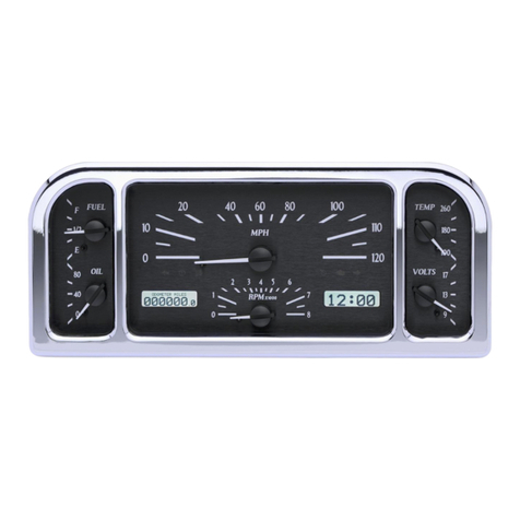
Dakota Digital VHX-1100 User manual

1 MAN #650431B
ACC. POWER
CONST. POWER
GROUND
TACH
WARN
SPD +
SPD SND
SPD -
SPD OUT
SW2 (-)
SW1 (-)
ADJ SND
ADJ -
WTR SND
WTR -
OIL +
OIL SND
OIL -
FUEL +
FUEL SND
FUEL -
WAIT (+)
CRUISE (-)
GEAR (1 WIRE)
4x4 (-)
RIGHT (+)
LEFT (+)
HIGH (+)
BRAKE (-)
CHECK ENG (-)
VHX
CONTROL BOX
CABLE AUX.
I/O
DISPLAY
www.dakotadigital.com
[email protected]
605-332-6513
DIM (+)
ORANGE GREEN
TO REAR OF DISPLAY
VHX
control
box
Operating Manual and Switch Connections for
VHX-1100 & VHX-1200 Systems
The VHX-1100 and VHX-1200 systems have additional display area to provide more functionality. These systems can
display data from any BIM module attached to the system as well as several gauge values from the control box
sensors.
These versions contain four switches in the face which are used as SW1 and SW2 with the use of the switch harness
provided, and SW3 and SW4, which are internal to the VHX system.
SWITCH HARNESS CONNECTION:
Connect the orange wire to SW1 (-) terminal on VHX control box. Upper left switch will be SW1 (speed display).
Connect the green wire to SW2 (-) terminal on VHX control box. Lower left switch will be SW2 (tach display).
Leave the blue wire disconnected (not used). SW3 and SW4 are internal with no additional connections needed.
Upper right switch will be SW3. Lower right switch will be SW4.
VHX-1100 shown below
ORANGE (switch 1)
GREEN (switch 2)
BLUE (switch 3)
2 MAN #650431B
AVAILABLE SCREENS:
The following screens are ONLY available on LCD1 or LCD2 (see main VHX manual for settings):
Message displays Default LCD DESCRIPTION .
ODOMETER 1 Odometer reading (0-999,999)
A MILES 1 Trip A odometer reading (0-9999.9)
B MILES 1 Trip B odometer reading (0-9999.9)
SERVIC (when enabled) 1 Distance to next service (0-9,999, or ---- when past due)
ENGINE 1 Check Engine indicator
BRAKE 1 Brake Warning indicator
4W DRV 1 4 Wheel Drive indication
WAIT 1 Diesel Wait To Start indicator
CLOCK 2 12 hour clock display (press and hold switch to set)
HOURS 2 Hours system has been on with tach signal (0-999.9)
HI SPEED 2 High speed recall (0-255)
0-60 MPH 2 0-60 mph time in seconds (0-25.5)
1/4¼MI SPD 2 Vehicle speed at end of ¼ mile (trap speed)
1/4 MI TIME 2 Time to travel ¼ mile from standing start
HIGH RPM 2 High RPM recall (0-18,000)
volts none Battery voltage (display may be enabled in setup)
In addition to the above screens, LCD1 and LCD2 may display any or all the screens listed below. These
screens are also available for display in LCD3 and LCD4. The main VHX operations manual covers
selecting which screens display in LCD1 and LCD2. See the setup instructions in this manual for selecting
the which screens display in LCD3 and LCD4.
LCD1/LCD2/LCD3/LCD4
Message displays DESCRIPTION .
tachometer Digital tach readout on message display
MPH Digital speed readout on message display
KM/H Digital alternate speed unit conversion
water TEMP Digital engine temp readout on message display
OIL PRESSURE Digital oil pressure readout on message display
FUEL Digital fuel level readout on message display
GEAR (with optional GSS) Gear shift position indicator
Additionally, many other screens may also be available (many of these readings require additional
sensors and or BIM expansion modules) including:
Gear Position Compass Various temperature readings
Various pressure readings More readings may be available from BIM modules
By default all available screens for LCD3 and LCD4 are set to “ON” but only screens with data available
will be displayed.
WARNING POINTS:
Warnings for the main system values (Engine Temp, Oil Pressure, Fuel, and Tachometer) will only be
displayed in LCD1, however, BIM modules that have the internal warning points (set in VHX main
system setup) will flash if they are currently being displayed and they are in a warning condition.
3 MAN #650431B
SETUP
This VHX system has two different setup menus that can be used to configure your VHX system.
The first is the controller setup. The second is the display head setup.
The controller setup allows you to configure how the control box connects to your vehicle, what
senders are used and also allows you to do some setup on many connected expansion modules.
This setup is also used in setting up the display preferences of the primary display areas (LCD1
and LCD2). To enter this setup, press and hold SW1 while turning on the key. Refer to the main
VHX Installation and Operation manual for the various options and settings.
The display head setup allows configuring the two additional display areas (LCD3 and LCD4) that
are not included in standard VHX systems. To enter this setup menu, press and hold SW3 while
turning on the key. Below is a list and description of the setup options for the display head setup.
Main Menu
Sub Menu
Description
Update spd
SLOW
Tach display updates at a slow rate
Med
Tach display updates at a medium rate
FAST
Tach display updates at a fast rate
Temp unit
F
Sets temp displays in LCD3 and LCD4 to Fahrenheit
C
Sets temp displays in LCD3 and LCD4 to Celsius
Altim Unit*
FT
Altimeter display in LCD3 or LCD4 will be in feet
M
Altimeter display in LCD3 or LCD4 will be in meters
Screens
(available screen) 3
Screen can only be displayed in LCD 3
(available screen) 4
Screen can only be displayed in LCD 4
(available screen) 3+4
Screen can be displayed in LCD 3 and/or LCD 4
(available screen) OFF
Screen will not display in LCD 3 or LCD 4
Done
Exit sub menu and return to main menu
Set defaults
Y
Select to put display settings back to default
N
Select to cancel reset to default
Done
--
Exits setup and returns gauge to normal operation
*The “
ALTIM UNIT
” setting only available if altimeter data is being provided by an expansion module such as the
GPS-50-1.
UPDATE SPEED (update spd)
This option sets the update rate of the tachometer when displayed in LCD3 or LCD4. The FAST
setting allows frequent updates so the reading is more accurate at any given time. Faster readings
may be difficult to read or distracting so some customers prefer a slower averaged reading which is
available in the MED or SLOW setting. Default setting is MED.
Enter setup by pressing SW3 and turning key on
Press and Release SW3 until “UPDATE SPD” is displayed, then press and hold SW3.
Press and release SW3 to toggle through speed settings.
Press and hold SW3 when desired setting is displayed to save setting.
“DONE” will be displayed. Release SW3 to return to main menu.
4 MAN #650431B
TEMPERATURE UNIT (TEMP UNIT)
This option sets the unit used to display temperature readings when displayed in LCD3 or LCD4. The two options are
F (Fahrenheit) and C (Celsius). Default setting is F.
Enter setup by pressing SW3 and turning key on
Press and Release SW3 until “TEMP UNIT” is displayed, then press and hold SW3.
Press and release SW3 to toggle units between F or C.
Press and hold SW3 when desired setting is displayed to save setting.
“DONE” will be displayed. Release SW3 to return to main menu.
ALTIMETER UNIT (ALTIM UNIT)
This option sets the unit used to display altimeter readings when displayed in LCD3 or LCD4. This option will only be
available if an expansion module that provides altimeter data (such as the GPS-50-1) is connected to the system. The
two options are FT (Feet) and M (Meters). Default setting is FT.
Enter setup by pressing SW3 and turning key on
Press and Release SW3 until “altim UNIT” is displayed, then press and hold SW3.
Press and release SW3 to toggle units between FT or M.
Press and hold SW3 when desired setting is displayed to save setting.
“DONE” will be displayed. Release SW3 to return to main menu.
SCREEN DISPLAY SELECTION (SCREENS)
This option turns the display of specific screens on or off for LCD3 or LCD4. If the screen is turned “OFF”, it will not be
displayed when moving through screens using SW3 or SW4 in normal operation. This can be helpful to remove
screens from one display zone to make selecting screens you want to view easier. By default, all available screens are
set on for both LCD3 and LCD4.
Enter setup by pressing SW3 and turning key on
Press and Release SW3 until “screens” is displayed, then press and hold SW3.
“LCD3” and “LCD4” are displayed to indicate their postion. Release SW3.
Press and release SW3 to move through the available screens.
Press and hold SW3 on any screen to select it for changes. The setting is highlighted.
Press and release SW3 to change display setting for screen.
Press and hold SW3 when desired setting is displayed to save setting.
Press and release SW3 until “screens Done” is displayed, then press and hold SW3.
“DONE” will be displayed. Release SW3 to return to main menu.
RESET SETTINGS TO DEFAULT (SET DEFAULTS)
This option sets all the settings described above back to the factory defaults.
Enter setup by pressing SW3 and turning key on
Press and Release SW3 until “set defaults” is displayed, press and hold SW3.
Press and release SW3 to toggle between Y (reset) or N (cancel).
Press and hold SW3 when desired option is displayed to select.
“DONE” will be displayed. Release SW3 to return to main menu.
EXIT SETUP (DONE)
This option exits the setup menu. Alternatively the key may be turned off while in main menu.
Press and release SW3 until “Done” is displayed, then press and hold SW3.
“DONE” will be displayed. Release SW3 to return to normal operation.
WARNING: This product can expose you to chemicals including lead, which is known to the State of California to cause
cancer and birth defects or other reproductive harm. For more information go to www.P65Warnings.ca.gov

This manual suits for next models

1

Other Dakota Digital Automobile Accessories manuals

Dakota Digital VHX-87F-PU User manual

Dakota Digital

Dakota Digital VHX-87F-PU User manual

Dakota Digital VHX-68D-STD User manual

Dakota Digital

Dakota Digital VHX-68D-STD User manual

Dakota Digital Retrotech RTX-70C-CAM User manual

Dakota Digital

Dakota Digital Retrotech RTX-70C-CAM User manual

Dakota Digital VFD3-52F User manual

Dakota Digital

Dakota Digital VFD3-52F User manual

Dakota Digital VHX-37F User manual

Dakota Digital

Dakota Digital VHX-37F User manual

Dakota Digital SIM-1-GSXR User manual

Dakota Digital

Dakota Digital SIM-1-GSXR User manual

Dakota Digital VLC-51C User manual

Dakota Digital

Dakota Digital VLC-51C User manual

Dakota Digital VLC-40F User manual

Dakota Digital

Dakota Digital VLC-40F User manual

Dakota Digital LED Tail Lights LAT-NR170 User manual

Dakota Digital

Dakota Digital LED Tail Lights LAT-NR170 User manual

Dakota Digital VHX-50M User manual

Dakota Digital

Dakota Digital VHX-50M User manual

Dakota Digital MCL-7000 Series User manual

Dakota Digital

Dakota Digital MCL-7000 Series User manual

Dakota Digital LED Tail Lights LAT-NR330 User manual

Dakota Digital

Dakota Digital LED Tail Lights LAT-NR330 User manual

Dakota Digital BIM-01-2-MSD User manual

Dakota Digital

Dakota Digital BIM-01-2-MSD User manual

Dakota Digital VHX-1015 User manual

Dakota Digital

Dakota Digital VHX-1015 User manual

Dakota Digital VHX-81D-PU User manual

Dakota Digital

Dakota Digital VHX-81D-PU User manual

Dakota Digital VHX-1200 User manual

Dakota Digital

Dakota Digital VHX-1200 User manual

Dakota Digital BIM-01-2 User manual

Dakota Digital

Dakota Digital BIM-01-2 User manual

Dakota Digital ARC-1000 User manual

Dakota Digital

Dakota Digital ARC-1000 User manual

Dakota Digital LAT-NR271 User manual

Dakota Digital

Dakota Digital LAT-NR271 User manual

Dakota Digital HDX-88C-PU User manual

Dakota Digital

Dakota Digital HDX-88C-PU User manual

Dakota Digital VHX-1023 User manual

Dakota Digital

Dakota Digital VHX-1023 User manual

Dakota Digital LED Tail Lights for 1969 Firebird LAT-NR291 User manual

Dakota Digital

Dakota Digital LED Tail Lights for 1969 Firebird LAT-NR291 User manual

Dakota Digital COMMANDER Series User manual

Dakota Digital

Dakota Digital COMMANDER Series User manual

Dakota Digital VLC-69F-MUS User manual

Dakota Digital

Dakota Digital VLC-69F-MUS User manual

Popular Automobile Accessories manuals by other brands

Black Horse Off Road 8D091016SS installation instructions

Black Horse Off Road

Black Horse Off Road 8D091016SS installation instructions

Racelogic DSP05-M quick start guide

Racelogic

Racelogic DSP05-M quick start guide

Jaeger 21120524 Fitting instructions

Jaeger

Jaeger 21120524 Fitting instructions

SBS 701 installation instructions

SBS

SBS 701 installation instructions

Masterack LOCKING LADDER RACK Assembly instructions

Masterack

Masterack LOCKING LADDER RACK Assembly instructions

Kia E8300-4D050 manual

Kia

Kia E8300-4D050 manual

Fass STK-5500 installation manual

Fass

Fass STK-5500 installation manual

Valeo 850742 Fitting instructions

Valeo

Valeo 850742 Fitting instructions

AVS Bugflector installation instructions

AVS

AVS Bugflector installation instructions

Directed DIRECTECHS TL11 installation guide

Directed

Directed DIRECTECHS TL11 installation guide

RCI 05+ TOYOTA TACOMA FUEL TANK SKID PLATE installation guide

RCI

RCI 05+ TOYOTA TACOMA FUEL TANK SKID PLATE installation guide

GATmatic GA-600S user manual

GATmatic

GATmatic GA-600S user manual

AVENN 005-TH-RRS64 owner's manual

AVENN

AVENN 005-TH-RRS64 owner's manual

Rhino-Rack 570 manual

Rhino-Rack

Rhino-Rack 570 manual

ARB 3450080 Fitting instructions

ARB

ARB 3450080 Fitting instructions

VEVOR 16A-TYPE2 user manual

VEVOR

VEVOR 16A-TYPE2 user manual

travall TDG 1623 Fitting instructions

travall

travall TDG 1623 Fitting instructions

Mennekes AMTRON Professional+ E 7,4 / 22 OPERATING AND INSTALLATION Manual

Mennekes

Mennekes AMTRON Professional+ E 7,4 / 22 OPERATING AND INSTALLATION Manual

manuals.online logo
manuals.online logoBrands
  • About & Mission
  • Contact us
  • Privacy Policy
  • Terms and Conditions

Copyright 2025 Manuals.Online. All Rights Reserved.