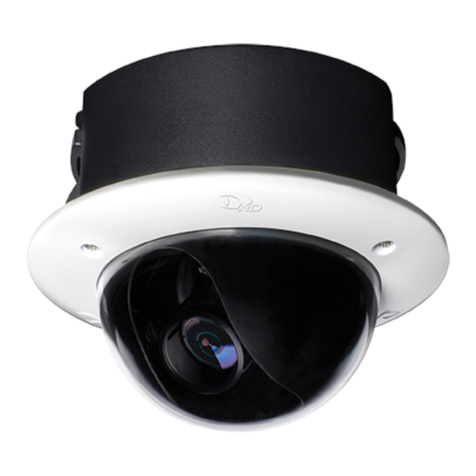
dallmeier DDF4900HDV Series Operating and maintenance instructions

English
Rev. 1.0.3 / 2010-10-27
Installation and Configuration
Vandal-resistant High Definition IP Dome Camera
DDF4500HDV
720p
-SM
(Surface Mount Variant)
-IM
(In-ceiling Mount Variant)
DDF4900HDV
1080p

www.dallmeier.com
© 2010 Dallmeier electronic
The reproduction, distribution and utilization of this document as well as the communication of
its contents to others without express authorization is prohibited. Offenders will be held liable for
the payment of damages. All rights reserved in the event of the grant of a patent, utility model or
design.
We reserve the right to make technical modications.
The manufacturer accepts no liability for damage to property or pecuniary damages arising due
to minor defects of the product or documentation, e.g. print or spelling errors, and for those not
caused by intention or gross negligence of the manufacturer.
Dallmeier electronic GmbH & Co.KG
Cranachweg 1
93051 Regensburg, Germany
www.dallmeier.com
info@dallmeier.com
All trademarks identied by ® are registered trademarks of Dallmeier electronic.
All trademarks identied by *) are trademarks or registered trademarks of the following owners:
Adobe and Flash of Adobe Systems Incorporated headquartered in San José, California, USA
IBM of International Business Machines Corporation headquartered in Armonk, New York, USA
Microsoft, ActiveX, DirectX, Internet Explorer, Windows and Windows Vista of Microsoft Corporation headquartered in Redmond,
Washington, USA
Third-party trademarks are named for information purposes only.
Dallmeier electronic respects the intellectual property of third parties and always attempts to ensure the complete identication of third-party
trademarks and indication of the respective holder of rights. In case that protected rights are not indicated separately, this circumstance is
no reason to assume that the respective trademark is unprotected.

www.dallmeier.com
1.1 Validity .............................................................................................................6
1.2 Documents ......................................................................................................6
1.3 Conventions ....................................................................................................7
3.1 Scope of Delivery ..........................................................................................10
3.2 Transportation and Packaging ......................................................................10
3.3 Appropriate Use ............................................................................................10
3.4 Performance Features ..................................................................................10
3.5 Warranty .......................................................................................................11
3.6 Approvals/Certications ................................................................................11
4.1 General .........................................................................................................12
4.2 Power Supply ................................................................................................12
4.3 Outdoor (Surface Mount Variant only) ..........................................................12
4.4 Operation ......................................................................................................12
5.1 In-ceiling Mount Variant ................................................................................13
5.2 Surface Mount Variant ..................................................................................15
5.3 Camera Module ............................................................................................17
6.1 In-ceiling Mount Variant ................................................................................18
6.2 Surface Mount Variant ..................................................................................23
7.1 System Requirements...................................................................................24
7.2 Connection ....................................................................................................24
7.3 Login .............................................................................................................26
8.1 Language ......................................................................................................28
8.2 System Time .................................................................................................28
8.2.1 Manual Conguration ....................................................................................29
8.2.2 Time Server ..................................................................................................29
8.3 Camera Name...............................................................................................30
8.4 User Management ........................................................................................30
8.4.1 Login Mode ...................................................................................................30
8.4.2 User Groups..................................................................................................31
8.4.3 User ..............................................................................................................32
8.4.3.1 Dene a User ................................................................................................32
8.4.3.2 Edit User .......................................................................................................33
8.4.4 Rights ............................................................................................................33
9.1 Basic Settings ...............................................................................................35
9.1.1 Manual Conguration ....................................................................................36

www.dallmeier.com
9.1.2 DHCP ............................................................................................................36
9.2 Alarm Hosts ..................................................................................................37
9.2.1 Settings .........................................................................................................37
9.2.2 Messages......................................................................................................38
9.2.3 Scheduler ......................................................................................................38
9.2.3.1 Week Timer ...................................................................................................38
9.2.3.2 Exceptions ....................................................................................................40
9.2.3.3 Copy Exceptions ...........................................................................................42
9.2.4 Copy..............................................................................................................43
9.2.5 Delete Alarm Host Entry................................................................................44
9.3 Video Streaming ...........................................................................................45
9.3.1 Transfer Protocol and Format .......................................................................45
9.3.2 Transfer Method ............................................................................................46
9.3.3 TTL ................................................................................................................47
10.1 Video Standard .............................................................................................48
10.2 Sensor...........................................................................................................48
10.2.1 Global............................................................................................................49
10.2.2 Image Optimization .......................................................................................49
10.3 Encoder Settings...........................................................................................50
10.3.1 Encoder 1......................................................................................................50
10.3.2 Encoder 2......................................................................................................52
10.3.3 Encoder 3......................................................................................................52
10.3.4 Audio .............................................................................................................53
11.1 Data Display..................................................................................................54
11.1.1 Filter ..............................................................................................................54
11.1.2 Position .........................................................................................................55
12.1 Activations.....................................................................................................57
12.2 Event Log ......................................................................................................57
12.3 Conguration File ..........................................................................................58
12.3.1 Download ......................................................................................................58
12.3.2 Upload...........................................................................................................58
12.3.2.1 Conguration Recovery ................................................................................59
12.3.2.2 Conguration Transfer to Several Devices ...................................................59
12.4 Info ................................................................................................................61
13.1 Web Browser ................................................................................................62
13.2 RTSP Application ..........................................................................................62
15.1 DC Auto Iris Interface ....................................................................................65
15.2 LAN/PoE .......................................................................................................65
15.3 Audio OUT ....................................................................................................66
15.4 Power IN .......................................................................................................66

www.dallmeier.com
17.1 In-ceiling Mount Variant ................................................................................69
17.2 Surface Mount Variant ..................................................................................70

www.dallmeier.com
This document applies to the following vandal-resistant High Denition IP
dome cameras:
• (in-ceiling mount variant)
• (surface mount variant)
• (in-ceiling mount variant)
• (surface mount variant)
The descriptions in this document are based on the software version and apply to all
above-mentioned device variants.
If text passages require distinctions to be made between the device variants, the complete
product names will be mentioned.
Pictures in this document may differ from the actual product.
The document entitled “Commissioning” contains the most important steps for the connec-
tion and commissioning of the device.
The document entitled “Installation and Conguration” contains detailed descriptions of
the installation, connection, commissioning and conguration of the device. Safety instruc-
tions, general notes and technical data are additionally provided.
The target audience is exclusively specially trained and authorized professionals (install-
ers).

www.dallmeier.com
This document contains various warning words and symbols that indicate potential sources
of danger.
DANGER indicates a hazardous situation which, if not avoided, will result
in death or serious injury.
WARNING indicates a hazardous situation which, if not avoided, could
result in death or serious injury.
CAUTION indicates a hazardous situation which, if not avoided, could
result in minor or moderate injury.
NOTICE indicates practices for preventing property damage, incorrect
congurations or faulty operations.
Instructions are indicated by arrows ().
Expressions in generally indicate a control element on the device (switches or
labels) or on its user interface (buttons, menu entries).
Paragraphs in italics provide information on basic principles, special features and efcient
procedure as well as general recommendations.

www.dallmeier.com
Only use this unit if it is technically in proper working order, to the intended purpose and
while keeping safety and potential dangers in mind.
Installation, mounting, connection, commissioning and conguration of the unit may only
be carried out by qualied personnel. This also applies to the maintenance, testing and re-
pair, whereat the regulations of the DIN VDE 0701 series of standards (repair, modication
and inspection of electrical appliances) must be followed.
The use of video and audio surveillance systems in general is strictly regulated. Inform
yourself about the applicable laws and regulations regarding data, working and environ-
mental protection before using the unit and ensure compliance with them.
Only use internal components that have been tested and approved by Dallmeier. Inappro-
priate internal components can cause malfunctions, damages and data loss and can result
in loss of warranty.
Do not make any modications to the hardware or software that has not been tested and
approved by Dallmeier. Inappropriate modications can cause malfunctions, damages and
data loss and can result in loss of warranty.
Carefully and completely read the documents included in delivery. Always observe the
contained instructions, notes and warnings.
If the unit is brought from a cold to a warm environment, resulting condensation water
can cause malfunctions and damages. In this case wait (up to 8 hours) until the unit has
reached room temperature before commissioning.
Unfavourable operating conditions can shorten the life of the unit and can cause malfunc-
tions, damages and data loss and can result in loss of warranty. Observe the specications
given in the technical data, the operating condition requirements and the maintenance
instructions.
Shocks can cause malfunctions and damages. The unit may not be moved while in opera-
tion.
If objects or liquids get into the unit, immediately disconnect it from the power supply (pull
out the power plug). Contact the sales partner responsible for your area.

www.dallmeier.com
If you notice burnt smell or formation of smoke from the unit, immediately disconnect it from
the power supply (pull out the power plug). Contact the sales partner responsible for your
area.
The housing of the unit may only be opened by qualied personnel for commissioning,
inspection, maintenance and repair.
Disconnect the unit from the power supply. Remove all connected devices. Return the unit
to your respective sales partner.

www.dallmeier.com
Included in the standard scope of delivery is:
1× DDF4900HDV / DDF4500HDV
1× Documentation “Installation and Conguration” (CD)
1× Documentation “Commissioning” (in print)
The scope of delivery may differ depending on the ordered equipment, the device variant
or the country of destination.
The functional range of the device depends on the ordered equipment or device variant
and may differ from this document’s content. Certain functions and features may require an
activation that is subject to costs.
Store the original packaging for transportation at a later date. Dallmeier electronic is not
responsible for damage resulting from unprofessional/improper transportation. The goods
should only be shipped in their original packaging.
If the original packaging is no longer available, ensure that the packaging used sufciently
protects the unit against damage, moisture, heat and cold.
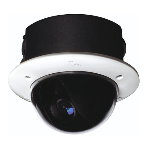
The DDF4900HDV / DDF4500HDV is a vandal-resistant High Denition IP
dome camera. The in-ceiling mount variant is designed for indoor installations in suspend-
ed ceilings, the surface mount variant for indoor installations on ceilings and walls. All de-
vice variants can be operated via PoE (Power over Ethernet, Class 0) or at 12 V DC.
• 1/2.5" 5-Megapixel CMOS image sensor with technology
• Pure Digital Signal Processing
• Light sensitivity at F1.0, 50 IRE: 1.6 lux (in day mode at 720p/1080p)
• Enhanced image quality by means of numerous control functions such as AWB, AGC
and slow shutter
• Resolution: SD, HD (DDF4900HDV: 720p, 1080p, 3MP; DDF4500HDV: 720p, 2MP)
• Frame rate up to 30 fps
• Video compression: H.264, MJPEG
• Simultaneous Dual- or Tri-Streaming
• Megapixel vario lens: F1.8 / f=4 – 10 mm
• Digital Noise reduction
• Hybrid IP camera with analogue video preview output
• Alarm messaging function
• Local video memory: integrated SDHC card slot
• Voltage supply: 12 V DC or PoE

www.dallmeier.com
• Tri-axial adjustment
• Two available device variants: in-ceiling and surface mount variant
• Compact, vandal-resistant housing with IP67 (surface mount variant only)
• DIN EN 50130-4 compliant
For detailed information see chapter “Technical Data” on page 67.
The terms and conditions valid at the signing of the contract shall apply.
Following approvals/certications were valid at the time of document compilation.
Refer to www.dallmeier.com for possible updates.
• CE
• DIN 50130-4 compliant

www.dallmeier.com
Unfavourable local conditions may shorten the life of the product and can cause malfunc-
tions or damages.
Do not install/operate the device in places
• with large scale dust and dirt.
• with steam or oil vapours (e.g. kitchen).
• with direct sunlight.
• strong heat emission (e.g. radiator).
• with improper ambient temperatures.
• near sources of strong radiation (e.g. radio transmitters, magnetic elds).
• with corrosive surroundings (e.g. gases, salt water).
• insufcient air ventilation (e.g. closed cabinet).
The device can be operated via PoE (Power over Ethernet, Class 0) or at 12 V DC.
Ensure that the existing network supports the PoE standard IEEE 802.3af if you want
to supply the device with power over Ethernet.
For outdoor installations (surface mount variant only), use only IP67 approved components
and assemblies (e.g. sealing rings, cable gland).
To extend the product life cycle, protect the device from direct inuence of weather condi-
tions (rainfall, insolation).
Therefore, we recommend a protected installation site (e.g. under a projecting roof).
Observe the following notes for the operation of the device:
• If the device or the cables connected to the device are located near sources of strong
radiation, the video image may be distorted.
• The device is equipped with automatic gain control (AGC). In low light the image may
be altered (e.g. noise). This is not a malfunction.
• The quality of the video image depends on the lens, the lighting and the used moni-
tor.
• Automatic white balance depends on the lighting used and can cause colour distor-
tions in articial light.
• Poor lighting can lead to faulty white balance.

www.dallmeier.com
Thread for M6 screw eye bolt
Housing
Trim ring with bubble
3-axis mount
(pan / tilt / rotation)
Thread for PG16 cable gland
Lens
Ceiling clamp
Housing screw
(T20 Torx)
Fig. 5-1

www.dallmeier.com
M4 locking screw
(ceiling clamp)
M4 locking screw
(ceiling clamp)
Thread for PG16 cable gland
DC auto iris interface
for iris control
Cable fastener Cable fastener
Video preview output
(BNC, CVBS)
Locking screw
(focal length)
Locking screw
(focus)
Thread for
housing screw
Thread for
housing screw
Thread for
housing screw
Camera module
Fig. 5-2 Housing (top view)

www.dallmeier.com
Thread for
PG16 cable gland
Mounting hole for
Ø 4 mm screw
Housing base
Housing with bubble
Housing screw
(T20 Torx)
Lens
3-axis mount
(pan / tilt / rotation)
Fig. 5-3

www.dallmeier.com
Mounting hole for
Ø 4 mm screw
Mounting hole for
Ø 4 mm screw
Mounting hole for
Ø 4 mm screw
DC auto iris interface
for iris control
Cable fastener Cable fastener
Video preview output
(BNC, CVBS)
Locking screw
(focal length)
Locking screw
(focus)
Thread for PG16 cable gland
Camera module
Thread for
housing screw
Thread for
housing screw
Thread for
housing screw
Fig. 5-4 Housing base (top view)

www.dallmeier.com
LAN / PoE
(RJ45 jack)
DC auto iris interface
for iris control
Locking screw
(rotation, z-axis)
Audio OUT
(3.5 mm phone jack)
Power IN
(12 V DC)
SDHC card*
Locking screw
(rotation, z-axis)
*Not included in the standard scope of delivery.
3-axis mount
(pan / tilt / rotation)
Fig. 5-5

www.dallmeier.com
Installation and commissioning of the unit may only be carried out by qualied personnel.
Danger of death or serious injury to the head
Observe the manufacturer’s instructions about the maximum adequate
carrying capacity of the supporting structure and the suspended ceiling
or ceiling tiles.
Use screws suitable for the ceiling/wall material.
Use the correct type of anchor for your ceiling/wall type:
• Plastic screw anchors for solid wall material (concrete/brick)
• Toggle bolt style anchors for drywall / hollow wall type (plaster)
Danger of death or serious injury
Disconnect the power supply unit from the mains socket before connect-
ing the device.
In order to comply with the UL requirements, you have to use a UL-certied, limited power
source (LPS) Class 2 power supply unit.
You need:
• Drywall utility saw or jigsaw
• M6 screw eye bolt
• T20 torx wrench
• Ceiling hook
• Safety wire
• Carabiner
• Phillips screwdriver (M4)

www.dallmeier.com
Cut a circular recess (Ø 143 mm) in the suspended ceiling using a drywall utility saw or
a jigsaw.
Screw the M6 screw eye bolt on the bottom side of the housing.
Unscrew the 3 housing screws using a T20 torx wrench and remove the trim ring.
Suspended ceiling
Ø 143 mm
M6 screw eye bolt
Ceiling clamp
Trim ring with bubble
PG16 cable gland
Housing screw
(T20 Torx)
Fig. 6-1

www.dallmeier.com
Screw a ceiling hook on the supporting structure.
Attach the safety wire to the M6 screw eye bolt (use a carabiner) and the ceiling hook.
Run the required cables suspended from the ceiling through a PG16 cable gland.
Screw the PG16 cable gland in the appropriate thread of the housing.
Insert the housing into the circular recess.
Carabiner
Safety wire
Supporting structure
Ceiling hook
Suspended ceiling
Ceiling clamp
PG16 cable gland
M6 screw eye bolt
Fig. 6-2
This manual suits for next models
5
Table of contents
Other dallmeier IP Camera manuals

dallmeier
dallmeier DF5250HD-DN/IR Guide

dallmeier
dallmeier DDF4820HDV-DN-IM Guide

dallmeier
dallmeier DF3000IP Operating and maintenance instructions

dallmeier
dallmeier DDF5 50HDV-DN-IM Series Guide

dallmeier
dallmeier DF5 00HD-DN/IR Series User manual

dallmeier
dallmeier DF4820HD-DN Guide

dallmeier
dallmeier DF5400HD-DN/IR Guide

dallmeier
dallmeier DDF51 HDV-DN-SM Series Guide

dallmeier
dallmeier DF5200HD-DN/IR Guide

dallmeier
dallmeier DF4 20HD-DN/IR Series Guide