manuals.online logo
Brands
  1. Home
  2. •
  3. Brands
  4. •
  5. ELRO
  6. •
  7. Security System
  8. •
  9. ELRO AS80SR11A User manual

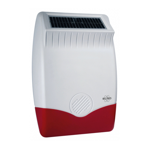
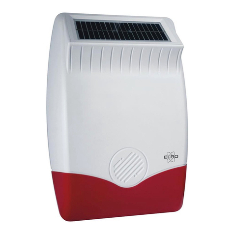
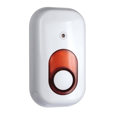
ELRO AS80SR11A User manual

Other ELRO Security System manuals

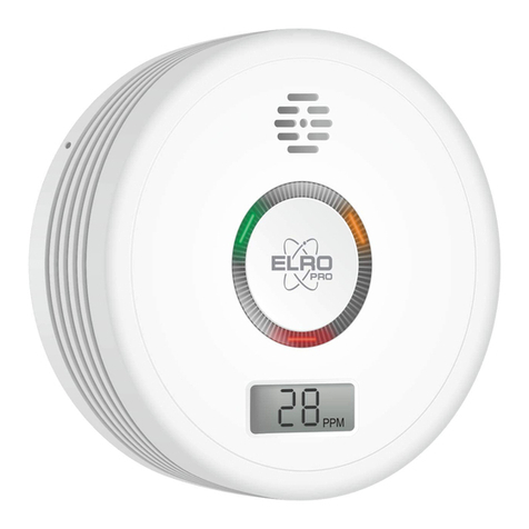
ELRO ARD51 User manual

ELRO

ELRO ARD51 User manual

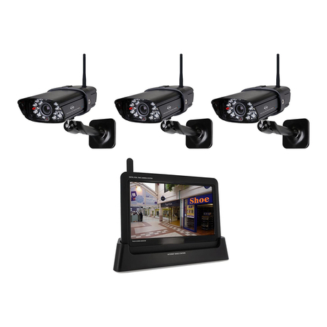
ELRO DWH SERIES Instruction Manual

ELRO

ELRO DWH SERIES Instruction Manual

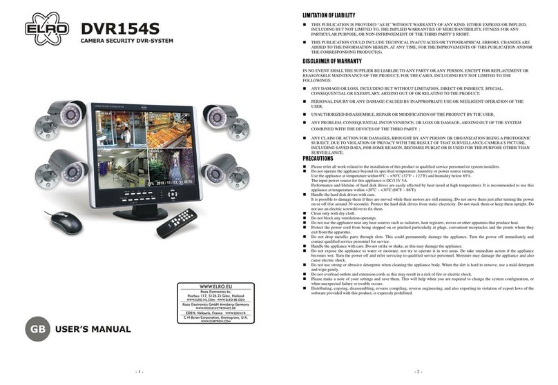
ELRO DVR154S User manual

ELRO

ELRO DVR154S User manual

ELRO AS80SR11B User manual

ELRO

ELRO AS80SR11B User manual

ELRO FR350111R User manual

ELRO

ELRO FR350111R User manual

ELRO CZ60RIP11S User manual

ELRO

ELRO CZ60RIP11S User manual

ELRO DWH SERIES Service manual

ELRO

ELRO DWH SERIES Service manual

ELRO CBFS58R-01 User manual

ELRO

ELRO CBFS58R-01 User manual

ELRO AG40SR11A User manual

ELRO

ELRO AG40SR11A User manual

ELRO DVR158S User manual

ELRO

ELRO DVR158S User manual

ELRO AS90SRB User manual

ELRO

ELRO AS90SRB User manual

ELRO HIS20USB User manual

ELRO

ELRO HIS20USB User manual

ELRO CZ60RIP11S Service manual

ELRO

ELRO CZ60RIP11S Service manual

ELRO HIS20S Installation instructions

ELRO

ELRO HIS20S Installation instructions

ELRO FC5003 User manual

ELRO

ELRO FC5003 User manual

ELRO C901 User manual

ELRO

ELRO C901 User manual

ELRO AS90S User manual

ELRO

ELRO AS90S User manual

ELRO AS800011 User manual

ELRO

ELRO AS800011 User manual

ELRO PRO AP55SR11B User manual

ELRO

ELRO PRO AP55SR11B User manual

ELRO CS87T User manual

ELRO

ELRO CS87T User manual

ELRO AG400011 User manual

ELRO

ELRO AG400011 User manual

ELRO AG400011 User manual

ELRO

ELRO AG400011 User manual

ELRO Pro Alarm System AP5500 User manual

ELRO

ELRO Pro Alarm System AP5500 User manual

ELRO PK4910 User manual

ELRO

ELRO PK4910 User manual

Popular Security System manuals by other brands

Polon-Alfa 4000 Installation and maintenance manual

Polon-Alfa

Polon-Alfa 4000 Installation and maintenance manual

Nexcom NViS 14162 Series user manual

Nexcom

Nexcom NViS 14162 Series user manual

Eminent EM8670 Quick install

Eminent

Eminent EM8670 Quick install

urmet domus alpha 1060 INSTALLATION AND USE BOOKLET

urmet domus

urmet domus alpha 1060 INSTALLATION AND USE BOOKLET

SmartPool YardGuard YG03 manual

SmartPool

SmartPool YardGuard YG03 manual

DSC PC5964 Mounting instructions

DSC

DSC PC5964 Mounting instructions

Secure USAB-1 operating instructions

Secure

Secure USAB-1 operating instructions

B&B 480 SERIES Operation & maintenance manual

B&B

B&B 480 SERIES Operation & maintenance manual

ADEMCO VISTA-20P Series Installation and setup guide

ADEMCO

ADEMCO VISTA-20P Series Installation and setup guide

Inner Range Concept 2000 user manual

Inner Range

Inner Range Concept 2000 user manual

Johnson Controls PENN Connected PC10 Install and Commissioning Guide

Johnson Controls

Johnson Controls PENN Connected PC10 Install and Commissioning Guide

Aeotec Siren Gen5 quick start guide

Aeotec

Aeotec Siren Gen5 quick start guide

Swann SW-P-MC2 Specifications

Swann

Swann SW-P-MC2 Specifications

Ecolink Siren+Chime user manual

Ecolink

Ecolink Siren+Chime user manual

EDM Solution 6+6 Wireless-AE installation manual

EDM

EDM Solution 6+6 Wireless-AE installation manual

Siren LED GSM operating manual

Siren

Siren LED GSM operating manual

Detection Systems 7090i Installation and programming manual

Detection Systems

Detection Systems 7090i Installation and programming manual

FRIEDLAND MA10 Installation and operating instructions

FRIEDLAND

FRIEDLAND MA10 Installation and operating instructions

manuals.online logo
manuals.online logoBrands
  • About & Mission
  • Contact us
  • Privacy Policy
  • Terms and Conditions

Copyright 2025 Manuals.Online. All Rights Reserved.

1
AS80SR11A
Voice Siren
Installation Instructions
General Introduction
The Voice Siren is a two-way wireless alarm device which functions not only
as a siren, but also a strobe light with voice indicator functions.
Includes the following functions:
*
Tamperproofprotection
*
Green and red flashing strobe light
*
Visual and audible alarmindications
*
6 indicating beep sounds for identification
*
EEPROM for non-volatile memory facility
*
LED for identification, visual command confirmation and batterystatus
Product Layout
Keys
A. Speaker
E. Tamper Switch
B. Voice Speaker
F. Learning Key
C. Backplate screws
G. Micro USB (Factory use only)
D. Backplate
H. DC Jack
Functions
A. Siren Speaker
Siren Warning 110 dB
B. Voice Speaker
Voice Indicator 90 dB
E. Tamper Jumper Link
A full alarm condition will be enabled when the device is
removed from the wall.
F. Learning Key
Learn and clear ID codes.
G. Micro USB
Update voice messages through the USB cable. (Factory
use only)
H. DC Jack
Socket for connecting DC adapter
Binding
1.
Loosen and remove the locking screw from the bottom edge of the unit
counter clockwise.
2.
Slide the backplate out of theunit.
Figure 1 Front View
Figure 3 Back View
Figure 2 Under View
Figure 4 Inside View
3.
Prepare four 1.5V alkaline batteries. Do not insert them into the unityet.
4.
Log into the Homesys account from a webbrowser.
2
5.
Select “System”, then “Add aDevice”,
6.
Select “VoiceSiren”.
7.
The following screen will appear. This means the gateway is entering
binding mode.
8.
Insert the batteries with correct polarity at thispoint.
9.
The screen below will appear in 10 seconds if the process issuccessful.
10.
Time-out will occur if the binding process was unsuccessful. Please check
“Manual Binding”.
3
Manual Binding
1.
Repeat steps 6 to 8 of the Binding with ELRO Smart Home Alarmsection.
2.
Press and hold the learning key “F” (as shown in Figure 4) for more than 3
seconds until the green strobe LED turns off, then quickly release the
learning key. The Green LED will flash repeatedly. This implies it has now
entered the binding mode and is waiting to receive binding signals from
thegateway.
3.
Within 5 seconds the green LED will stop flashing indicating the learning
procedure is completed. The screen below will appear indicating the
process is successful.
Testing
AS80SR11A can be tested with ELRO Smart Home Alarm smartphone App
by changing the security mode between ARM and DISARM on the App and
the listening for voice indication from AS80SR11A
If there is no response please check the “Troubleshooting”.
Mounting
It should be mounted inside the building in a position that is clearly visible and
at a height which is relatively inaccessible to an intruder. It is also suggested
not to mount the unit in the basement to avoid poor transmission.
1.
Use the backplate as a template to mark and drill the position of 3 mounting
holes on the wall. Fix the backplate to the wall using the plastic wall plugs and
fixing screws provided.
2.
Slide the unit down to the backplate and fasten the locking screw clockwise.
4
Tamper Protection
Tamper switch is set inside the housing to prevent it from being forcibly
removed from the wall. Removing the unit from backplate will release the
tamper switch and generate a full alarm condition.
Install Power Adapter (Optional)
The power adapter is an optional accessory. An optional 600mA @ 6V DC
power adapter can be purchased if needed. A cable track is set inside the unit
for you to secure the power adapter. Please install the power adapter as
follows:
Maintenance
*
Do not immerse this unit in water or any otherliquid.
*
Four 1.5V Alkaline LR14 batteries are supplied. When batteryis low, a red
LED will flash every 30 seconds. When this situation occurs, replace the
batteries as soon as possible.
Troubleshooting
The troubleshooting table lists some possible causes and solutions. Please
contact your original retailer or nearest service center if the below solutions
cannot solve your problem.
Symptom
Possible Cause
Recommendation
LED indicator stops
displaying
No battery is inserted or
battery is flat
Check if 4 batteries are inserted
properly
Failure
Send the unit to the service
center and do not open it
The display function of
LED indicator is
operating properly, but
the siren doesn’t
respond to alerts and
system changes.
1.The binding process
has failed
2.The siren cannot
communicate with the
gateway.
1.Please follow theinstructions
for Manual binding.
2.Place the siren closer to the
gateway.
Reset to factory default:
To reset AS80SR11A back to factory default state:
1.
Insert the batteries into theunit
2.
Press and hold the learning key “F” (as shown in Figure 5) for more than 3
seconds until the green strobe LED turns off, then release the learning key.
The Green LED will flash repeatedly. This implies it has now entered
binding mode and is waiting to receive binding signals from thegateway.
3.
Press and hold the learning key for more than 6 seconds and release
within 30 seconds, during which it will sound every 0.5 seconds with green
LED turned on. The learning procedure is completed when a longer beep
tone has sounded and the LED will flash orange every 2seconds.
Specifications
Power adaptor (option)
600 mA@6V DC
Battery Type
1.5V LR14 x 4
Battery Life
About one year in standby mode at 25°C
Operating Frequency
868MHz
** Specifications are subject to change and improvement without notice.
2.
Route the cable along the
cable track.
1.
Connect the plug of
power adapter to the DC
jack inside the unit.