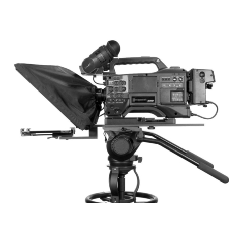
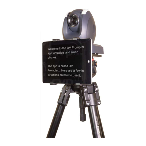
Data Video TP-700 User manual

ENG TELEPROMPTER KIT TP-700
0
Instruction Manual
ENG & Freestanding
TP-700
TELEPROMPTER KIT

ENG & FREESTANDING TELEPROMPTER KIT TP-700
2
Contents
CONTENTS .................................................................................................................................................................... 2
FCC COMPLIANCE STATEMENT ..................................................................................................................................... 4
WARNINGS AND PRECAUTIONS.................................................................................................................................... 4
GLASS –HANDLE WITH CARE .................................................................................................................................................. 4
WARRANTY .................................................................................................................................................................. 5
STANDARD WARRANTY........................................................................................................................................................... 5
REGISTER FOR 3YEAR WARRANTY............................................................................................................................................. 5
DISPOSAL ............................................................................................................................................................................. 5
PACKING LIST........................................................................................................................................................................ 6
PRODUCT OVERVIEW ................................................................................................................................................... 8
FEATURES............................................................................................................................................................................. 8
ASSEMBLY –TP-700 ...................................................................................................................................................... 9
ASSEMBLY –ENG CONFIGURATION ........................................................................................................................................... 9
ASSEMBLY –FREESTANDING CONFIGURATION ........................................................................................................................... 13
ASSEMBLY –OPTIONAL TALENT MONITOR ............................................................................................................................... 17
CONNECT A PC/LAPTOP FOR CONTROL AND MONITORING OVER IP ...........................................................................18
DIRECT ETHERNET CONNECTION.............................................................................................................................................. 18
CONNECTION VIA A ROUTER /DHCP LAN................................................................................................................................ 18
CAMERA EXPOSURE AND THE 70/30 MIRROR GLASS...................................................................................................20
CLEANING THE 70/30 GLASS ........................................................................................................................................20
OPTIONAL TELEPROMPTER REMOTE CONTROLS .........................................................................................................21
WR-500 HANDHELD CONTROLLER ......................................................................................................................................... 21
Control Buttons ........................................................................................................................................................... 22
Remote Accessories .................................................................................................................................................... 22
Lanyard Necklace........................................................................................................................................................ 22
CR2032 Battery ........................................................................................................................................................... 23
FS-30 FOOT SWITCH............................................................................................................................................................ 24
Control Buttons ........................................................................................................................................................... 24
GENERIC PRESENTATION CLICKERS .......................................................................................................................................... 25
Control Buttons ........................................................................................................................................................... 25
DVPROMPTER PLUS APP..............................................................................................................................................26
DOCUMENTS SCREEN ........................................................................................................................................................... 26
CREATING AND EDITING TEXT SCRIPTS AND SLIDES ..................................................................................................................... 27
Text Scripts.................................................................................................................................................................. 27
Slides ........................................................................................................................................................................... 27
REAL TIME EDITING......................................................................................................................................................... 32
PLAYLISTS........................................................................................................................................................................... 33
Adding a script to the playlist ..................................................................................................................................... 33
Changing the playlist order......................................................................................................................................... 33
CONTROL ........................................................................................................................................................................... 34
Via the device (USB mouse) ........................................................................................................................................ 34
Via the web interface.................................................................................................................................................. 35
Using Optional Hardware Remote Controls................................................................................................................ 36
MENU BAR......................................................................................................................................................................... 37
Settings ....................................................................................................................................................................... 38
Network ...................................................................................................................................................................... 40
ENG & FREESTANDING TELEPROMPTER KIT TP-700
3
SYNCHRONIZING MULTIPLE DEVICES........................................................................................................................................ 42
Via HDMI..................................................................................................................................................................... 42
Via Ethernet ................................................................................................................................................................ 42
CONNECTING AN EXTERNAL DISPLAY ....................................................................................................................................... 44
UPDATING THE APP.............................................................................................................................................................. 45
SPECIFICATIONS...........................................................................................................................................................47
SERVICE AND SUPPORT ...............................................................................................................................................48
Disclaimer of Product and Services
The information offered in this instruction manual is intended as a guide only. At all times, Datavideo Technologies will try
to give correct, complete and suitable information. However, Datavideo Technologies cannot exclude that some information
in this manual, from time to time, may not be correct or may be incomplete. This manual may contain typing errors, omissions
or incorrect information. Datavideo Technologies always recommend that you double check the information in this document
for accuracy before making any purchase decision or using the product. Datavideo Technologies is not responsible for any
omissions or errors, or for any subsequent loss or damage caused by using the information contained within this manual.
Further advice on the content of this manual or on the product can be obtained by contacting your local Datavideo Office or
dealer.

ENG & FREESTANDING TELEPROMPTER KIT TP-700
4
FCC Compliance Statement
This device complies with part 15 of the FCC rules. Operation is subject to the following two conditions:
1. This device may not cause harmful interference, and
2. This device must accept any interference received, including interference that may cause undesired
operation.
Warnings and Precautions
1. Read all of these warnings and save them for later reference.
2. Follow all warnings and instructions marked on this unit.
3. Unplug this unit from the wall outlet before cleaning. Do not use liquid or aerosol cleaners. Use a damp
cloth for cleaning.
4. Do not use this unit in or near water.
5. Do not place this unit on an unstable cart, stand, or table. The unit may fall, causing serious damage.
6. Slots and openings on the cabinet top, back, and bottom are provided for ventilation. To ensure safe and
reliable operation of this unit, and to protect it from overheating, do not block or cover these openings. Do
not place this unit on a bed, sofa, rug, or similar surface, as the ventilation openings on the bottom of the
cabinet will be blocked. This unit should never be placed near or over a heat register or radiator. This unit
should not be placed in a built-in installation unless proper ventilation is provided.
7. This product should only be operated from the type of power source indicated on the marking label of the
AC adapter. If you are not sure of the type of power available, consult your Datavideo dealer or your local
power company.
8. Do not allow anything to rest on the power cord. Do not locate this unit where the power cord will be walked
on, rolled over, or otherwise stressed.
9. If an extension cord must be used with this unit, make sure that the total of the ampere ratings on the
products plugged into the extension cord do not exceed the extension cord rating.
10. Make sure that the total amperes of all the units that are plugged into a single wall outlet do not exceed 15
amperes.
11. Never push objects of any kind into this unit through the cabinet ventilation slots, as they may touch
dangerous voltage points or short out parts that could result in risk of fire or electric shock. Never spill liquid
of any kind onto or into this unit.
12. Except as specifically explained elsewhere in this manual, do not attempt to service this product yourself.
Opening or removing covers that are marked “Do Not Remove” may expose you to dangerous voltage
points or other risks, and will void your warranty. Refer all service issues to qualified service personnel.
13. Unplug this product from the wall outlet and refer to qualified service personnel under the following
conditions:
a. When the power cord is damaged or frayed;
b. When liquid has spilled into the unit;
c. When the product has been exposed to rain or water;
d. When the product does not operate normally under normal operating conditions. Adjust only those
controls that are covered by the operating instructions in this manual; improper adjustment of other
controls may result in damage to the unit and may often require extensive work by a qualified technician
to restore the unit to normal operation;
e. When the product has been dropped or the cabinet has been damaged;
f. When the product exhibits a distinct change in performance, indicating a need for service.
GLASS –Handle with care
This product contains a sheet of 70/30 mirror glass please handle it with care.
To avoid a risk of damage or injury please follow this instruction manual and use caution
when transporting, un-packing, cleaning, assembling or dis-assembling this part of the
product.

ENG & FREESTANDING TELEPROMPTER KIT TP-700
5
Warranty
Standard Warranty
Datavideo equipment are guaranteed against any
manufacturing defects for one year from the date of
purchase.
The original purchase invoice or other documentary
evidence should be supplied at the time of any
request for repair under warranty.
The product warranty period begins on the purchase
date. If the purchase date is unknown, the product
warranty period begins on the thirtieth day after
shipment from a Datavideo office.
All non-Datavideo manufactured products (product
without Datavideo logo) have only one year warranty
from the date of purchase.
Damage caused by accident, misuse, unauthorized
repairs, sand, grit or water is not covered under
warranty.
Viruses and malware infections on the computer
systems are not covered under warranty.
Any errors that are caused by unauthorized third-
party software installations, which are not required by
our computer systems, are not covered under
warranty.
All mail or transportation costs including insurance
are at the expense of the owner.
All other claims of any nature are not covered.
All accessories including headphones, cables, and
batteries are not covered under warranty.
Warranty only valid in the country or region of
purchase.
Your statutory rights are not affected.
Register for 3 year Warranty
All Datavideo products purchased after July 1st,
2017 are qualified for a free two years extension to
the standard warranty, providing the product is
registered with Datavideo within 30 days of
purchase.
Certain parts with limited lifetime expectancy such as
LCD panels, DVD drives, Hard Drive, Solid State
Drive, SD Card, USB Thumb Drive, Lighting, Camera
module, PCIe Card are covered for 1 year.
The three-year warranty must be registered on
Datavideo's official website or with your local
Datavideo office or one of its authorized distributors
within 30 days of purchase.
Disposal
For EU Customers only - WEEE Marking
This symbol on the product or on its packaging indicates that this product must not be disposed of with
your other household waste. Instead, it is your responsibility to dispose of your waste equipment by
handing it over to a designated collection point for the recycling of waste electrical and electronic
equipment. The separate collection and recycling of your waste equipment at the time of disposal will help
to conserve natural resources and ensure that it is recycled in a manner that protects human health and
the environment. For more information about where you can drop off your waste equipment for recycling,
please contact your local city office, your household waste disposal service or the shop where you
purchased the product.
CE Marking is the symbol as shown on the left of this page. The letters "CE" are the abbreviation of
French phrase "Conformité Européene" which literally means "European Conformity". The term initially
used was "EC Mark" and it was officially replaced by "CE Marking" in the Directive 93/68/EEC in 1993.
"CE Marking" is now used in all EU official documents.

ENG TELEPROMPTER KIT TP-700
6
Packing List
Item
Description
Quantity
A
Main TP-700 ENG prompter rail
1
B
Smaller rail with spacer block for mounting item F
1
C
¼” Screws Length 27mm secures item Aor AA to B
2
D1
Hex Tool (Silver) for counter sunk Hex head screws
1
D2
Hex Tool (Silver) for Glass Frame Hex screws
1
D3
Hex Tool (Silver) for VESA Hex screws
1
E
16mm ¼ screws with washer to attach item F to item B
(With red dot)
2
F
15” LCD control unit
1
G
Glass frame with 4 Velcro straps
1
H
Wing nut screws ¼” Length 19mm secures item A or AA to
G
2
I
Cloth Snood/Hood with Velcro straps
1
J
70/30 Glass sheet with Green and Red stickers
1
K
Snood/Hood support wire
1
L
¼” Camera securing screws length 16mm
2
M
¼” Camera securing screws length 31mm
2
N
Camera riser block 15mm thick
1
O
USB Mouse
1
P
Adapter screw to convert 3/8” hole to ¼” hole
1
Q
¼” Counter sunk hex head screw length 16mm
1
R
¼” Counter sunk hex head screw length 31mm
1
S
Talent monitor vertical mounting rail
1
T
Talent monitor VESA adapter plate
1
U
14mm M4 screws for mounting 75MM VESA monitors
4
V
Universal mains PSU
1
W
Ethernet Cable 5M
1
X
3.5mm input adapter for WR-500 remote control
1
Y
12V D-Tap Cable
1
Z
12mm M4 Screws to secure item J
2
AA
Small rail to attached item G to B in a freestanding
configuration
1
BB
16MM M4 screw to attach item S to item B
2
CC
8mm M4 screws for mounting item T
4
CCC
12mm M4 screws for mounting item 100MM VESA
monitors
4

ENG & FREESTANDING TELEPROMPTER KIT TP-700
7
NOTE: Depending on your order, your TP-700 kit could have been supplied with one of a range of remote controls
–for more information on the remote controls please speak with your local Datavideo supplier or check our
website www.datavideo.info for details.

ENG & FREESTANDING TELEPROMPTER KIT TP-700
8
Product Overview
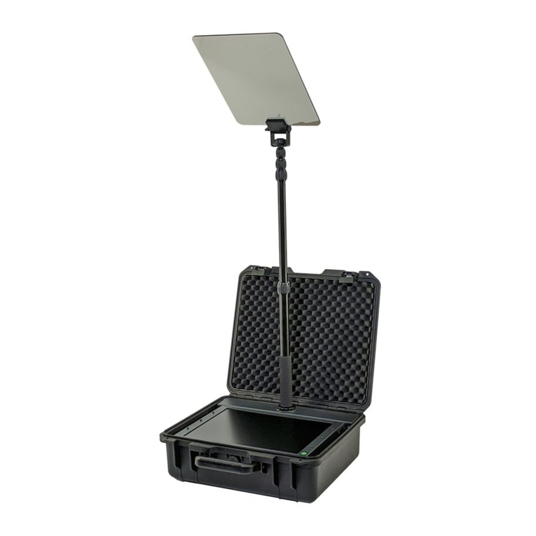
Studio teleprompter with extra-large trapezoid glass. TP-
700 features a bright 15” LCD screen with dvPrompter Plus
app built-in. There is no need to run software on a laptop.
The Datavideo Prompter Kit, TP-700, can be used with
ENG style cameras, where the camera is mounted directly
to the teleprompter rig, or with any camera in its
freestanding configuration.
Prepared scripts or cue sheets can be easily copied and
pasted into the dv Prompter Plus app software and scrolled
at a set automatic rate or controlled by a user with the
optional wired / wireless remote for a more natural result. A
number of clear fonts, colours and text sizes are available
making reading comfortable from a variety of distances.
Features
ENG and Freestanding configurations
dvPrompter Plus software built in
Can be powered by the mains or a V-Lock
battery
HDMI input and HDMI output can be used to
connect multiple TP-700s together
The HDMI input also allows the built-in tablet to
be used as a HDMI monitor with third party
software if required
Fully controllable via Ethernet
Supports up to 19” talent monitor on the front,
VESA 75 and 100 mounts
An optional wired remote control and foot pedal
is available
Can also be controlled using standard wireless
presentation remotes

ENG & FREESTANDING TELEPROMPTER KIT TP-700
9
Assembly –TP-700
Assembly –ENG Configuration
1. Attach/screw the tripod’s own quick release plate
to the screw holes on the base of the TP-700
ENG Prompter rail, item A.
The long slot will be to the rear of the camera
position and the four holes in the rail will be
towards the lens of the camera.
2. Now slide and secure the tripod plate, with
prompter rail, item A, onto the head of the tripod
or dolly.
3. Use the hand screws item C, to secure the lower
part of the ENG Prompter Frame item B in place
using the counter sunk holes in the main part of
the frame item A.
Note: There should be two holes left free in front
of this mounting position for the Glass frame.
4. There are four adhesive Velcro straps packed
inside the Snood/Hood, item I. Peel off the white
paper backing before applying these straps to
the Glass Frame, item G.
Apply the two long Velcro strips to the Glass
Frame edges on the Left side and Right side.
Then apply the two smaller Velcro strips to the
Bottom Left and Right sides of the Glass Frame
edge.
Be careful not to cover any screws and keep
them straight.

ENG & FREESTANDING TELEPROMPTER KIT TP-700
10
5. Slide the Glass frame, item G, on to the front of
the TP-700 ENG prompter rail, item A. Ensure the
upper part of the Glass Frame, Item G, is leaning
away from the camera position and secure with
the two wing nut screws, item H.
6. There are two slots on the inside left and right of
the Glass Frame, Item G. Guide/slide 70/30
Mirror Glass sheet, item J, into these slots from
above.
The Red circle sticker on the Mirror Glass, item
J, should be facing camera position / lens.
The Green circle sticker on item J should be
facing toward the on screen talent /
commentator.
7. Optionally, secure the glass sheet within the frame
using the small M4 screws, Item Z, at the top of
each frame slot. The hex tool, item D2 can be
used to tighten the screws.
8. Fit the 15” LCD control unit, Item F, to the lower part of the ENG Prompter Frame item B using the ¼ thumb
screws, Item E. Ensure the LCD control unit has the red power button facing the front of the TP-700.
9. Decide if you need to use the TP-700 MKII ENG
camera riser block or not.
Ideally you want the lens of your camera
positioned as close to the centre of the 70/30
mirror glass as possible.
In some cases depending on your camera and its
ENG camera plate the camera lens may already
be high enough.

ENG & FREESTANDING TELEPROMPTER KIT TP-700
11
Tripod adapter plate shown
without riser block
10. Secure the ENG tripod adapter plate (not
supplied) and riser block item N (if required) to
the prompter rail item A using two of the riser
screws provided, items L or M. These screws go
through the long slot on the riser block and
prompter rail and into the base of the tripod
adapter plate.
Two screw sets are provided, the long set (Item
M31mm long) is for when using the riser block.
The short set (Item L 16mm long) when just
using the camera plate on its own.
Items Q and R are provided in case the tripod
adapter plate and riser block need to be
positioned over the tripod head.
11. You can now mount the ENG camera to the
tripod adapter plate. Take care to protect the
camera lens and the 70/30 mirror glass. If
necessary slide everything further along the
prompter frame.
The tip of the lens should be about 1 to 2 cm
away from the centre of the 70/30 Mirror Glass.
It may be a good idea to remove the lens
sun hood if this is possible.
12. Fit the Snood / Hood support wire, item K.. This
stops the cloth Snood / Hood from dipping in front
of the camera lens. There are two sets of holes
in the glass frame for this Snood / Hood support
wire.
13. Fit the cloth Snood /Hood, item I, around the lens
and to the Glass Frame edges, item G. The
Velcro strips marry the Snood/Hood to the Glass
Frame.

ENG & FREESTANDING TELEPROMPTER KIT TP-700
12
14. Pull the draw cord to secure the cloth Snood /
Hood, item I, around the camera lens and to shut
out light from the camera side.
15. Turn on the 15” LCD control unit by connecting the mains power supply, Item V or connecting V-Lock battery using
the D-Tap cable, Item Y. The dvPrompter Plus software will automatically load, please see the appropriate section
of this manual for detailed software usage instructions.
16. If required adjust the position of the 15” LCD control unit.
17. Adjust the camera exposure settings as necessary. See the Camera Exposure section of this manual.

ENG & FREESTANDING TELEPROMPTER KIT TP-700
13
Assembly –Freestanding configuration
1. Use the hand screws item C, to secure the lower
part of the ENG Prompter Frame item B in place
using the counter sunk holes in the freestanding
rail item AA.
Note: There should be two holes left free in front
of this mounting position for the Glass frame.
2. There are four adhesive Velcro straps packed
inside the Snood/Hood, item I. Peel off the white
paper backing before applying these straps to the
Glass Frame, item G.
Apply the two long Velcro strips to the Glass
Frame edges on the Left side and Right side. Then
apply the two smaller Velcro strips to the Bottom
Left and Right sides of the Glass Frame edge.
Be careful not to cover any screws and keep
them straight.

ENG & FREESTANDING TELEPROMPTER KIT TP-700
14
3. Slide the Glass frame, item G, on to the front of
the freestand rail, item AA. Ensure the upper part
of the Glass Frame, Item G, is leaning away from
the camera position and secure with the two wing
nut screws, item H.
4. There are two slots on the inside left and right of
the Glass Frame, Item G. Guide/slide 70/30
Mirror Glass sheet, item J, into these slots from
above.
The Red circle sticker on the Mirror Glass, item
J, should be facing camera position / lens.
The Green circle sticker on item J should be
facing toward the on screen talent /
commentator.
5. Optionally, secure the glass sheet within the frame
using the small M4 screws, Item Z, at the top of
each frame slot. The hex tool, item D2 can be
used to tighten the screws.
6. Fit the 15” LCD control unit, Item F, to the lower part
of the ENG Prompter Frame item B using the ¼ thumb
screws, Item E. Ensure the LCD control unit has the red
power button facing the front of the TP-700.

ENG & FREESTANDING TELEPROMPTER KIT TP-700
15
8. Fit the Snood / Hood support wire, item K.. This
stops the cloth Snood / Hood from dipping in front
of the camera lens. There are two sets of holes in
the glass frame for this Snood / Hood support
wire.
9. Fit the cloth Snood / Hood, item I, to the Glass
Frame edges, item G. The Velcro strips marry the
Snood/Hood to the Glass Frame.
7. You can now fit the lower part of the ENG Prompter
Frame item B to your tripod or light stand using one
of the three 3/8 threaded holes, use the 3/8 to ¼
adapter, Item P if required. Typically, the central
3/8 hole provides the correct balance if not using a
talent monitor, the front 3/8 hole should be used
with a talent monitor.
Note: A light stand should only be used when using the
TP-700 without a talent monitor, always use an
appropriately rated tripod when using a talent monitor.

ENG & FREESTANDING TELEPROMPTER KIT TP-700
16
10. Position the TP-700 in front of the camera lens
and pull the draw cord to secure the cloth Snood
/ Hood, item I, around the camera lens and to
shut out light from the camera side.
11. Turn on the 15” LCD control unit by connecting the mains power supply, Item V or connecting V-Lock battery
using the D-Tap cable, Item Y. The dvPrompter Plus software will automatically load, please see the
appropriate section of this manual for detailed software usage instructions.
12. If required adjust the position of the 15” LCD control unit.
13. Adjust the camera exposure settings as necessary. See the Camera Exposure section of this manual.

ENG & FREESTANDING TELEPROMPTER KIT TP-700
17
Assembly –Optional Talent Monitor
1. Attach the talent monitor vertical mounting rail,
item S, to secure the lower part of the ENG
Prompter Frame item B using the M4 screws, item
BB.
2. If your monitor has a 75MM VESA mount, attach
the monitor directly to the vertical mounting rail,
item S using the 14mm M4 screws, item U.
3. If your monitor has a 100MM VESA mount, first
attach the VESA adapter plate, item T to the
vertical mounting rail, item S using the 12mm M4
screws, Item CC, then attach the monitor to the
VESA adapter plate using the 8MM M4 screws,
item CCC.

ENG & FREESTANDING TELEPROMPTER KIT TP-700
18
Connect a PC/Laptop for control and monitoring over IP
The TP-700 has the Datavideo dvPrompter Plus app built in. The TP-700 can be monitored and controlled
from any ethernet connected device with a modern web browser.
Direct ethernet connection
1. Connect an Ethernet cable between the TP-700 and your PC/Laptop
2. Power on the TP-700, the dvPrompter Plus app will open automatically
3. The TP-700 has the static IP address 192.168.10.10 by default, we must also set a static IP
address on the PC/Laptop
4. Turn on the Windows computer and set it to static IP set up within the Windows Network and
Sharing Centre. In our example the computer is given the following IP settings so that the
computer matches the same IP range as the TP-700.
5. Open a web browser and navigate to http://192.168.10.10:9789, you will see the main control
page shown below
6. Please see the appropriate section of this manual for software operation instructions
Connection via a router / DHCP LAN
1. Connect the supplied USB mouse to the TP-700 and power it on
2. Once the TP-700 has booted, right click to close the dv Prompter Plus app
3. Navigate to Settings > More > Ethernet
4. Change the ‘Ethernet IP mode’from static to DHCP
5. Connect the TP-700 to your existing LAN
6. Open the dv Prompter Plus app

ENG & FREESTANDING TELEPROMPTER KIT TP-700
20
Camera Exposure and the 70/30 Mirror Glass
After setting up the camera with the 70/30 glass in front of the lens adjust the camera set up and white balance. This is
because the 70/30 Glass affects the camera exposure by approximately 1 stop almost like the effect of a neutral density
filter. Consult your camera manual for further help and advice with its exposure and white balance settings.
Cleaning the 70/30 Glass
This product contains a sheet of 70/30 glass please handle it with care.
To avoid a risk of damage or injury please follow this instruction manual and use caution
when transporting, un-packing, cleaning, assembling or dis-assembling this part of the
product.
Datavideo recommend cleaning the glass regularly to remove dust and finger print marks.
This will ensure the best image quality is recorded when the camera is looking through the glass.
Never attempt to clean the glass whilst it is mounted in the prompter instead remove it carefully from the
prompter, clean the glass and then re-install it into the prompter frame. Handle the glass carefully using the
cloth covered edges of the glass at all times.
To retain the required qualities of the glass and to avoid scratching the glass during cleaning.
Never use abrasive cloths, pads or abrasive based cleaning fluids on the glass.
Never use cleaning fluids based on an acid or vinegar solution.
Place the glass on a soft, stable, dirt and lint free work
surface such as a table with a clean cloth already laid out
on it. Then use a second clean, lint free, soft cloth to clean
the glass.
Do not apply cleaning fluids to the glass directly, instead
apply or spray a small amount of the cleaning fluid onto
the cloth. Proceed to clean the glass and work in a light
circular motion with the cloth. Ensure all finger marks and streaks are gone before turning the glass over and
repeating with the other side.
Table of contents
Other Data Video Professional Video Accessories manuals

Data Video
Data Video TP-600 User manual

Data Video
Data Video TP-600 User manual

Data Video
Data Video TP-300 User manual

Data Video
Data Video TP-150 User manual

Data Video
Data Video TP-650 MARK II User manual

Data Video
Data Video TP-500-B User manual

Data Video
Data Video TP-900 User manual

Data Video
Data Video TP-200 User manual

Data Video
Data Video SLD-1 User manual

Data Video
Data Video TP-800 User manual