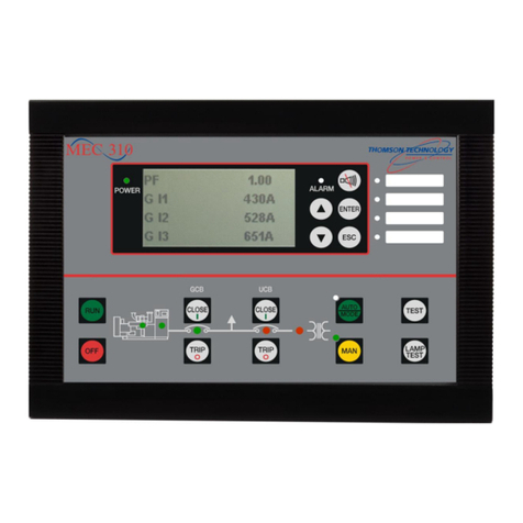
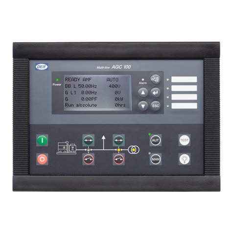
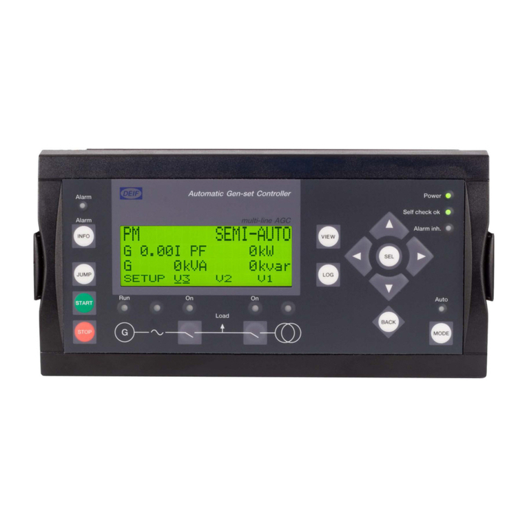
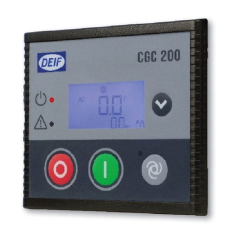
Deif CGC 200 Installation and operation manual

DEIF A/S · Frisenborgvej 33 · DK-7800 Skive · Tel.: +45 9614 9614 · Fax: +45 9614 9615 · info@deif.com · www.deif.com
INSTALLATION AND COMMISSIONING INSTRUCTIONS
Compact Genset Controller, CGC 200
● Mounting
● Terminals and wiring
● Commissioning, using the Utility
Software and/or the front panel
Document no.: 4189340806B
SW version:

1. Introduction
1.1. About the Installation and commissioning instructions...........................................................................3
1.1.1. General purpose ...........................................................................................................................3
1.1.2. Intended users ..............................................................................................................................3
1.1.3. Revision information .....................................................................................................................3
1.1.4. Software version ...........................................................................................................................3
1.1.5. Getting technical support...............................................................................................................3
1.1.6. Other technical documentation......................................................................................................3
1.2. Warnings, safety and legal information..................................................................................................4
1.2.1. Warnings and notes.......................................................................................................................4
1.2.2. Safety issues ................................................................................................................................4
1.2.3. Factory settings ............................................................................................................................5
1.2.4. Electrostatic discharge awareness ...............................................................................................5
1.2.5. Legal information ..........................................................................................................................5
2. Installation
2.1. Tools.......................................................................................................................................................6
2.1.1. Tools required................................................................................................................................6
2.2. Wiring and terminals...............................................................................................................................6
2.2.1. Connection of 1-phase voltage .....................................................................................................6
2.2.2. Wiring diagram...............................................................................................................................7
2.2.3. Digital inputs .................................................................................................................................7
2.2.4. List of terminal connections ..........................................................................................................8
2.2.5. Connecting the terminals...............................................................................................................9
3. Mounting
3.1. CGC 200 mounting...............................................................................................................................10
3.1.1. Mounting of the unit.....................................................................................................................10
3.1.2. Unit dimensions and panel cutout................................................................................................10
3.1.3. Tightening torques.......................................................................................................................10
4. Commissioning
4.1. Overview and parameter list.................................................................................................................11
4.1.1. Sequence.....................................................................................................................................11
4.1.2. People and preparation...............................................................................................................11
4.1.3. Parameter list...............................................................................................................................12
4.2. Wiring...................................................................................................................................................16
4.2.1. Checking the wiring.....................................................................................................................16
4.3. Commissioning using the Utility Software............................................................................................16
4.3.1. Installing the Utility Software .......................................................................................................16
4.3.2. Starting the Utility Software ........................................................................................................19
4.3.3. Utility Software pages and icons..................................................................................................22
4.3.4. Parameters page.........................................................................................................................23
4.3.5. Configuring inputs and outputs....................................................................................................26
4.3.6. Changing parameters..................................................................................................................26
4.3.7. Writing to the controller................................................................................................................27
4.3.8. Other Utility Software pages .......................................................................................................28
4.4. Commissioning using the front panel...................................................................................................28
4.4.1. Changing parameters using the front panel.................................................................................28
5. Glossary
5.1. Abbreviations and terms.......................................................................................................................30
5.1.1. Abbreviations...............................................................................................................................30
5.1.2. Terms...........................................................................................................................................31
5.1.3. Units.............................................................................................................................................32
CGC 200 installation and commissioning
instructions 4189340806 UK
DEIF A/S Page 2 of 32

1. Introduction
1.1 About the Installation and commissioning instructions
1.1.1 General purpose
These are the Installation and commissioning instructions for DEIF’s Compact Genset Controller, CGC
200. The general purpose is to provide information for the correct installation and commissioning of CGC 200.
Read this manual before installing or commissioning the CGC 200. Failure to do this could re-
sult in human injury or damage to the equipment.
1.1.2 Intended users
The instructions are mainly intended for the people responsible for installing and commissioning the genset
control system.
1.1.3 Revision information
The letter at the end of the document number on the front page indicates the revision number of this docu-
ment.
The latest version of this document can be downloaded at www.deif.com. If you click on the revision letter to
the right of the document name, the revision history is displayed.
1.1.4 Software version
This document is based on the following software versions:
Software type Software version
CGC 200 firmware CGC 200 SW version 1.xx
Utility software Multi-line 2 Utility Software v.3.x.
1.1.5 Getting technical support
You can read about service and support options on the DEIF website, www.deif.com. You can also find con-
tact details on the DEIF website.
You have the following options if you need technical support for your controller:
● Technical documentation: All the product technical documentation is available on the DEIF website.
● Training: You can ask for training.
● Support: You can call or email DEIF. DEIF offers 24-hour support. There may also be a local DEIF sub-
sidiary.
● Service: DEIF engineers can help with design, commissioning, operating and optimisation.
1.1.6 Other technical documentation
The CGC 200 documentation consists of the following documents:
● Quick start guide
● Front panel
● Initial start-up
● Parameter setting
● Wiring diagram
CGC 200 installation and commissioning
instructions 4189340806 UK
Introduction
DEIF A/S Page 3 of 32

● Mounting
● Some technical specifications
● Data sheet
● Description, features, functions and approvals
● Layout and dimensions
● Terminals and wiring diagram
● Technical specifications
● Designer's handbook
● Description of functions and sequences
● Parameters
● Utility software
● Installation and commissioning instructions
● Tools required
● Mounting the controller
● Terminals and wiring diagram
● Parameters
● Sequence for commissioning
● Commissioning using the utility software
● Commissioning using the front panel
● Technical support
● Operator's manual
● Basic operator tasks
● Front panel
● Parameters
● Utility software
● Technical support
Glossaries are included in the Designer's handbook, the Installation and commissioning instructions
and the Operator's manual.
1.2 Warnings, safety and legal information
1.2.1 Warnings and notes
A number of warnings and notes are included in this document. These are highlighted, to separate them from
the general text.
Warnings indicate potentially dangerous situations. If the guidelines are not followed, these sit-
uations could result in death, personal injury or damaged equipment.
Notes provide general, helpful information.
1.2.2 Safety issues
Installing and operating the unit may require work with dangerous currents and voltages. The installation must
only be carried out by authorised personnel who understand the risks involved in working with live electrical
equipment.
Hazardous live currents and voltages. Do not touch any terminals, especially the AC measure-
ment inputs. Touching the terminals could lead to injury or death.
CGC 200 installation and commissioning
instructions 4189340806 UK
Introduction
DEIF A/S Page 4 of 32

DEIF does not recommend using the PC USB as the primary power supply for the CGC 200.
The power drawn on start up exceeds the USB standard and may damage the PC.
1.2.3 Factory settings
The controller is delivered pre-programmed from the factory with a set of factory settings. These are based on
average values and are therefore not necessarily correct for your genset. All controller parameters must be
checked before running the genset.
1.2.4 Electrostatic discharge awareness
Protect the controller terminals from static discharge during installation. You must also protect the terminals if
you need to remove the controller.
These precautions are no longer necessary once the controller is correctly installed and connected, as re-
quired by the designer's wiring diagram.
1.2.5 Legal information
DEIF takes no responsibility for the installation or operation of the genset. Contact the genset company if you
have any doubt about installing or operating the genset.
The controller must not be opened by unauthorised personnel. If opened, the warranty is void.
Disclaimer
DEIF A/S reserves the right to change any of the contents of this document without prior notice.
Trademarks
DEIF, power in control and the DEIF logo are trademarks of DEIF A/S.
Windows is a registered trademark of Microsoft Corporation in the United States and other countries.
All trademarks are the properties of their respective owners.
Copyright
© Copyright DEIF A/S 2012. All rights reserved.
CGC 200 installation and commissioning
instructions 4189340806 UK
Introduction
DEIF A/S Page 5 of 32

2. Installation
2.1 Tools
2.1.1 Tools required
The following tools are required to install the controller:
Tool Used to
Conducting wrist strap Prevent electrostatic discharge damage to controller
Flat-bladed screwdriver with 3.2 mm (1/8") tip Tighten the mounting screw clamps (optional).
Tighten terminal block screws.
Do not use power tools to tighten the screws. Too much torque will damage the controller and
the terminal blocks.
2.2 Wiring and terminals
2.2.1 Connection of 1-phase voltage
The drawing below shows the connection of the generator to the controller terminals, for a 1-phase voltage
system. Refer to the wiring diagram for more information.
CGC 200 installation and commissioning
instructions 4189340806 UK
Installation
DEIF A/S Page 6 of 32

2.2.2 Wiring diagram
A wiring diagram for a typical installation is given below. Your system's wiring diagram may be different to the
diagram given below, since a different configuration may have been chosen.
Fuses
Fuses must be used to protect the controller. The auxiliary supply (DC) fuse rating must not be more than 2
A. The Genset L (AC) fuse rating must not be more than 1 A.
Grounding
The ground (Aux. supply -) is common for digital inputs. On the diagram below, the wiring drawn in the con-
troller box is internal wiring (this wiring is part of controller, and therefore not connected externally).
Connect the wiring according to the designer's wiring diagram for your system.
2.2.3 Digital inputs
All digital inputs are 12 or 24 Vdc optocouplers. The typical wiring is illustrated below:
CGC 200 installation and commissioning
instructions 4189340806 UK
Installation
DEIF A/S Page 7 of 32

Common
Switch
0 Vdc
Digital input
The digital inputs require DC voltage. AC voltage will damage the controller.
2.2.4 List of terminal connections
The power supply, inputs and outputs are connected to the CGC 200 terminals. CGC 200 also has a USB B-
socket for connecting to a PC. The terminal connections are listed in the following table.
No. Name Type Details
1 + Power supply + 8 to 35 Vdc
2 - Power supply - Ground
3 MPU Input RPM input Magnetic pickup, or tacho generator
4 Input 1 Digital input Coolant temperature switch, or configura-
ble
5 Input 2 Digital input Low oil pressure switch, or configurable
6 Emergency Stop Input
3
Digital input Emergency stop input (Auxiliary)
7 Input 4 Digital input Remote start, or configurable
8 Input 5 Digital input Configurable
9 Gens L Generator voltage L1 Generator voltage measurement
10 Gens N Generator neutral Generator voltage measurement
11 Fuel Output Relay output (normally open) Run coil
12 Start Output Relay output (normally open) Starter (crank)
13 Config. Output1 Relay output (normally open) Configurable
14 Config. Output2 Relay output (normally open) Configurable
15 Config. Output3 Relay output (normally open) Configurable
USB USB Service Port USB B female connection For connection to a PC
CGC 200 installation and commissioning
instructions 4189340806 UK
Installation
DEIF A/S Page 8 of 32

2.2.5 Connecting the terminals
The wiring is connected to the controller terminals using pull-apart PCB terminal blocks.
For the MPU input, a magnetic head signal input and a shielding line are recommended.
Protect the controller terminals from static discharge during installation.
For safety reasons, the work must be carried out by qualified personnel.
To connect the terminals:
1. Connect each wire to the correct connection on the terminal block, then tighten the screw using a flat-
bladed screwdriver.
2. Make sure that the removable part of the terminal block is pressed all the way into the terminal block on
the CGC 200.
CGC 200 installation and commissioning
instructions 4189340806 UK
Installation
DEIF A/S Page 9 of 32

3. Mounting
3.1 CGC 200 mounting
Protect the controller terminals from static discharge during installation.
3.1.1 Mounting of the unit
The unit is designed for mounting by means of two fixing clamps, which are included at delivery.
3.1.2 Unit dimensions and panel cutout
The unit is designed for mounting in the panel front.
In order to ensure optimum mounting, the panel door must be cut out according to the following measure-
ments:
H × W = 68.00 × 80.00 +0.40 mm and -0.00 mm
H × W = 2.68" × 3.15" + 0.02" and -0.00"
78.50
66.50
94.75
82.75
43.00
8
7
6
5
4
3
2
1
11
12
13
14
15
10
9Gens L
Gens N
Fuel Output
Start Output
Config. Output 1
USB
Config. Output 3
MPU Input
Input 4
Emergency Stop
Input 3
Input 2
Input 1
-
+
Power Supply 8-35 V ,2 A
Relay Outputs 30 V ,1 A D002-1112
Config. Output 2
Input 5
36.00 0.3 Nm
3.1.3 Tightening torques
Unit panel door mounting: 0.3 Nm (see diagram in "Unit dimensions and panel cutout")
Plug connections (terminals): 0.5 Nm
CGC 200 installation and commissioning
instructions 4189340806 UK
Mounting
DEIF A/S Page 10 of 32

4. Commissioning
4.1 Overview and parameter list
4.1.1 Sequence
The sequence followed to commission the CGC 200 can be varied according to your needs.
For example, you can upload the parameters from the utility software before mounting and wiring up the con-
troller. This can be done in an office environment, and may simplify commissioning.
Alternatively, you can upload the parameters to the controller where it is mounted, using a laptop computer.
You can then use the utility software on the laptop computer to adjust the parameters as required, as well as
to check the wiring.
Finally, you can use the CGC 200 front panel to adjust the parameters during commissioning.
4.1.2 People and preparation
Commissioning requires in-depth knowledge of the genset, the system and the controller. The people respon-
sible for commissioning must therefore be suitably qualified.
In addition, the people responsible for commissioning must have the following information from the system
designer:
● Detailed system drawing
● Wiring diagram for the controller
● Configuration of the inputs and outputs
● Controller parameter settings
CGC 200 installation and commissioning
instructions 4189340806 UK
Commissioning
DEIF A/S Page 11 of 32

4.1.3 Parameter list
The parameters used by CGC 200 that can be changed from the controller front panel are listed in the table
below.
Param-
eter
num-
ber
Parameter
name
Range De-
fault
value
Value
chos-
en*
Description
P00 Auto start delay 0 to 3600 s 1 Timer for starting using the Auto start
signal
P01 Auto stop delay 0 to 3600 s 1 Timer for stopping after the Auto start
signal is removed
P02 Start attempts 1 to 10 3 Number of start attempts in one start se-
quence
P03 Start prepare 0 to 300 s 0 Timer for start prepare
P04 Start on time 3 to 60 s 8 Timer for starter ON time during crank-
ing
P05 Start off time 3 to 60 s 10 Timer for starter OFF time before a new
start attempt is made
P06 Initial inhibit de-
lay
1 to 60 s 10 Timer for bypassing frequency and volt-
age shutdown during starting
P07 Idle start 0 to 3600 s 0 Timer for idle speed after starting
P08 GB close delay 3 to 3600 s 10 Timer for generator breaker close after
frequency and voltage OK
P09 Cooldown time 3 to 3600 s 10 Cooling down time
P10 Idle stop 0 to 3600 s 0 Timer for idle speed before stopping
P11 Extended stop 0 to 120 s 20 Timer for extended stop
P12 Stop failure 0 to 120 s 0 Maximum allowable time for stopping
the genset
P13 Number of teeth 10 to 300 118 The number of teeth on flywheel. This is
only used when MPU is selected as run-
ning detection (see P40).
P14 Number of gen.
poles
2 to 32 4 The number of genset poles. This is
used in the frequency calculation.
P15 Hz/V OK delay 0 to 20.0 s 10.0 Voltage and frequency OK delay after
starting of genset
P16 G U > 30 to 360 V 264 Generator over-voltage protection
P17 G U < 30 to 360 V 196 Generator under-voltage protection
P18 G RPM < 0 to 6000
RPM
1200 Generator under-speed protection, if
running detection (see P40) is RPM in-
put only
CGC 200 installation and commissioning
instructions 4189340806 UK
Commissioning
DEIF A/S Page 12 of 32

Param-
eter
num-
ber
Parameter
name
Range De-
fault
value
Value
chos-
en*
Description
P19 G RPM > 0 to 6000
RPM
1710 Generator over-speed protection, if run-
ning detection (see P40) is RPM input
only
P20 G f < 0 to 75.0 Hz 45.0 Generator under-frequency protection
P21 G f > 0 to 75.0 Hz 57.0 Generator over-frequency protection
P22 Running feed-
back timer
0 to 20.0 s 5.0 Maximum allowable time for running de-
tection (see P40)
P23 U > aux. term.1 12.0 to 40.0 V 33.0 High battery supply voltage
P24 U < aux. term.1 4.0 to 30.0 V 8.0 Low battery supply voltage
P25 Relay 01 0 to 6 4 See Table 1: Configurable output func-
tions
P26 Relay 02 0 to 6 1
P27 Relay 03 0 to 6 2
P28 Digital input 1 0 to 10 5 See Table 2: Configurable input func-
tions
P29 Digital input 1
timer
0 to 20.0 s 10.0
P30 Digital input 2 0 to 10 6
P31 Digital input 2
timer
0 to 20.0 s 2.0
P32 Digital input 3 0 to 10 4
P33 Digital input 3
timer
0 to 20.0 s 1.0
P34 Digital input 4 0 to 10 2
P35 Digital input 4
timer
0 to 20.0 s 3.0
P36 Digital input 5 0 to 10 1
P37 Digital input 5
timer
0 to 20.0 s 10.0
P38 Default genset
mode
0 to 2 0 0: Stop mode
1: Manual start
2: Auto start
P39 Display pass-
word
0 to 9999 2000 Prevents unauthorised changes to pa-
rameters using the controller front panel
CGC 200 installation and commissioning
instructions 4189340806 UK
Commissioning
DEIF A/S Page 13 of 32
Param-
eter
num-
ber
Parameter
name
Range De-
fault
value
Value
chos-
en*
Description
P40 Running detect. 0 to 2 2 0: RPM
1: Genset frequency
2: RPM and frequency (running detec-
tion is present when the value required
to remove the starter is met for either
engine speed (see P41) or genset fre-
quency (see P42))
For RPM, P13 and P41 must be de-
fined.
For frequency, P42 must be defined.
P41 Remove starter
RPM
0 to 3000
RPM
360 Minimum engine speed required for re-
moval of the starter and running detec-
tion
P42 Remove starter
Hz
10.0 to 30.0
Hz
14.0 Minimum genset frequency required for
removal of the starter and running de-
tection
*You can fill in the values chosen for your system.
CGC 200 installation and commissioning
instructions 4189340806 UK
Commissioning
DEIF A/S Page 14 of 32
The parameters used by CGC 200 that can only be viewed and changed from the utility software are listed in
the table below.
Param-
eter
number
Parameter name Range De-
fault
value
Value
chos-
en*
Description
43 Calibrate AC voltage 700 to 1300 1000 See the Designer's handbook
for more information
44 Calibrate battery voltage 700 to 1300 1000 See the Designer's handbook
for more information
45 Running hours offset
(9999-19998)
0 to 9999
hours
0 Additional offset for the genset's
running time timer
46 Running hours offset
(0-9999)
0 to 9999
hours
0 Additional offset for the genset's
running time timer
47 Running minutes offset 0 to 59 mi-
nutes
0 Additional offset for the genset's
running time timer
48 Running seconds offset 0 to 59 s 0 Additional offset for the genset's
running time timer
49 Start attempts offset
(9999-19998)
0 to 9999 0 Additional offset for the genset's
start attempts counter
50 Start attempts offset
(0-9999)
0 to 9999 0 Additional offset for the genset's
start attempts counter
*You can fill in the values chosen for your system.
Table 1: Configurable output functions
Configurable output function Value in the controller Config. output*
Not used 0
Common alarm 1
Stop coil 2
Pre-heat 4
Idle speed 3
Close breaker 6
*You can fill in the number of the corresponding relay configured for this function in your system.
CGC 200 installation and commissioning
instructions 4189340806 UK
Commissioning
DEIF A/S Page 15 of 32
Table 2: Configurable input functions
Configurable input function Value in the controller Digital input*
Not used 0
Remote start/stop 6
Low fuel level warning 5
Low oil pressure warning 8
Low oil pressure shutdown 2
High oil temperature warning 7
High oil temperature shutdown 1
High coolant temperature shutdown 9
Auxiliary alarm shutdown (Emergency stop) 4
*You can fill in the number of the corresponding digital input configured for this function in your system.
4.2 Wiring
4.2.1 Checking the wiring
You can use the utility software during commissioning to check the wiring. You can connect the CGC 200 to a
PC using a USB cable and check whether the operating values are as expected. You can use P43 and P44
to calibrate the genset and battery voltage measurements. See the Designer's handbook for more informa-
tion. Voltage calibration is only available through the utility software.
You can also use the CGC 200 front panel to monitor operating values during commissioning.
4.3 Commissioning using the Utility Software
4.3.1 Installing the Utility Software
The Utility Software (USW) must be installed on a PC (either a laptop or a desktop computer) running the
Microsoft Windows operating system.
Do not connect the controller to the PC (using the USB cable) before the software is installed.
Microsoft Windows creates an incorrect USB driver if the controller is connected before the
software is installed. If you have this problem, you need to find the correct USB driver in the
software installation folder and install it.
The USW is normally downloaded from DEIF via the internet.
To download the Utility Software:
1. Open www.deif.com in a browser.
2. Click Documentation and Software in the top menu.
CGC 200 installation and commissioning
instructions 4189340806 UK
Commissioning
DEIF A/S Page 16 of 32
3. Click Software download on the left side of the page.
CGC 200 installation and commissioning
instructions 4189340806 UK
Commissioning
DEIF A/S Page 17 of 32
4. Select Multi-line 2 Utility Software v.3.x. from the drop-down list.
A dialogue box opens, with information about the most recent version of the software.
CGC 200 installation and commissioning
instructions 4189340806 UK
Commissioning
DEIF A/S Page 18 of 32

5. Enter your email address. Click Submit. An email with a link to download the software will be sent to you.
6. Click the link in the email to download the executable Utility Software setup file.
To install the Utility Software:
1. After downloading the software, choose Run. An installation wizard opens.
2. Use the suggested default settings.
● Note: Option N refers to a TCP/IP connection, and is not relevant for CGC 200.
3. When the installation is complete, there will be a Utility Software shortcut icon ( ) on your PC
desktop.
4.3.2 Starting the Utility Software
To start using the Utility Software:
CGC 200 installation and commissioning
instructions 4189340806 UK
Commissioning
DEIF A/S Page 19 of 32

1. Double click the Utility Software shortcut icon ( ) on your desktop. The Utility Software program
will open.
2. The first time you use the Utility Software, you need to set up the connection to the CGC 200:
DEIF does not recommend using the PC USB as the primary power supply for the CGC
200. The power drawn on start up exceeds the USB standard and may damage the PC.
1. Use the USB cable to connect the CGC 200 to the PC. The CGC 200 Power OK LED should light up.
2. If the Settings dialogue box does not open automatically, select File, then click Settings. Alternative-
ly, press F3, or click the Settings icon ( ) on the toolbar.
3. Under Communication, in the Communication type field, select Service port. The other communica-
tion types are not relevant for CGC 200.
4. In the Communication port drop-down list, select the port that indicates that the CGC 200 is present,
as indicated above. If no ports indicate the CGC 200, check the connection and click Scan ports.
5. Click OK.
3. If you already have a connection set up, select Connection from the menu, then click Connect. Alterna-
tively, press F5.
After successful connection, a Device page opens (see example below). The Device page shows the current
status of the device, the type of device, the connection status, the device software version, and so on.
CGC 200 installation and commissioning
instructions 4189340806 UK
Commissioning
DEIF A/S Page 20 of 32
Other manuals for CGC 200
1
Table of contents
Other Deif Controllers manuals

Deif
Deif AGC-4 Mk II User manual

Deif
Deif GC-1F User manual

Deif
Deif GPC-3 Hydro User manual

Deif
Deif AGC 200 User manual

Deif
Deif iE 250 User manual

Deif
Deif SGC 420 Mk II User manual

Deif
Deif AGC-4 Mk II User manual

Deif
Deif AGC 200 Series Instruction Manual

Deif
Deif AGC-4 Mk II User manual

Deif
Deif CGC 400 User manual