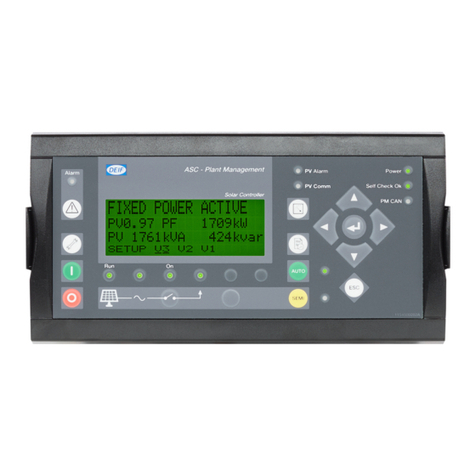
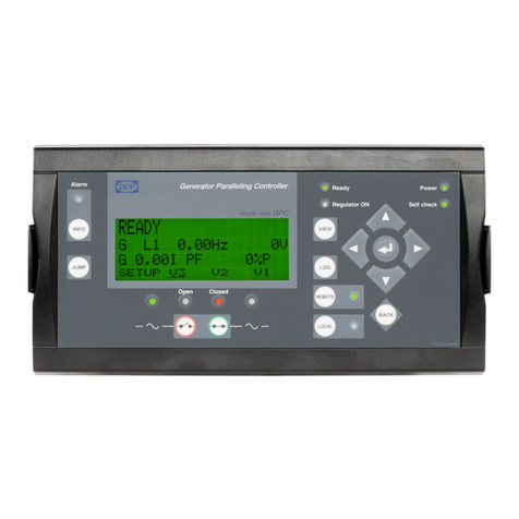
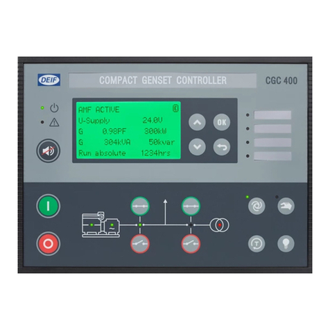
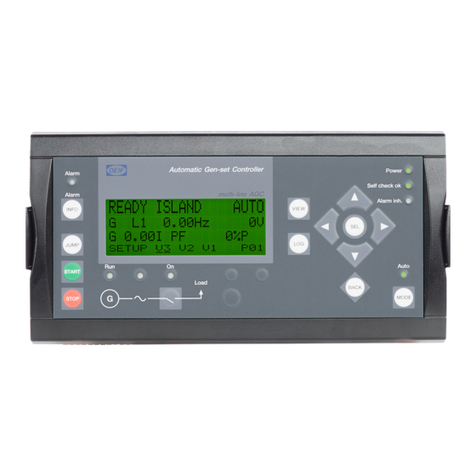
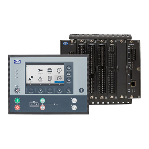
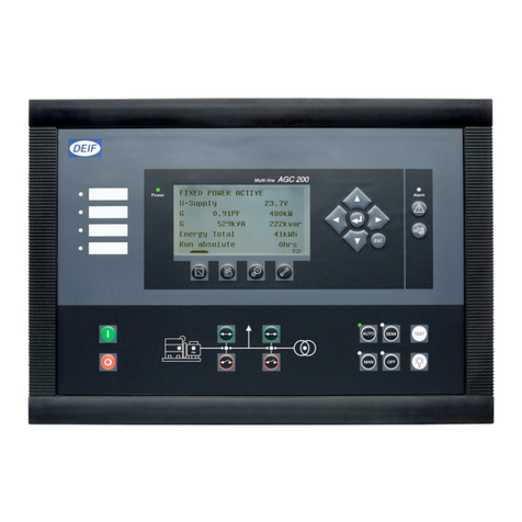
Deif MPC-1 Owner's manual

DEIF A/
S
DEIF A/S Tel: (+45) 9614 9614
Frisenborgvej 33, DK-7800 Skive Fax: (+45) 9752 4720
Denmark E-mail: deif@deif.com
Programming manual
Multi power controller MPC-1
multi-line
4189340103E
·Complete control system in one package
- Island operation
- Parallel with mains operation
- Emergency generator control
·3-phase AC measurements
·Calculation of complex AC values
·Generator and mains supervision and protection
·Prime mover start/supervision/stop
·Breaker synchronisation

List of contents
1. Warnings, legal information and notes to CE-marking ............................... 4
2. Parameter setting ........................................................................................... 4
2.1 Select parameter menu .................................................................................... 4
2.1.1 ”P” pushbutton .................................................................................................. 4
2.1.2 ”5” pushbutton ................................................................................................. 5
2.1.3 ”4” pushbutton ................................................................................................. 5
2.2 Software version ............................................................................................... 5
2.3 Code number .................................................................................................... 5
2.4 Service display.................................................................................................. 6
2.5 Mains power setpoints ...................................................................................... 6
2.6 Base settings .................................................................................................... 7
2.6.1 Generator no. (only important with Option E) ................................................... 8
2.6.2 Generator frequency......................................................................................... 8
2.6.3 Nominal frequency............................................................................................ 8
2.6.4 Generator voltage ............................................................................................. 8
2.6.5 Current transformers and nominal power ......................................................... 9
2.7 Controller settings............................................................................................. 9
2.7.1 Frequency control relay outputs (standard) ...................................................... 9
2.7.2 Frequency controller analog output (Option B1/B3) ....................................... 10
2.7.3 Voltage controller relay outputs (standard)..................................................... 10
2.7.4 Voltage controller analog output (Option B2/B3) ............................................ 11
2.7.5 Constant power controller and external setpoint............................................. 11
2.7.6 Active power load sharing............................................................................... 13
2.7.7 Reactive power load sharing .......................................................................... 13
2.7.8 Breaker configuration...................................................................................... 14
2.7.9 Emergency power........................................................................................... 15
2.7.10Power factor controller.................................................................................... 16
3. Generator and engine protection parameter menu ................................... 16
3.1 Generator reverse power/overload protection ................................................ 17
3.2 Asymmetric load monitoring ........................................................................... 17
3.3 Generator frequency monitoring ..................................................................... 18
3.4 Generator overcurrent protection.................................................................... 18
3.5 Generator 3-phase voltage monitoring ........................................................... 19
3.6 Mains frequency supervision .......................................................................... 19
3.7 Mains 3-phase voltage supervision ................................................................ 20
3.8 Vector jumping monitoring.............................................................................. 20
3.9 Battery voltage................................................................................................ 21
4. Aux inputs parameter menu ........................................................................ 21
4.1 Relay manager ............................................................................................... 21
4.2 Digital input..................................................................................................... 23
4.3 Analog input.................................................................................................... 25
4.4 Temperature inputs......................................................................................... 27
4.5 Analog output manager (not available if Option E is chosen)......................... 28
5. Digital inputs, texts....................................................................................... 30

Programming manual MPC-1
4189340103E
6. Start/stop sequences parameter menu....................................................... 31
6.1 Option E and F: Load sharing......................................................................... 31
6.2 Dielsel/gas engine selection ........................................................................... 33
6.3 Start sequence, diesel engine ........................................................................ 33
6.4 Start sequence, gas engine ............................................................................ 33
6.5 Common start/stop sequence, diesel or gas engine....................................... 34
6.6 Counter settings.............................................................................................. 35
This manual relates to software version 1.0x (versions 1.01…1.09)
For further information, see ”User’s manual, multi power” and ”Installation manual,
multi power controller MPC-1, ref. No. 4189340102”.

1. Warnings, legal information and notes to CE-marking
This manual gives general guidelines on how to install and operate a gen-set using
the product MPC-1. Installing and operating a gen-set implies generation of
dangerous current and voltages, and therefore this should be done by qualified
personnel only. DEIF takes no responsibility for operation or installation of gen-sets or
other systems using the described methods in this manual. If there is any doubt about
how to install or operate the gen-set the company responsible for installation or
operation must be contacted.
MPC-1 is CE-marked with respect to the EMC directive for residential, commercial and
light industry plus industrial environment.
MPC-1 is CE-marked with respect to the low-voltage directive for 300 V class
systems, protection class III and pollution degree 2.
Take precautions against electrostatic discharges when service or installation
operations are done. The unit is protected against electrostatic discharge in normal
operating situations, but service or installation operations can cause unforeseen
electrostatic discharges.
2. Parameter setting
In the following, use the blank column "commissioning value" to write down your own
settings.
2.1 Select parameter menu
By pushing the buttons "V" and "SET" simultaneously a swap between mode "auto"
and "parameter" can be carried out. The functions of the buttons "LOG", "V" and
"SET" are changed to the indications below the buttons, i.e. "LOG" turns to "P", "V"
turns to "5" and "SET" turns to "8". The "auto" LED will flash.
In parameter mode, all set-points and timers can be changed.
If no parameter setting inputs has taken place for 30 secs, the MPC-1 will return to
"auto" mode.
To make key-in of values easier, the function is equipped with a "sweep" function. By
holding a button down, a fast sweep through values can be carried out.
The first thing shown is the software version. To continue, press "P".
2.1.1 ”P” pushbutton
Stores the keyed in display parameter value, jump to the next parameter.

Programming manual MPC-1
4189340103E
If the display value has been changed via the "5" or "8" buttons, the new value can
be stored by pushing the "P" button once. If the button is pushed twice, the display will
jump to the next parameter.
2.1.2 ”5” pushbutton
Steps the chosen displayed value up one unit (within allowed limits). Digit is chosen
by moving the cursor.
2.1.3 ”4” pushbutton
Analog values: Moves the cursor to the next digit
Binary values: Swap of different functions (e.g.: ON/OFF)
2.2 Software version
DISPLAY Factory
set
Commis-
sioning
value
DESCRIPTION
Software version
V 1.01
The software version is factory set.
Check that it matches the version
indicated in the manuals.
2.3 Code number
DISPLAY Factory
set
Commis-
sioning
value
DESCRIPTION
Enter code
Number xxxx
random
and
level
The display will show a random no.
The random no. is used at a later
stage if the chosen passwords have
been lost. Call factory for help on the
code to be used.
NOTE: If you change this no., one of
the 2 code level codes must be used
(see later). It is therefore
recommended, that you leave the no.
during programming/commisioning.

2.4 Service display
DISPLAY Factory
set
Commis-
sioning
value
DESCRIPTION
Service display ON ON OFF/ON. Selection of display of
double voltage, frequency and
phase angle and relay positions
(commissioning help).
If ON, the next 3 displays will follow:
Bus:000V 00,00Hz
Gen:000V 00,00Hz
Busbar voltage, Busbar frequency
Generator voltage, generator
frequency
Main:000V 00,00Hz
Bus:000V 00,00Hz
Mains voltage, mains frequency
Busbar voltage, busbar frequency
Relay: MCB OFF
f U GCB OFF
Breaker status:
Mains breaker ON/OFF
Gen. Breaker ON/OFF
Control relays:
Freq. UP: f+
Freq. DOWN: f-
Voltage UP: U+
Voltage DOWN: U-
While looking at the service display, the frequency indicator (LED horizontal row
below the display) will act as a LED synchronoscope, with the sync. point at the
centre.
2.5 Mains power setpoints
DISPLAY Factory
set
Commis-
sioning
value
DESCRIPTION
Configurate controls
YES/NO
NO Selection of changing power
setpoints. If NO the following sub-
parameters will not be displayed.

Programming manual MPC-1
4189340103E
Power controller
Pset1 = F0100kW
Setpoint 1 (kW) for constant
power transfer to/from mains(B
indicates "Consumption from ma-
ins", L indicates "Delivery to main-
s", F indicates fixed generator
power). Active setpoint, when
"auto 1" (terminal 3) is connected
to + 24 VDC.
Power controller
Psetp.2 = F0200kW
Setpoint 2 (kW) for constant
power transfer to/from mains.
Active setpoint, when "auto 2" (ter-
minal 5) is connected to + 24
VDC. NOTE: If "Setpoint extern" =
ON (see paragraph 1.8.4), the set-
point 2 input controls the "auto"
function only. The actual setpoint
is determined via a 4(0)...20 mA
transmitter.
NOTE: The F, B or L choice must
be equal to the F, B or L setting of
the analog input zeropoint and
fullscale.
If password protection is active, the following requires the ”level 2” password:
2.6 Base settings
DISPLAY Factory
set
Commis-
sioning
value
DESCRIPTION
Configurate
Base ? YES/NO
NO Selection of changing base values.
If NO the following sub-parameters
will not be displayed.

2.6.1 Generator no. (only important with Option E)
DISPLAY Factory
set
Commis-
sioning
value
DESCRIPTION
Generator no.
01
01 Generator no. 1-8. Selection of
generator no. if more generators are
to be controlled by the power mana-
gement option E.
2.6.2 Generator frequency
DISPLAY Factory
set
Commis-
sioning
value
DESCRIPTION
Generator freq.
f set. = 50.0 Hz
50.0
Hz
Generator frequency setpoint in
island or idle operation 48...62Hz.
2.6.3 Nominal frequency
DISPLAY Factory
set
Commis-
sioning
value
DESCRIPTION
Nominal freq.
Generator
50.0Hz
50.0
Hz
Generator nominal frequency,
parallel running operation 48...62
Hz.
2.6.4 Generator voltage
DISPLAY Factory
set
Commis-
sioning
value
DESCRIPTION
Generator volt.
U set. = 400 V
400V Generator nominal voltage in island
or idle operation 350...440 V.
Volt.transformer
Prim. 10.0kV
10.0
kV
0.5...70 kV. Setting of voltage trans-
former primary value (voltage
transformer version only)
Volt.transformer
Sec. 100V
100V 100/110V. Setting of voltage trans-
former secondary value (voltage
transformer version only)

Programming manual MPC-1
4189340103E
2.6.5 Current transformers and nominal power
DISPLAY Factory
set
Commis-
sioning
value
DESCRIPTION
Current transf.
Generator 0500/5
0500
/5
.../5 or .../1 A. Generator current tran-
sformer primary/secondary nominal
current. The size of current transfor-
mer must be selected in such a man-
ner, that there, by full generator load,
runs min. 40% of nominal current on
transformer secondary side. If not,
non-correct functions may appear.
Power measuring
Gen. Threephase
3-pha-
se
1-phase/3-phase. "1-phase": single
phase (phase L1) current used for
power and power factor calculation.
"3-phase": 3-phase current measure-
ment is used for calculation.
Nominal power
Gen. = 0200 kW
0200
kW
5...6900 kW. Nominal power for the
generator in question. Max. power
limt for the power regulators.
Nominal current
Gen. = 0300 A
0300A 0...3000 A. Generator nominal
current. Max. current limit for the
power regulators.
Current trafo
mains 1000/5
.../5 or .../1 A. Single phase mains
current is used for options A and F.
The size of current transformer must
be selected in such a manner, that
there, by full generator load, runs
min. 40% of nominal current on
transformer secondary side. If not,
non-correct functions may appear.
Define level 1
Code 0001
0001 User definable password for level 1
(user) access
Define level 2
Code 0002
0002 User definable password for level 2
(programmer) access
2.7 Controller settings
2.7.1 Frequency control relay outputs (standard)
DISPLAY Factory
set
Commis-
sioning
value
DESCRIPTION

Freq. Controller
ON
ON Frequency controller ON/OFF.
"cursor " selects ON/OFF value.
"select" enters the chosen value.
Freq.controller
Ramp 05Hz/s
05
Hz/s
2...50 Hz/s. Frequency ramp
speed
Freq. Controller
Nz = 0.10 Hz
0.05
Hz
0.05...1.00 Hz neutral zone.
Island operation: Frequency within
f nom. ± neutral zone causes no
controller action.
Dynamic synchronisation: Max. dif-
ferential frequency = neutral zone
value.
Freq. Controller
Time pulse>080ms
065
ms
10...250 ms. Min. impulse time for
controller relay outputs.
Min. Time required for the engine
governor to react on impulse.
Freq. Controller
Gain.Kp = 15.0
15.0 1.0...99.9 amplification factor for
frequency controller.
The Kp affects the ON time for the
relay output. Kp = ON time .
2.7.2 Frequency controller analog output (Option B1/B3)
DISPLAY Factory
set
Commis-
sioning
value
DESCRIPTION
Base pos. freq.
10%
10% 0...50 %. Idle run genset frequency
at startup. Relates to system base
frequency.
P-amplification
f Kpr 100
100 0...500. P-band factor for controller
function
Delay time
f Tn 02.5s
02.5s 0...99s. I-time factor for controller
2.7.3 Voltage controller relay outputs (standard)
DISPLAY Factory
set
Commis-
sioning
value
DESCRIPTION
Volt. controller
ON
ON Voltage controller ON/OFF.
"cursor " selects ON/OFF value.
"select" enters the chosen value.

Programming manual MPC-1
4189340103E
Volt. controller
Nz = 20 V
01.0V 4...60 V (1...20 V) neutral zone.
(../110(100) V version: The voltage
refers to secondary side of voltage
transformer).
Island operation: Voltage within U
nom. ± neutral zone causes no
controller action.
Dynamic synchronisation: Max.
Differential voltage = neutral zone
value.
Volt. controller
Time pulse>080ms
065ms 10...250 ms. Min. Impulse time for
controller relay outputs.
Min. time required for the ge-
nerator AVR to react on impulse.
Volt. controller
Gain Kp = 10.0
15.0 1.0...99.9 amplification factor for
frequency controller.
The Kp affects the ON time for the
relay output. Kp = ON time .
2.7.4 Voltage controller analog output (Option B2/B3)
DISPLAY Factory
set
Commis-
sioning
value
DESCRIPTION
P-amplification
V Kpr 100
100 0...500. P-band factor for controller
function
Delay time
V Tn 02.5s
02.5s 0...99s. I-time factor for controller
2.7.5 Constant power controller and external setpoint
DISPLAY Factory
set
Commis-
sioning
value
DESCRIPTION
Power controller
ON
ON/OFF. ON: In parallel with
mains, the generator will maintain
a constant power production.
Power controller
Ramp=010kW/s
010 kW/s 5...100 kW/s. Ramp speed for
power controller.
Power limit
Pmax.= 120 %
100% 10...120%. Power controller upper
limit value, referring to generator
nominal power. Upper limit, to pre-
vent overload, e.g when running
constant power from mains (peak
shaving, option F).

Power limit
Pmin. = 0...50 %
00% 0...50%. Power controller lower
limit value, referring to generator
nominal power. Lower limit, to
prevent low load running when
running constant power from
mains (peak shaving, option F).
Power set point
External OFF
OFF ON/OFF. Selection of external set
point via analog input no. 1
(terminal 93-94).
If power set point
external = ON, the
following displays
will occur:
Analog input
0.20mA
0-20mA 0/4-20 mA input type celection
Ext setpoint
0(4)mA =F0000kW
Zeropoint and fullscale for
External setpoint.
F = Fixed generator load
B = Power import from mains
(option F only)
L = Power export to mains (option
F only)
Ext. Setpoint
20 mA = F0200kW
RS232 control
OFF
OFF ON/OFF. Selection of command
and setpoint settings via RS232
interface (Option D only)
Power controller
Nz = 05.5%
02.5% 0.5...25.5%. Neutral zone, active
power controller, percentage of
generator nominal power. In paral-
lel with mains, the active power
will be within Pset ±Nz.
Power contr.
Gain Kp = 10.0
05.0 1.0...99.9. Amplification factor,
active power controller. The Kp af-
fects the ON time for the relay out-
put. Kp = ON time .
Power contr.
Sens.red. * 2.0
*2.0 1.0...99.9. After reach of setpoint,
there will be a delay of min. 5 s
before any command pulse is set
i.e. the sensitivity is reduced.
Example: With a Nz of 2.5% and
Sens.red of 2.0, the Nz will, for 5
s, be raised to 5%. After this, if ac-
tual value is within 5%, Nz returns
to 2.5%. This prevents hunting of
the controller.

Programming manual MPC-1
4189340103E
Part load start
setp. = 015%
0...100%. If the generator needs
warming-up before taking load
after synchronisation, this setpoint
can be used.
Part load start
time 005s
0...600s. Running time for
warming-up
2.7.6 Active power load sharing
DISPLAY Factory
set
Commis-
sioning
value
DESCRIPTION
Active power
Load-share ON
ON ON/OFF. If a parallel run with other
generators is to take place, this va-
lue must be ON. Otherwise, the gen-
set will not take part of the load
sharing
Loadsharing
Factor 50%
50% 0...100%. The load sharing factor
determines the stability of the main
control parameter (in island
operation: Frequency, in parallel
with mains: Power transport value).
Higher value =more stable primary
parameter value, less stable genera-
tor active load (load sharing stability)
and vice versa.
2.7.7 Reactive power load sharing
DISPLAY Factory
set
Commis-
sioning
value
DESCRIPTION
Reactive power
Load-share ON
ON ON/OFF. If a parallel run with other
generators is to take place, and
reactive power loadsharing is to
take place, this value must be ON.
Otherwise, the genset will not take
part of the reactive power load
sharing

Loadsharing
Factor 50%
50% 0...100%. The load sharing factor
determines the stability of the main
control parameter (in island
operation: Voltage, in parallel with
mains: Reactive Power transport
value). Higher value =more stable
primary parameter value, less sta-
ble generator reactive load (load
sharing stability) and vice versa.
2.7.8 Breaker configuration
DISPLAY Factory
set
Commis-
sioning
value
DESCRIPTION
Configurate
Breaker? YES
YES YES/NO. If NO is chosen, the
following sub-menus will not be
shown.
Synchronize
functions ON
ON ON/OFF. If off is chosen,
synchronisation will not take
place.
Synchronize
df max. = 0.18 Hz
0.18Hz 0.05...0.45 Hz (positive slope).
Generator frequency must be
busbar frequency + 0...df max. to
obtain dynamic synchronisation.
Synchronize
df min. = -0.10 Hz
-0.10Hz 0.00...-0.30 Hz (negative slope).
Generator frequency must be
busbar frequency -0...df min. to
obtain dynamic synchronisation.
Used at return sync to mains af
Synchronize
dU max. = 20 V
16V 4...60 V. Max. Allowable dif-
ferential voltage by closing of
breaker. ../100 or ../110 V voltage
transformer versions: The value
refers to voltage transformer
secondary side.
Synchronize
time pulse>200 ms
200ms 050...250 ms Min. Time duration
of breaker close command relay
output.
Gen. Breaker
Closing t.=050 ms
40...250 ms. Generator breaker
time.
Gen. Breaker
Constant ON
OFF ON/OFF. ON: breaker close
signal in constant when ON.
OFF: Generator breaker close
signal is a pulse.
Mains breaker
Closing t.=050 ms
080ms 40...250 ms. Mains breaker
(option A) time.

Programming manual MPC-1
4189340103E
G.break.blackout
Operation ON
ON ON/OFF. Selects generator
breaker blackout start active
when ON
G.break.blackout
df max.= 0.25Hz
0.25hz 0.05...0.49Hz Blackout start
frequency deviation.
G.break.blackout
dU max. = 40V
40V 2...60 V. Blackout start
undervoltage
m.break.blackout
operation ON
ON ON/OFF. Blackout start, mains
breaker (option A).
Sync. Time contr.
ON
ON ON/OFF. Supervision of syn-
chronisation time of breakers
Mains trip
via GCB
GCB GCB/MCB. Choice of trip of gen.
breaker (GCB) or mains breaker
(MCB) if a mains failure occurs.
Sync time contr.
ON
ON ON/OFF. Choise of
synchronisation time supervision
Sync. Time contr.
Delay time 180s
120s 0...999s. Set-point of synchroni-
sation timer. At runout, alarm
"Sync. Time" and horn output is
released.
2.7.9 Emergency power
DISPLAY Factory
set
Commis-
sioning va-
lue
DESCRIPTION
Config. emer.
Power? YES
YES YES/NO. If NO is chosen, the
following sub-menus will not be
shown.
Emer.power
ON
ON ON/OFF. ON: Upon mains fail, the
genset is started and used as
emergency power source.
Emergency power
start delay 15s
03s 0...99s. Start delay after mains
failure occurs.
Main
Delay time 15s
03s 0...99s. Delay after mains
restoration before re-
synchronising.
Emergency power
stop delay 10s
20s 0...99s. Stop delay after mains
restored. Emergency power supply
running time after return of the
mains.

2.7.10 Power factor controller
DISPLAY Factory set Commis-
sioning
value
DESCRIPTION
Power-factor-
Controller ON
ON/OFF. ON: Running parallel with
mains, the power factor will be kept
at preset value, regardless of
power consumption. By very low
loads (secondary current <5% In),
the control can become unstable.
Therefore, in this case, the control-
ler is overruled.
Pow.fact. contr.
Setpoint.= i 0.95
1...i 0.70 (i = inductive) The reac-
tive power is controlled in such a
manner, that the preset power
factor value is kept constant.
Pow.fact.contr.
Nz = 10.0%
0.5...25.5%. Neutral zone, power
factor controller, percentage of ge-
nerator nominal power. The MGC-1
calculates the reactive power value
necessary to reach the desired
power factor. In parallel with mains,
the reactive power will be within
(Pnom. ±Nz)*cos .
Pow.fact.contr.
Gain. Kp = 10.0
1.0...99.9. Amplification factor,
power factor controller. The Kp af-
fects the ON time for the relay out-
put. Kp = ON time .
3. Generator and engine protection parameter menu
The protective functions are divided into 4 failure modes:
F0: Warning. Gives warning only, no interference with the present running situation.
F1: As F0, but with setting of alarm output : Common failure.
F2: Stop. Trips breaker and stops genset after cooling down time.
F3: Shutdown. Trips breaker and stops genset immediately.
By activation of "shutdown inhibit mode" (terminal 6), functions F2 and
F3 are changed to F1 (shutdown blocking)!!!

Programming manual MPC-1
4189340103E
3.1 Generator reverse power/overload protection
SETTING DIS-
PLAY
Fac-
o
ry set
Commi
s-
sioning
value
ALARM
MESSA-
GE
DESCRIPTION
Config
Alarms?
YES
YES YES/NO. If NO is chosen, the fol-
lowing sub-menus will not be
shown.
Reverse
power/
overld. mon.
ON
ON ON/OFF. Set supervision of
reverse power and overload ON
or OFF.
Reverse po-
wer/
Min. Power=-
10%
-
10%
-99...0...+99%. Reverse/under-
load setpoint referring to genera-
tor nominal power.
Reverse power
delay= 3.0 s
5.0s F2:
Reverse
power
0...9.9 s. Reverse power trip de-
lay. After timer runout, the GCB is
tripped and genset is stopped
after cooling down period.
Gen.- overload
Setpoint
=110%
120
%
80...120 %. Overload setpoint
referring to generator nominal po-
wer.
Gen.-overload
delay = 20s
15s F2: Over-
load
0...99 s. Overload trip delay. After
timer runout, the GCB is tripped
and genset is stopped after
cooling down period.
3.2 Asymmetric load monitoring
SETTING DIS-
PLAY
Fac-
tory
set
Commis-
sioning
value
ALARM
MESSA-
GE
DESCRIPTION
Asymmetric
load
Monitoring
ON
ON ON/OFF. Set supervision of
asymmetric load ON or OFF.
Asymmetric
load
Max.
=050%
050
%
0...100%. Setpoint for asymmetric
load trip.
Asymmetric
load
Delay= 3.0 s
1.0s F2:
Asymm
load
0...9.9 s. Trip delay. After timer
runout, the GCB is tripped and
genset is stopped after cooling
down period.

3.3 Generator frequency monitoring
SETTING DIS-
PLAY
Facto-
ry
set
Commis-
sioning
value
ALARM
MES-
SAGE
DESCRIPTION
Gen.
Frequency
Monitoring
ON
ON ON/OFF. Select generator
frequency supervision ON/OFF.
Gen. Overfreq.
f > 53.0 Hz
55.-
0Hz
F3:
Over-
speed
40...70Hz. Overfrequency set-
point.
Overfreq.
Delay= 2.0 s
0.30s 0...9.9 s. Over frequency trip de-
lay. After timer runout, the GCB is
tripped and genset is stopped im-
mediately.
Gen.
Underfreq.
f < 45.0 Hz
45.0H
z
F3:
Under-
speed
40...70Hz.Underfrequency set-
point.
Underfreq.
Delay = 3.0s
0.50s 0...9.9 s. Underfrequency trip de-
lay. After timer runout, the GCB is
tripped and genset is stopped im-
mediately.
3.4 Generator overcurrent protection
SETTING DIS-
PLAY
Fac-
tory
set
Commis-
sioning
value
ALARM
MESSA-
GE
DESCRIPTION
Overcurrent
Monitoring
ON
ON ON/OFF. ON = Overcurrent
monitoring active.
Overcurrent
Limit
=160%
160% F2:
Over-
current
0...160%. Overcurrent monitoring
setpoint referring to generator
nominal current.
Overcurrent
Delay = 00,-
02s
00,02 0...99,99. Overcurrent trip delay
timer.

Programming manual MPC-1
4189340103E
3.5 Generator 3-phase voltage monitoring
SETTING
DISPLAY
Facto-
ry set
Commis-
sioning
value
ALARM
MES-
SAGE
DESCRIPTION
Gen. voltage-
Monitoring
ON
ON ON/OFF. Select generator
voltage supervision ON/OFF.
Gen.
Overvoltage
U > 440 V
430V 300...480 V (75...135V using
voltage transformers). Overvolta-
ge setpoint.
Gen.
Overvoltage
Delay= 0.1 s
0.30s F3: Gen.
overvolt.
0...9.9 s. Over voltage trip delay.
After timer runout, the GCB is trip-
ped and genset is stopped im-
mediately.
Gen.
Undervoltage
U < 380 V
360V 300...480 V (75...135V using
voltage transformers).
Undervoltage setpoint.
Gen.
Undervoltage
Delay =
0.1s
0.50s F3: Gen.
under-
volt.
0...9.9 s. Undervoltage trip delay.
After timer runout, the GCB is trip-
ped and genset is stopped im-
mediately.
3.6 Mains frequency supervision
SETTING DIS-
PLAY
Factory
set
Commis-
sioning
value
ALARM
MES-
SAGE
DESCRIPTION
Mains frequen-
cy
Supervision
ON
ON ON/OFF. Select mains voltage
supervision ON/OFF.
Mains
overfreq.
f > 50.20 Hz
50.2-
0Hz
40.00...70.00Hz. Mains overfrequ-
ency alarm setpoint
Overfreq.
Delay= 0.1 s
0.06s F3:
Mains
Over-
freq.
0...9.9 s. Over frequency trip de-
lay. After timer runout, the GCB
(MCB if option A is chosen) is
tripped.
Mains
underfreq.
f < 49.80Hz
49.8-
0Hz
40.00...70.00Hz. Mains under-
frequency alarm setpoint

Underfreq.
Delay = 0.1s
0.06s F3:
Mains
under-
volt.
0...9.9 s. Underfrequency trip
delay. After timer runout, the GCB
(MCB if option A is chosen) is
tripped.
3.7 Mains 3-phase voltage supervision
In parallel with mains, this function is essential. Should a mains failure occur, the
parallel running generator must be disconnected from the mains. Dependent on the
modes chosen, the genset will be switched into idle run or emergency power run.
SETTING DIS-
PLAY
Factory
set
Commis-
sioning
value
ALARM
MES-
SAGE
DESCRIPTION
Mains voltage
Supervision
ON
ON ON/OFF. Select mains frequency
supervision ON/OFF.
Mains. over-
volt.
U > 440 V
430V 300...480 V (75...135V using volta-
ge transformers). Overvoltage set-
point.
Mains overvolt.
Delay= 0.1 s
0.06s F3:
Mains
Over-
volt.
0...9.9 s. Over voltage trip delay.
After timer runout, the GCB (MCB if
option A is chosen) is tripped.
Mains under-
volt.
U < 380 V
360V 300...480 V (75...135V using volta-
ge transformers). Undervoltage
setpoint.
Mains
undervolt.
Delay = 0.1s
0.06s F3:
Mains
under-
volt.
0...9.9 s. Undervoltage trip delay.
After timer runout, the GCB (MCB if
option A is chosen) is tripped.
3.8 Vector jumping monitoring
SETTING DIS-
PLAY
Facto-
ry set
Commis-
sioning
value
ALARM
MES-
SAGE
DESCRIPTION
Vector jump
Monitoring
ON
ON ON/OFF. Select vector jump su-
pervision ON/OFF.
Table of contents
Other Deif Controllers manuals
