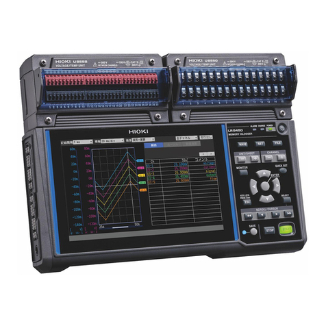
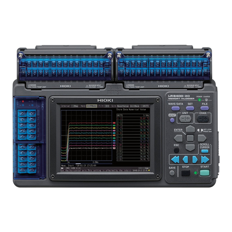
Hioki LR8400-20 User manual

MEMORY HiLOGGER
Measurement Guide
LR8401-20
April 2010 Edition 1 LR8400B981-00 10-04H
LR8402-20
LR8400-20


Introduction
1
Thank you for purchasing the Hioki Model LR8400-20, LR8401-20, LR8402-20
Memory HiLogger.
This Measurement Guide consists of some basic application examples.
Before using the HiLogger, be sure to read the Instruction Manual carefully.
The following documents are provided with the HiLogger. Refer to them as appropriate for your application.
Contents
Introduction
Document Description
1Measurement
Guide
(This document)
Read first.
Offers an introduction to the Memory HiLogger's basic measuring
method for first time users.
2Instruction
Manual Contains explanation and instructions regarding the HiLogger's oper-
ating method and functions.
Operating Outlines and
Screen Configurations Describes the screen types and an overview of
the operating keys. (p. 2)
Measurement Prepara-
tions Describes the preparations for measuring. (p. 7)
Measurement Proce-
dure Describes procedures from pre-measurement in-
spection to observation. (p. 8)
Measuring This is an example of simultaneously measuring
and automatically saving variations in voltage
(CH1) and temperature (CH2) of a 1.5 V battery.
(p. 10)
Viewing Waveforms or
Numerical Values DescribesusingtheHiLoggertoview waveforms
and numerical values. (p. 14)
Observing Data on a
Computer Describes how to observe data with a computer. (p. 18)

Operating Outlines and Screen Configurations
2
Operating Outlines and Screen
Configurations
External Control
Terminals
•Pulseinputs
• Alarm outputs
• External control
(input/output)
• 12-volt output
•AlarmLED
Operating Keys
(Rear) Battery
Compartment
Universal Unit∗Voltage/Temp Unit∗
∗: Input units are installed as specified upon factory shipping.
Display Screen
Front Panel
CHARGE LED
Lights while charg-
ingtheZ1000Bat-
tery Pack.
POWER LED
Lights when
powered on.
AC Adapter Socket POWER Switch
Right Side
USB Cable Port
CF Card Slot Ethernet LAN Cable Connector (RJ-45)
USB Port

Operating Outlines and Screen Configurations
3
Operation Keys
WAVE/DATA
Selects among waveform/nu-
merical screen displays (p. 4).
SET
Displays the Settings screens,
and switches among the screen
tabs with each press (p. 5).
FILE
Displays file information (p. 6).
Choose a screen
Use SCROLL/CURSOR tose-
lect waveform scrolling or A/B
cursormotion,andusethe arrow
keys to scroll or move A/B cur-
sors (p. 15).
Scroll waveforms and
read cursor values
Start and stop measurement.
The LED next to START lights green while
measuring (p. 9).
Start and stop measurement
Press to save data manually.
Saving operations
CH
Select channels.
UNIT
Switches input units.
MONIT
Shows the current input wave-
form and numerical values (data
not stored in internal memory,
CF card, and USB flash drive).
ESC
Cancels changes to settings.
Cursor Keys
Moves the position
of the cursor (blink-
ing selection) on
the screen.
ENTER
Accepts displayed
settings.
Setup and display
Select the item to
change.
Show available set-
ting options.
Select the desired
setting.
Changing screen contents
Apply the new set-
ting, or cancel it.
Disables keypad operations
(Key-Lock function)
Hold the left and right keys
simultaneously for three
seconds to lock and un-
lock other key operations.
Zero Adjust
With the Waveform/Value
or [CH] screen displayed,
press the up and down cur-
sor keys simultaneously.
Basic Key Operations

Operating Outlines and Screen Configurations
4
[Wave] Screen
Measurement data is dis-
played as waveforms.
[Value+Cmnt] Screen
Measurementdataisdisplayedas
numerical values with comments.
[Wave+Calc] Screen
Measurement data is dis-
played as waveforms with cal-
culation results.
[Gauge+Wave] Screen
Measurement data is displayed
as waveforms with gauges.
[Wave+Value] Screen
Measurement dataisdisplayedas
waveforms and numerical values.
[Value] Screen
Measurement data is dis-
played as numerical values.
[Wave+Crsr] Screen
Measurement data is dis-
played as waveforms with cur-
sor values.
Waveform/Numerical Screens
Switches among the
above screens.
Operational informa-
tion is displayedalong
the bottom of the
screen.
The screen switch-
es each time you
press the key. (sev-
en display types)
[Gauge+Wave]
[Wave]
[Wave+Value]
[Value+Cmnt]
[Value]
[Wave+Calc]
[Wave+Crsr]

Operating Outlines and Screen Configurations
5
[CH] Screen
Make input channel settings
while viewing the monitor dis-
play.
[Conv/Calc] Screen
[Comment] Screen
Enter channel comments.
[Setting] Screen
Make settings for recording.
Set numerical calculation,
auto-saving and timers.
[Range] Screen
Make settings while viewing all
channel set.
[Trig & Alm] Screen
Recording criteria (triggering)
and warning sounds can be
set for each channel.
[System] Screen
Configure the system environ-
ment.
Settings Screens
Operationalinformation
is displayed along the
bottom of the screen.
Make these settings to convert
measured values to arbitrary
units for display.
Selects a measurement in-
put unit and its settings.
The screen switch-
es each time you
press the key. (sev-
en display types)
Press the left/right
keys to select be-
tween the Settings
screens.
When a tab is se-
lected with the cur-
sor, the left-right
cursor keys switch
among the setting
screens.

Operating Outlines and Screen Configurations
6
File Screen
View and manage files on the
CF card/USB flash drive.
File Screen
Operational information
is displayed along the
bottom of the screen.

Measurement Preparations
7
Follow these steps to prepare before measuring.
Measurement Preparations
Make the necessary connections to the HiLogger, and turn the power
switch on.
Install the battery pack (option) (as needed)
Rear panel When the battery pack is installed, operation switches to
batterypower during power outages so that measurements
can continue uninterrupted.
2
Connect the measure-
ment input cables
1InputExpansionUnits
(as needed)
If auto-saving to CF card or USB flash drive is disabled, data
is only recorded in internal memory, and is lost when measure-
ment starts again, or about 30 minutes after the HiLogger is
turned off. We recommend keeping auto-saving to CF card en-
abled.
7Insert an optional CF card or
USB flash drive (when saving
data)
5
Connecteachpairofinput
and output terminals
(as needed)
Connect the AC adapter
3
6
Turn the power on.
4
Front
Right
side
Right side
Right side

Measurement Procedure
8
Before measuring, be sure to read the "Operating Precautions" in the
Instruction Manual.
Measurement Procedure
Pre-measurement inspection Read "Pre-Connection Inspection"
in the Instruction Manual.
Connect to the measurement object
Configure settings for measurement
Configure recording settings
on the [Setting] screen.
• Recording interval
• Recording time
• Auto-saving (if used)
Make other settings as neces-
sary.
Configure input channel set-
tings on the [CH] screen.
• Channel selection
• Input type
• Measurement range
Make other settings as neces-
sary.
(continues on next page)

Measurement Procedure
9
Start and finish measuring∗
When continuous recording
([Cont]) is disabled ([Off]),
measurement stops automati-
cally after the set recording
time (there is no need to press
STOP).
* Triggering is used to start and stop measurement by specified criteria, or at specified
times.
Start
Measurement Stop
Measurement
Observation

Measuring
10
This is an example of simultaneously measuring and automatically saving varia-
tions in voltage (CH1) and temperature (CH2) of a 1.5 V battery.
Measuring
1Prepare the Following Before Measuring
Items to prepare
Model LR8400-20,
LR8401-20, LR8402-20
Memory HiLogger
AC Adapter (supplied)
Measurement (input) leads
Thermocouple
CF Card ∗
∗: Hioki option Connect to the
measurement points
Turn the power on
(Right side)
Connect to power outlet
1
2
5Insert a CF card
(Right side)
4
3
Connect a voltage
measurement cable
to CH1, and a K ther-
mocouple to CH2
2Configure Measurement Settings
Make recording timing settings on the [Setting] screen.
1
Setting Example
Record at five-seconds intervals for
one day automatically on the CF card
(p. 12)
Interval: 5sec
Record time: Cont Off, 1 day
Set the recording
interval.
Set the recording
time.
Select 50 or 60 Hz to match
the local line frequency.
Measurement Hints
Filter : When 50 or 60 Hz is selected, longer recording intervals
produce lower cut-off frequencies and better noise sup-
pression.
Recording Time: To measure continuously until you press
STOP, enable continuous recording (Cont: On).
The default settings for the non-framed items can be left as-is. Change as needed.
2
Select
Apply

Measuring
11
Setting Example
Channel: CH1, Input: Voltage, Range: 2V
Channel: CH2, Input: TC, K, Range: 100°C,
Burn Out: Off, RJC: INT
Make input channel settings on the [CH] screen.
Measurement Hints
For maximum resolution, select the most
sensitive range that includes the measured
value.
Settings within the dotted frame affect the vertical axis dis-
play.
Disp Span
Type Position
0 Pos 0% (appears as 0 V at the bottom of the screen)
0 V
2 V
When set as shown at the
left, the vertical axes ap-
pear like this.
0 °C
100 °C
CH1 CH2
1
2
Select
Apply

Measuring
12
If auto-saving to CF card or USB flash drive is not enabled, data is only recorded in inter-
nal memory, and is lost when measurement starts again, or about 30 minutes after the
HiLogger is turned off. We recommend keeping auto-saving to CF card enabled.
Conversion to text (CSV) format can be done later, so we suggest selecting [Waveform(realtime)]
for typical operation.
3To Enable Auto-Save (set saving conditions)
Make these settings on the [Setting] screen.
•Select[Auto Save] (save format) and [Media] as shown
here.
• Optionally enter the [File Name].
•Select[Deleting] or [Split Save] as needed.
Measurement Hints
When the CF card or USB flash drive becomes full while saving:
Enable [Deleting] (set to On) to delete the oldest files and continue saving.
Disable [Deleting] (set to Off) to stop saving when the media is full.
When partial saving is enabled, files are saved at the specified interval.
Select [Split Save] (set to On or Ref time) to set the partition time span.
• Confirm that there is enough free space on the media, and that it is inserted correctly.
• Although real-time saving to USB flash drive is available, we recommend using a CF card for
optimum reliability and data preservation.
• Performance cannot be guaranteed when using storage media other than a Hioki-specified
CF card option.
1
2
Select
Apply
Observation Method Setting State
Save measurement data for later analysis with the
HiLogger or the Logger Utility. Auto save: Waveform(realtime)
Retrieve data from the CF card or USB flash drive for
analysis with Excel. Auto save: CSV(realtime)

Measuring
13
4Start and finish measuring
• Data is recorded to HiLogger memory. It is then automatically saved to the CF card. Recording
stops one day after starting.
• To stop recording early, press STOP.
• To view waveforms or numerical values while measuring, see "Viewing Waveforms or Numer-
ical Values" (p. 14).
Press START.

Viewing Waveforms or Numerical Values
14
This section describes how to view waveforms and numerical values during and
after measurement.
Press WAVE/DATA to display the Waveform/Value screen. The screens toggle each time
the key is pressed. Gauges can be displayed, and numerical values and waveforms can
be viewed simultaneously.
Viewing Waveforms or Numeri-
cal Values
Display Waveforms
[Gauge+Wave] [Wave] [Wave+Value] [Value+Cmnt]
[Wave+Crsr] [Wave+Calc] [Value]
(Screen display switching is available here)

Viewing Waveforms or Numerical Values
15
Viewing a Measurement Waveform
Scrolling the Waveform
Theportionofawaveformthatiscurrently
displayed can be confirmed by the posi-
tion of the scroll bar.
Whole Waveform
Currently Displayed
Earlier Later
Display
Jumps to the latest waveform
Jumps to the waveform beginning
Press both simultaneously
Scroll backward
Fast scroll
backward
Scroll forward
Fast scroll
forward
Show/hide A/B
cursors
Scrolling Methods
Zooming the Waveform View
Specify the time per division for the horizontal axis.
Zooming (Magnifying and Reducing)
the Horizontal Axis
Zooming the Vertical
Axis
Specify the magnification
factor for the vertical axis.

Viewing Waveforms or Numerical Values
16
Measured values can be viewed as numerical values, waveforms and numerical values,
or as numerical values and comments.
Displayed numerical values are those of the current input signals.
To display waveforms and numerical values
To display numerical values and comments
To display numerical values only
View Measurement Values
Select [Wave+Value].
Select [Value+Cmnt].
Channels subject to scaling settings are
displayed with smaller characters.
Select [Value].
Advice
• Use the A/B cursors to view measured values at particular times. See "Displaying Cursor Values" in the
Instruction Manual for details.
• Average, maximum, and minimum values can be calculated and displayed while measuring. See
"Numerical Calculations/Waveform Calculations" in the Instruction Manual for details.

Viewing Waveforms or Numerical Values
17
Data saved by the LR8400-20, LR8401-20, LR8402-20 can be confirmed on the File
screen. It is stored on the CF Card/USB flash drive as follows. The numbers in the file
names are automatically generated sequentially.
View CF Card / USB Flash Drive Contents
Moves to
child folder
Moves to parent
folder File selection Use to delete or rename a file
HIOKI_
LR8400
CONF0001.SET
WAVE0001.MEM
(Settings data folder)
CONFIG
(Waveform data folder)
DATA
MEASUREMENT
WAVE0001.CSV
PICTURE
(Numerical calculation results
folder)
(Screen image folder)
10-03-01
(thefoldernameis the
date of file creation)
MEAS0001.CSV
SCR00001.BMP
ALL
PART
(calculation results
for each split inter-
val when split calcu-
lation is enabled)
MEAS0001.CSV
MEAS0001_1.CSV
MEAS0001_2.CSV
These files are created for
automatic numbering, and
contain no data
(calculation results
from start to stop)
Auto-saved file names are of the form username0001.XXX or AUTO0001.XXX.
When split calculation is en-
abled, both ALL andPART fold-
ersarecreated,withcalculation
results from start to stop stored
in the ”ALL” folder, and calcula-
tion results for each split inter-
val stored in the “PART” folder.

Observing Data on a Computer
18
To analyze data using a spreadsheet program such as Excel, first convert the waveform
(binary) data to text (CSV) format using the HiLogger or Logger Utility program.
This procedure describes how to convert to text format using the Logger Utility.
See the LR8400 Series Instruction Manual for steps to install and start the Logger Utility.
Load the measurement data file (".MEM" extension) from the HiLogger, as follows.
1 Start the Logger Utility.
See the instruction manual for details.
2 Remove the CF card or USB flash drive with the saved mea-
surement data from the HiLogger, and insert it into the com-
puter.
To load data from CF card to a computerwithout removing the CF card from the
HiLogger, select the HiLogger’s USB Drive mode and connect it to a computer
with the USB cable. (See the Instruction Manual for USB Drive mode details.)
3 In the menu bar, click [File] -[Open Waveform File].
The [Open Waveform File] dialog appears.
4 Select the file to load, and click the [Open] button.
Observing Data on a Computer
Converting waveform data to text format
1Obtain Measurement Data
Other manuals for LR8400-20
1
This manual suits for next models
2
Table of contents
Other Hioki Data Logger manuals

Hioki
Hioki LR8431-20 User manual

Hioki
Hioki LR8431-20 User manual
Hioki
Hioki LR5051 User manual

Hioki
Hioki PW3360-30 User manual

Hioki
Hioki LR8450 User manual

Hioki
Hioki Hioki Instruction manual

Hioki
Hioki 3631-20 User manual

Hioki
Hioki LR8450 Instruction manual

Hioki
Hioki 3639-20 User manual

Hioki
Hioki lr5001 User manual

Hioki
Hioki LR5031 User manual
Hioki
Hioki LR8512 User manual

Hioki
Hioki lr5001 User manual

Hioki
Hioki LR8431-20 User manual

Hioki
Hioki HiCORDER MR8880 User manual

Hioki
Hioki 8861 Instruction manual

Hioki
Hioki LR5092-20 User manual

Hioki
Hioki HiLogger 3145-20 User manual
Hioki
Hioki LR8400-20 User manual

Hioki
Hioki PW3365 User manual