List of Figures
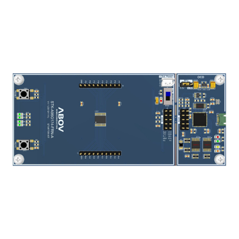
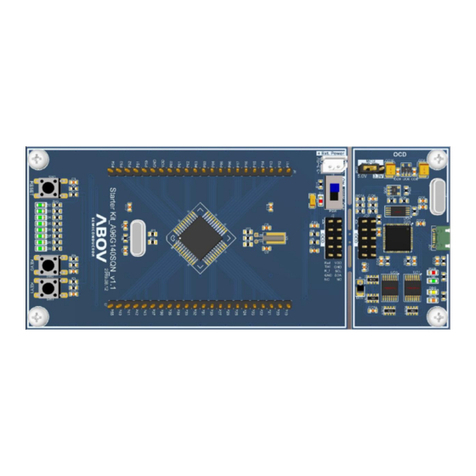
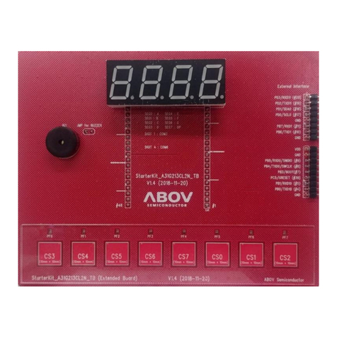
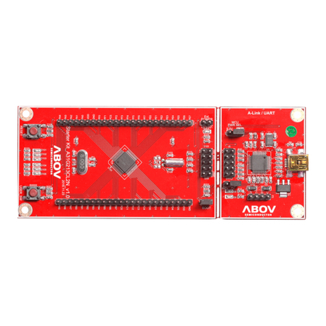
Figure 1. A31T216RLN Starter Kit Board (Hardware) ............................................................................5
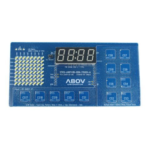
Figure 2. A31T216RLN Shield Board (Hardware) ..................................................................................5
Figure 3. Compiler (Software) .................................................................................................................6
Figure 4. Reference Document on the ABOV Website ...........................................................................7
Figure 5. Window PC and Mini-B Cable .................................................................................................8
Figure 6. Software and Documents at ABOV Semiconductor Website ..................................................9
Figure 7. Starter Kit Board ....................................................................................................................11
Figure 8. Components of A31T216RLN Shield Board ..........................................................................12
Figure 9. Starter Kit Jumper and Switch ...............................................................................................13
Figure 10. Connection of Starter Kit Board and Shield Board ..............................................................14
Figure 11. Starter Kit and USB Connection ..........................................................................................15
Figure 12. Serial Bus Controller Lists at Device Manager ....................................................................16
Figure 13. Project Open in Keil uVision 5 .............................................................................................17
Figure 14. Project Build in Keil uVision 5 ..............................................................................................18
Figure 15. Debugger Settings for Example Project Options .................................................................19
Figure 16. Firmware Download and Verification Result ........................................................................20
Figure 17. Debugging with ABOV A-Link and CMSIS-DAP ..................................................................21
Figure 18. T-type and M-type LEDs for Touch and Display ..................................................................22
Figure 19. Touch/LED Time-division Mode ...........................................................................................23
Figure 20. Touch/LED Independent Mode ............................................................................................24
Figure 21. Touch CH Activation.............................................................................................................25
Figure 22. LED COM/SEG Port Activation............................................................................................26
Figure 23. Touch CH Activation.............................................................................................................27
Figure 24. Sensitivity for Each Channel in Normal Mode .....................................................................28
Figure 25. Sensitivity for Each Channel in Adjust Mode .......................................................................29
Figure 26. CH_SHIELD_DIS, MESH_SHIELD_DIS .............................................................................30
Figure 27. CH_SHIELD_EN, MESH_SHIELD_EN ...............................................................................30
Figure 28. Touch Data Changes according to SUM_COUNT...............................................................31
Figure 29. Base-line Tracking ...............................................................................................................33
Figure 30. Press Threshold and Release Threshold ............................................................................34
Figure 31. Reverse Situation Parameters.............................................................................................35
Figure 32. Debounce Count ..................................................................................................................36
Figure 33. IIR-filter ................................................................................................................................36
Figure 34. Touch/LED Time-division Operation ....................................................................................37
Figure 35. Touch Key Value Assignment...............................................................................................38
Figure 36. Source Code: user.h ............................................................................................................39
Figure 37. Source Code : main() in main.c ...........................................................................................40
List of Tables
Table 1. Shield Board Description .........................................................................................................12
