English
15
• For transporting by vehicle or by any kind
of hoist, 3 lashing or hoisting points are
provided :
■Two at shaft height.
■One on protection ring.
• During transport, rest the front of the
machine on a block of wood.
• Turn off the tap (4) [SEE FIG. 1].
• Refill the water tank from the mains (F)
[SEE FIG. 1] (optional isolating valv ).
• Mark the floor by drawing a line in the
place to be cut.
• Position the machine so that the folded-
down front guide (6) and the blade are
lined up with the mark.
• Start up the motor :
Petrol and Diesel : refer to the
instructions in the manufacturer's service
manual.
Allow the motor to warm up.
• Turn on the water tap (4).
• The locking lever (8) should be down to
move the wheel (7).
• Increase the motor speed to full power.
•
Adjust the travel of the disk by means of the
hand-wheel (7) : a slow descent is
advisable to prevent the motor from stalling.
(1 turn of the handwheel = 1.25 cm).
• Raise the lever (8) when the required
depth has been set.
• Advance the machine gently whilst
ensuring that the front guide and the
blade always follow the mark.
- Automatic v rsion
- Set the potentiometer (23) [Fig. 1] to a
minimum.
- Control the release of the lever to engage
forward motion.
- Push the controller (21) [Fig. 1] forward
(on-position)
- Turn the potentiometer to obtain the
required advance speed
(speed adjustable from 0 to 2 m/min ma .)
- A rational advance speed cannot be set
as this depends on the cutting depth, the
type of cutting wheel and the material to
be cut.We recommend that you do not
make the motor labour uselessly
(characterised by black e haust fumes).
Travel at a regular speed.
Automatic Advanc
For short distances or loading assistance, it
is possible to use the "rapid" automatic
advance without starting up the motor. To
do this:
- raise the machine as far as possible
- Control the release of the lever to engage
forward motion.
- push the controller forward or backward
(if reverse required) and hold it in
position. By releasing the pressure, the
machine stops automatically.
7Starting up
Always pay extreme care and
attention to the preparation of
the machine before starting up
Remove all adjustment tools and
wrenches from floor and
machine
Always keep blade guard in
place
Abundant water cooling =
guaranteed long blade life
•PETROL OR DIESEL MOTOR (refer to
the engine maintenance manual)
•MACHINE WITH ELECTRIC MOTOR
(direction on the sides of the guard).
Check the following :
• Motor power supply : reinforced electric
cable with 4 (3P+E) or 5 (3P+N+E)
conductors 2.5 mm2for lengths less than
100 m.
• Earthing of the machine (mandatory).
• The motor’s direction of rotation must
match the arrow on the disc casing(if the
motor does not rotate in the requisite
direction, invert the 2 feed wires).
■Ensure the fuel is topped up.
Diesel : do not wait until the tank is
empty before filling up. A lack of fuel
risks draining the pump.
■Check the oil level : as the motor
frequently works on an incline, check,
in the horizontal position, that its oil
level never falls below the second line
one the gauge.
■To start up, refer to the engine
instructions.
- Stop switch set to stop.
- Battery: Battery isolation switch
turned on.
Take into account the working
conditions from health and safety
point of wiew.
Use only blades marked with a
maximum operating speed
greater than blade shaft speed
The working area must be
completely cleared, well lit and
all safety hazards removed (no
water or dangerous objects in
the vicinity)
The operator must wear
protective clothing appropriate
to the work he is doing. We
recommend that this includes
both eye and ear protection
Any persons not involved in the
work should leave the working
area
The use of ear protection is
mandatory.
5Ch ck b for starting
Please read the instructions for
use prior to operating the
machine for the first time.
otor off.
Take care about the direction of
rotation which is shown by an
arrow on one of the faces
(direction of rotation on the right
side of the casing)
ake sure the contact faces of
flanges, of blade and the axle are
clean
The disk clamping screw (D) has
a left-hand thread.
For your own safety and for the
protection of other people,
replace all the protective
devices.
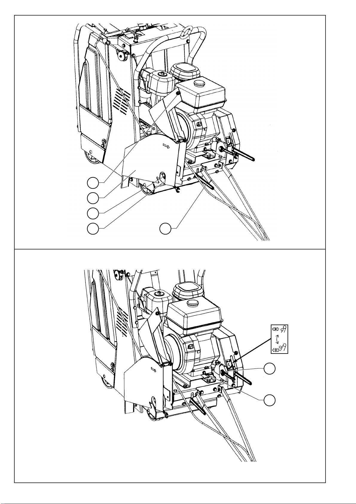
6Fitting th blad
• Lift the front mobile part of the disc
protection housing (A) [see Fig. 2]
(loosen the housing nut (B)).
• Slacken the screw (D) and remove the
smooth plate (C).
• Fit the disk by slotting it into the fi ed
casing.
• Lock the screw (D) firmly using the 18
mm spanner while holding the pin shaft in
position using the 30mm spanner (E)
• Replace the guard (lock nut (B)).
Motor off
Disconn ct th pow r plug
- ELECTRICAL SAFETY :
Operate this machine only on a
supply equipped with a 30 mA
earthed current-limiting circuit-
breaker. Otherwise, consult our
catalogue for appropriate
models.
- Th RCCB must b us d
corr ctly, including t sting it
r gularly. For tools suppli d
with an int gral RCCB in th
cabl or in th mains plug, if
th cabl or plug has b n
damag d, r pairs must b
carri d out by th
manufactur r, on of his
ag nts or by a qualifi d
r pair workshop to avoid any
risks r sulting from rrors.
Danger: risk of injury