Dimas WS 400 Series User manual

DIMAS WS 463
English .................................................. 1
Español ................................................19
Français ...............................................37
Português ...........................................55


Operator’s Manual WS 463
English - 1
Contents
English
Contents
Key to symbols.............................................................. 3
Safety Instructions...................................................... 4
Introduction..................................................................... 6
What is what.................................................................... 7
Technical data................................................................ 8
Cutting capacity............................................................... 8
Cutting speed m/s........................................................... 9
Cutting speed ft/min....................................................... 9
Assembling/Installing equipment................... 10
Wall mounting................................................................ 10
Assembling the saw.................................................... 11
Fit the blade.................................................................... 12
Fit the blade guard...................................................... 13
Operation........................................................................ 14
Before cutting................................................................. 14
Sawing............................................................................... 14

2 - English
Contents Operator’s Manual WS 463
After cutting..................................................................... 14
Maintenance................................................................... 15
EU declaration of conformity............................. 17

English - 3
Operator’s Manual WS 463
Key to symbols
The symbols below are used on the machine and in this
Operator's Manual. It is important that the user
understands the significance of these in order to work with
the machine safely.
Manual
Please read the Operator's Manual carefully and
understand the contents before the machine is started.
Protective equipment
Always wear:
• Approved protective helmet.
• Approved hearing protection.
• Approved protective glasses or a visor, and other
essential safety equipment.
Warning
A large warning triangle with the text “Warning” signifies
that there is a risk of serious personal injury or even
death.
CAUTION
A smaller warning triangle with the text “Note” signifies
that there is a risk of minor personal injury or damage to
the machine.
Remark
A hand with a raised index finger with the text “Attention”
signifies that a described element demands extra
attention.
CE
This symbol indicates that the machine conforms to
applicable EU directives.

4 - English
Operator’s Manual WS 463
Safety Instructions
During the design and production of Dimas products,
great importance is placed on safety, as well as
effectiveness and ease of use. To ensure that the
machine remains safe you must pay attention to the
following points:
WARNING!
This machine is only intended for use
together with a DIMAS PP 355, DIMAS PP
455 and DIMAS RC 455. All other use is
forbidden.
CAUTION
Under no circumstances may the machine be
started without observing the safety
instructions. Should the user fail to comply
with these, Electrolux Construction Products
Sweden AB or its representatives are free
from all liability both directly and indirectly.
Read through these operating instructions and
make sure that you understand the contents
before starting to use the machine. Should
you, after reading these safety instructions,
still feel uncertain about the safety risks
involved you must not use the machine Please
contact your dealer for more information.
• Check that all couplings, connections and hydraulic
hoses are in full working order.
• Make sure that all hoses and electrical cables are
connected to themachine correctly before you start the
machine.
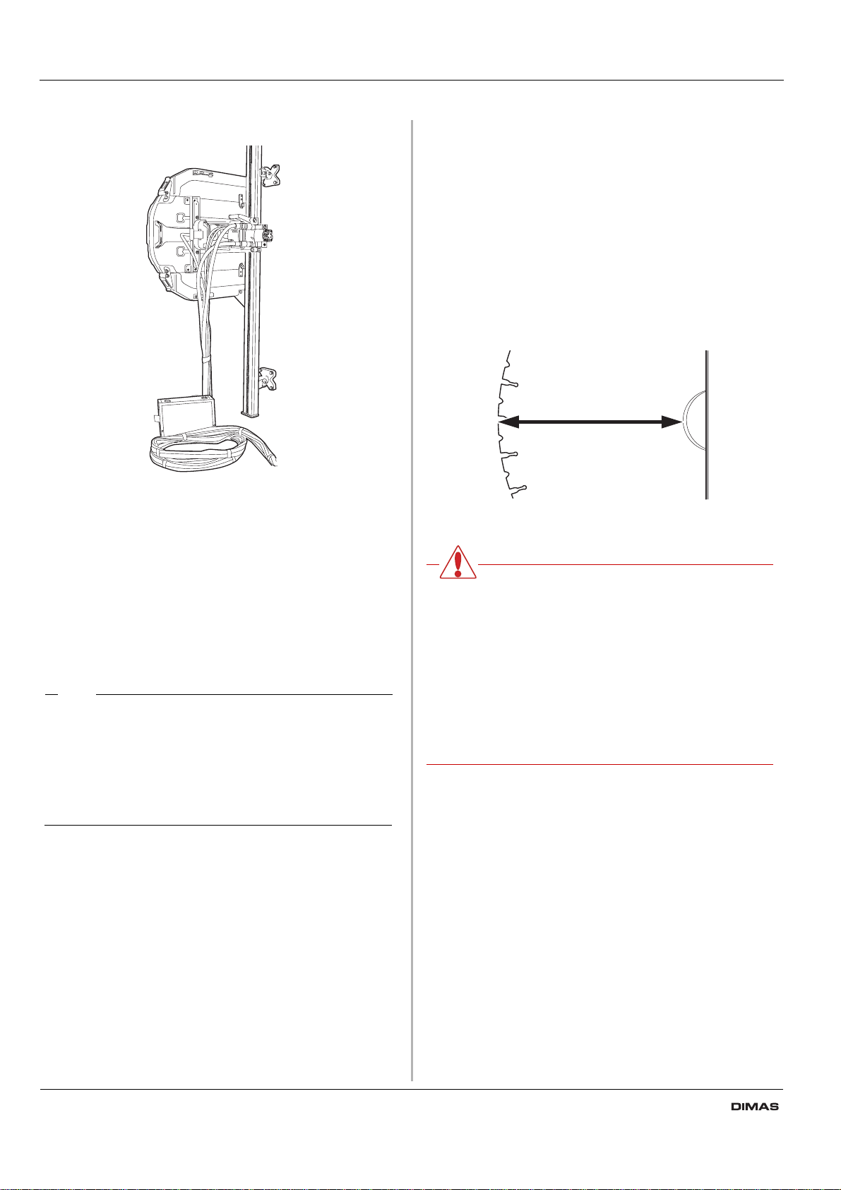
• The safety distance is 4 metres in front of and to the
side of the saw.
• Make sure that there are no persons or animals in the
working area.
• Check that the blade guard is not damaged and that it
has been fitted correctly.
• Never cut without using the blade guard. The
maximum size of saw blade when starting is 1000 mm.
As accessories there are also blade guards for 800,
1240, and 1600 mm blades.
Never remove the blade guard without first shutting off
the hydraulic unit and ensuring that the blade has
finished rotating completely.
• Never disconnect the hydraulic hoses without first
shutting off the hydraulic unit and ensuring the motors
have stopped completely.
• Check the machine, couplings and hydraulic hoses
daily for leakage. A rupture or leak can cause a
”hydraulic fluid injection” in the body or result in other
serious physical injury.
• Do not exceed the specified hydraulic fluid flow or
pressure for the tool being used. Too high pressure or
flow can resulting rupturing
• Never use the hydraulic hoses to lift the saw.
• Do not misuse hoses.
• Do not use hoses that are distorted, worn, or damaged.
• Check that the hoses are connected correctly to the
machine and that the hydraulic couplings lock as
intended before pressurising the hydraulic system. The
couplings are locked by turning the outer sleeve on the
female coupling so that the slot moves away from the
ball.
• Keep the hydraulic hoses and couplings free from dirt.
• Always switch off the power to the hydraulic unit before
moving the equipment.
• Always saw in a manner that permits easy access to
the emergency stop.
• Never leave the machine unsupervised with the engine
running.
• Clearly mark out all cuts to be made before you start
sawing, plan these so they can be carried out without
danger to persons or the machine.
• Check with the construction drawings whether there
are electrical cables, water mains, gas pipes or
drainage pipes within the working area.
• Always check and mark out where gas pipes are
routed. Cutting close to gas pipes always entails
danger. Make sure that sparks are not caused when
cutting in view of the risk of explosion. Remain
concentrated and focused on the task. Carelessness
can result in serious personal injury or death.
• Check that electrical cables within the working area are
not live.
• Hoses that are marked and approved as electrically
non conductive must be used when using hydraulic
tools on or in the vicinity of electrical cables. The use of
other types of hoses can result in serious physical
injury or even death.
• Observe care when lifting. You are handling heavy
parts, which implies the risk of pinch injuries or other
injuries.

English - 5
Operator’s Manual WS 463
• Personal protective equipment according to the
Operator's Manual must always be used and you
should use protective clothing too. Never wear loose
fitting clothes that can catch in moving parts.
• People that need to be in close proximity of the
machine must wear hearing protection as the sound
level when cutting exceeds 85 dB(A).
• Only use blades recommended by Dimas.
• Never saw without coolant. A poorly cooled blade can
cause segments to come loose from the blade. The
water coolant also binds concrete dust.
• Never use a damaged or worn blade.
• Do not use the machine if it is not working properly.
• Regulations for the prevention of accidents, and other
general safety and occupational health regulations,
must always be followed.
• Store the machine in a locked space away from
children and adults untrained in use of the machine.
• Firmly secure or anchor concrete blocks that have
been cut loose. The heavy weight of cut material can
cause extensive damage if it is not moved under
controlled conditions.
• Always check the back of the wall where the blade
comes out when cutting through. Secure, cordon off
and make sure that no people can be injured or
materials damaged.
• Make sure that there is always another person close at
hand when you use the machines, so that you can call
for help if an accident should occur.
WARNING!
Always use approved protective clothing
and approved protective equipment when
using the machine. Protective clothing and
protective equipment cannot eliminate
accident risks, but by using the right
clothes and equipment you can reduce the
seriousness if an accident should occur.
Ask your dealer about approved and
recommended protective clothing and
protective equipment.

6 - English
Operator’s Manual WS 463
Introduction
WS 400 is a series of completely new complete wall saws
from Dimas. The intention when developing the DIMAS
WS 400 series has been to produce a very light yet
powerful wall saw that is easy for one person to handle
using modern production methods and high performance
materials.
Among the new features on the WS 400 series is the
possibility to secure the blade radially on the saw. As the
saw unit is mounted on a carriage using a quick-action
mounting instead of directly on the rail, assembly of the
saw is significantly easier.
To utilises the input effect in the best possible way the
saw is mounted on Dimas' the latest rail. This is a very
stable rail, which allows the saw to be controlled more
precisely, which in turn results in more efficient cutting. As
the equipment's component parts work with small losses
and as the blade is moved in 50 mm closer to the rail
compared to earlier models, which has also resulted in a
saw with an extremely compact design and at the same
time as efficiency has increased.
Complete saw equipment consists of
One saw
One Rail 1.2 m
One Rail 2 m
Four standard wall mountings
One rail holder
One connector
One blade guard 800 or one blade guard 1000
One blade guard guide
One tool kit
One bottle of Dimas oil 150
Transport cases for the different units The saw carriage is
mounted on both the long and short rails at the factory to
make cutting as easy as possible.
As a large part of the sawing work consists transporting,
the saw equipment is supplied in specially produced
cases. The cases provide good protectionduring transport
and reduced the number of packages that need to be
moved between the workplaces, which makes the work
more effective

English - 7
Operator’s Manual WS 463
What is what
The saw consists of the following component parts:
1. Saw Carriage
The separate saw carriage is one of the new features
of the WS 400-series. The separate saw carriage
results in a system that is both simpler and quicker to
fit than other saws. The saw carriage is supplied
mounted and adjusted on the rail from the factory. The
saw carriage features two levels to facilitate mounting
the rail straight when cutting horizontally and vertically.
2. Locking handle
Used to lock the saw unit in the saw carriage.
3. Saw unit
Houses the feed motors for the saw's travel feed and
the arm's feed as well as two slipping clutches that
prevent the saw from being damaged if it should jam.
4. Speed valve
The speed of the saw motor is controlled with this
valve. There are three positions. The speed of rotation
to be used depends on the blade size used (See the
cutting speed table)
5. Cutting arm
The cutting arm allows blades up to 1000 mm (40") to
be used as the start blade. The cutting arm can be
rotated through 360 degrees, which gives great
freedom when planning the cut. As the cutting arm has
been moved in 50 mm (2") closer to the rail compared
to earlier saw models, the forces that affect the saw
are reduced appreciably, which gives straighter cuts
and less friction losses between the blade body
and cut.
6. Blade guard guide
The blade guard is suspended from this. When the
saw' is to be lifted the blade guard guide acts as a
handle. The blade guard guide also acts as a
protective cage for the saw.
7. Rail
The machine is supplied with two rails, one 2 m
(6.55 ft) and one 1.2 m (3.95 ft). A saw carriage is
mounted on each rail at the factory.
8. Hub-unit
Hub unit is another new feature on the WS 400 series.
The hub unit is mounted on the blade before the blade
is fitted on the saw and in doing so permits easier
assembly of the blade on the saw. The hub unit is
ready for flush cutting.
9. Thrust washer
Locks the saw blade on the hub unit.
10.Hydraulic hose connections
The hydraulic flow in the large hoses drives the blade
while the hydraulic flow in the smaller hoses drives the
direction of the saw.
The hoses connected to the saw's small female
couplings (closest to the arm) drive the arm for feeding
and removal while those connected to the small male
couplings (furthest from the arm) drive the saw along
the rail.
11.Water connector
Water coolant for the blade is connected here. In
addition to cooling blade, the water also binds the dust.
1
2
3
45
6
7
8
9
10
11

8 - English
Operator’s Manual WS 463
Technical data
*
Remark
The stated weight for the two rails refers to
one rail with the saw carriage fitted. To find the
weight of just the rail, you must deduct the
weight of the saw carriage from the weight
stated.
Cutting capacity
WS 400 series has the possibility to cut with following
sizes of blades:
800 mm (32") blade diameter__________ 330 mm (13")
1000 mm (40") blade diameter_________ 430 mm (17")
1200 mm (47") blade diameter_________ 530 mm (21")
1600 mm (63") blade diameter ________ 730 mm (29")
However, the largest possible blade size from start is 1000 mm
(40").
We recommend that DIMAS wall saw blades are used.
WARNING
Under no circumstances may
modifications be made to the machine
without written permission from Electrolux
Construction Products Sweden AB. Non
approved modifications putyou and others
at risk of serious or fatal injuries.
Electrolux Construction Products Sweden
AB bears no responsibility for operations
that do not conform to these instructions.
Weight saw carriage:_____________ 3.7kg (8.15 lbs)
Weight, saw unit ________________ 22 kg (48.5 lbs)
Weight, blade guard:_____________ 15 kg (33 lbs)
Weight, rail 1200 mm (47")____________ 12.2 kg (26.9 lbs)
Weight, rail 2000 mm (79")____________ 17.2 kg (37.9 lbs)
Hydraulic fluid flow, max. _____________ 65l/min (17 gal/min)
Pressure, max._____________________ 230 bar (3340 psi)
Travel feed ________________________ hydraulic
Blade motion ______________________ hydraulic

English - 9
Operator’s Manual WS 463
Cutting speed m/s
Cutting speed ft/min
Blade diameter (mm) 600 700 800 1000 1200 1500 1600
Spindle speed 1400 rpm
pos.3 44 51
Spindle speed 1000 rpm
pos. 2 42 52
Spindle speed 630 rpm
pos.1 40 49 53
Blade diameter inch 24 28 32 40 47 59 63
Spindle speed 1400 rpm
pos.3 8797 10263
Spindle speed 1000 rpm
pos. 2 8378 10472
Spindle speed 630 rpm
pos.1 7752 9731 10391

10 - English
Operator’s Manual WS 463
Assembling/Installing
equipment
Wall mounting
There are two types of wall mounting available for the
DIMAS WS 400 series. One, the standard wall mounting,
which is supplied on delivery, and secondly the universal
swivel wall mounting.
CAUTION
The DIMAS WS 400 series may only be used
with the two wall mountings described above.
Older Dimas wall mountings are similar to the
new standard wall mounting, but have a longer
base. This mounting must not be used with the
WS 400 series as there is a risk that the arm
catches on the base of the mounting.
Use the universal wall mounting when cutting doors,
cutting flush, cutting at angles and stair cutting as well as
groove cutting. If you only require an everyday straight cut
you use the fixed mounting.
Fit the universal wall mounting for the required cutting
method (See the separate manual).
Fit the standard wall mounting as set out below:
1. Mark off the cutting line and mark off the expander
bolts holes 164 mm (6.5") from the cutting line.
2. Drill 15 mm holes for the M12 expander bolts.
3. Hang the wall mountings loosely from the expander
bolts, using M6S 12 x 70 or similar.
4. Place the rail in the wall mountings and tighten the
compression washers.
5. Check that the rail sits correctly in the slots in the wall
mountings.
6. Adjust the distance between the cutting line and the
wall mounting. The distance between the edge and the
inner face of the saw cut should be 89 mm (3.5").
Tighten the expander bolts.
CAUTION
Only use the connectors supplied when
purchasing the saw as older connectors are
not designed for the WS 400 series.
165 mm
6,5"
89 mm
(3.5")

English - 11
Operator’s Manual WS 463
Assembling the saw
1. Fit the saw body in the saw carriage by lifting the saw
body into position. When the saw is lifted into position,
the locking handle moves up into an intermediate
position. In this position the saw remains in the saw
carriage without it needing to be held. However, it is
not sufficiently secured to begin cutting.
*
Remark
With a vertical cut it is usually simpler to
assemble the saw in the saw carriage with the
handle upwards on the rail.
2. To secure the saw, lift the locking handle towards the
saw until the handle locks in the upright position.
WARNING!
To cut without the saw securely assembled
in the saw carriage and rail is associated
with mortal danger.
3. When the saw unit is mounted in the saw carriage, the
hydraulic hoses should be fitted. There are two types
of hydraulic hoses for the saw:
The four thin hoses control the feed motors, i.e. the
saw's travel feed on the rail and the feed - removal of
the blade. The two thick hoses drive the blade.
The couplings should be wiped clean to reduce the risk
of leakage before the hoses are fitted. Both the thin
and thick hoses are locked by turning the outer sleeve
on the female coupling so that the groove in the sleeve
moves away from the ball.
4. Connect the incoming water hose and the hydraulic
hoses to a hydraulic unit.
WARNING!
This machine is only intended for use
together with a DIMAS PP 345 and DIMAS
RC 348. All other use is forbidden.

12 - English
Operator’s Manual WS 463
Fit the blade
On the Dimas WS 400-series the blade is fitted in an
entirely new way. The new mounting permits, in addition
to the tradition way of securing the blade, the possibility to
secure the blade radially both quickly and easily:
1. Start by removing any dirt from the contact surfaces on
the blade flange and blade.
2. Check the blade's direction of rotation. The blade
should rotate anticlockwise seen from the saw side
and the released part of the diamond should lie in the
blade's direction of rotation.
3. Screw together the thrust washer, blade and blade
flange hub.
4. Hang the blade with the blade flange and blade flange
hub fitted on the cutting arm (blade is not shown in the
figure).
5. Carefully turn the blade until the hub locks onto the
cutting arm.
6. Press in the blade spindle into the cutting arm at the
same time as the blade is rotated carefully. When the
blade spindle can no longer be pressed in by hand it
should be tightened using the supplied 18-spanner
until it is properly secured (tightening torque 30-
40 Nm).
WARNING!
Exercise care when assembling the blade
so that it does not risk becoming loose
when cutting.

English - 13
Operator’s Manual WS 463
Fit the blade guard
1. Guide on the blade guard carriage between the stays
on the blade guard.
2. Lift the blade guard over the blade and hang the guard
in the blade guard holder on the saw. Exercise care so
that the runners on the blade guard are positioned in
the slots on the water block.
3. Lock the blade guardby pulling the handle out from the
guard. When the guard needs to be removed, press
the handle in towards the guard.

14 - English
Operator’s Manual WS 463
Operation
Before cutting
Enclose the area to be cut so that unauthorised persons
can not be injured or disturb the operator.
Check that the blade guard is not damaged or broken. A
broken or damaged blade guard must never be used.
Check the oil level in the cutting unit. Adjust the speed
valve on the saw motor to the correct position, depending
on the blade diameter. (See the Cutting capacity table).
CAUTION
A higher speed than the recommended speed
can result in personal injury and damage to
the equipment.
If cutting is to begin in another position than where the
saw unit is located, run the saw unit to the start position.
Sawing
Always start by cutting a pilot cut. This is done by feeding
the blade 3-7 cm (1.2"-2.8"). Now make the pilot cut. The
cut should not be made at maximum speed, but with care
in order to obtain a straight cut and with that a basis for
the next cut.
When the pilot cut is finished, a deeper cut can be made.
The depth of these is determined from instance to
instance and depends on factors such as hardness of the
concrete, existence of reinforcing bar, etc.
As the rail is symmetrical, the saw unit can be turned to
make a new cut on the other side of the rail. The c-c
measurement will then be 328 mm. In this way a cut piece
is obtained that is in an easily handled size, making it
easier to remove from the workplace.
*
Remark
When the saw's is turned on the rail, the water
jet will be positioned away from the blade and
will spray in the opposite direction, possibly up
towards the ceiling.
Stop cutting
Once cutting is completed, remove the blade from the wall
and shut down the blade rotation and the water flow.
Shut down the hydraulic unit.
After cutting
Cleaning
The saw should be cleaned once cutting is finished. It is
important to clean all the saw equipment. It is a good idea
to disconnect the water hose from the pivot arm and use
this to wash down the saw unit, rail, blade guard, wall
mounting. If necessary you can also use a dish-brush or
the like to clean the equipment. Do not use a high
pressure washer to clean the saw.
Dismantling the saw
1. Allow the motor to stop completely.
2. Shut off and disconnect the incoming water to the
hydraulic unit.
3. Disconnect the incoming mains cable from the
hydraulic unit.
4. Disconnect the hydraulic hoses and the water hose
from the saw unit.
5. The other steps are done in the reverse order to
assembling.

English - 15
Operator’s Manual WS 463
Maintenance
In addition to the daily maintenance such as cleaning and
lubrication, the machine must be serviced. When it is time
for a service the text “time for service” is shown on the
display on the remote control. After 50 hours of cutting,
the machine should be serviced at an accredited Dimas
workshop. The saw should then be serviced after every
100 hours of operation. The service is important so that as
the user you have a machine that works as effectively as
possible for a long time.
Oil change cutting arm:
There is an oil plug for draining the oil located on the
cutting arm. This plug should be cleaned when changing
the oil. The new oil is filled through the hole where the oil
plug sits.
The cutting arm contains 1 dl of Dimas Oil 150, a trans-
mission oil of the type EP 150. The oil should be replaced
for the first time in connection with the first service. A 1 dl
bottle of oil is supplied when the machine is new.
*
Remark
Remember than oil can pose a hazard to
health and the environment.
Lubricating the feed motors:
There are two grease nipples on each saw unit. The feed
motors can be lubricated through these. (We recommend
lubricating with VEIDEC POWER LUBE or equivalent
grease every 50 hours of operation)
Adjusting the guide wheels:
In order for the saw to run stably and saw a straight cut,
the four guide wheels must rest against the rail and not
have too much play. When there is too much play
between the saw carriage and rail the guide wheels must
be adjusted:
The two marked guide wheels have eccentric axles and
by turning these the carriage is tightened onto the rail.

16 - English
Operator’s Manual WS 463
Start by loosening the marked nuts (1) with the supplied
special tool. Now loosen the two stop screws (2). When
these are loose, adjust the guide wheels (3) against the
rail by turning them towards the rail so the play is taken
up. Hold the guide wheels and screw in the stop screw.
Now screw on the nuts to secure the guide wheels in the
new position.
Grease the blade spindle:
In order for the blade spindle to be fitted as easily as
possible, it may be necessary to grease the hexagonal
blade spindle. At the same time check that the hexagon is
not damaged.
Adjust the saw carriage:
As the saw wears, after a number of hours working, it can
be a good idea to ensure that the saw sits firmly in the saw
carriage and rail. If not, the handle probably needs
adjusting:
Loosen the marked (1) socket headed screw (one on each
side of the handle). Now turn the eccentric axles (2) with
the help of the supplied special tool until the axle lies tight
against the saw. Now tighten the socket headed screw.
2
1
3
1
2

English - 17
Operator’s Manual WS 463
EU declaration of conformity
Dimas AB, Box 2098, 550 02 Jönköping, Sweden, tel: 036-570 60 00, hereby declares that
its WS 463 wall saw, from serial number 01001 onwards, is manufactured in compliance
with the Council's machinery directive 98/37/EC, low-voltage directive 73/23/EEC and
EMC directive 89/336/EEC, including subsequent amendments, and that the following
standards have been used for guidance: EN 55 014-1, EN 55 014-2, EN 61 000-3-2, EN 50
144-1, EN 13 862.
Jönköping 2005-01-01
Christer Carlberg
Managing Director

18 - English
Operator’s Manual WS 463
This manual suits for next models
1
Table of contents
Languages:
Other Dimas Saw manuals

Dimas
Dimas TS 350 F - 02 User manual

Dimas
Dimas FS 500 F User manual

Dimas
Dimas WS 350 User manual

Dimas
Dimas FS 500 F User manual

Dimas
Dimas CS 2512 User manual

Dimas
Dimas WS 345 User manual

Dimas
Dimas TS 100 R User manual

Dimas
Dimas FS 300 C User manual

Dimas
Dimas WS 462 User manual

Dimas
Dimas FS 400 User manual