Dinel DLM-35 User manual

Read carefully the instructions published in this manual before the rst use of the level meter. Keep the manual
at a safe place. The manufacturer reserves the right to implement changes without prior notice.
průmyslová elektronika

1 . Basic description .........................................................................................................................4
2 . Variants of level meters ...............................................................................................................5
3 . Dimensional drawing ...................................................................................................................6
4 . Installation and putting into operation .........................................................................................8
5 . Installation instructions ................................................................................................................8
6 . Electrical connection .................................................................................................................10
7 . Control elements .......................................................................................................................11
8 . Function and status indication ...................................................................................................11
9 . Settings .....................................................................................................................................12
10 . Order code ..............................................................................................................................14
11 . Correct specication examples ...............................................................................................14
12 . Accessories .............................................................................................................................15
13. Safety, protections, compatibility and explosion proof ............................................................15
14 . Use, manipulation and maintenance .......................................................................................16
15 . General, conditions and warranty ...........................................................................................16
16 . Marking of labels .....................................................................................................................16
17. Technical specications...........................................................................................................19
18 . Packings, shipping and storage ..............................................................................................23

DLM–35 © Dinel, s.r.o.
3
The capacitative level meters DLM® are intended for continuous level measurement of liquid
and bulk solids in tanks, vessels, sumps or silos, hoppers etc. They are comprised of a housing
with electronic module and measuring electrodes. The electronic part converts the size of the
capacity to the current signal (4 ... 20 mA) or voltage signal (0 ... 10 V).Level meters are made
in several modications of measuring electrodes (rod and rope). The electrodes can be covered
by an insulating coating in case level measurement of adhesive, aggressive or electrically
conductive media. Rod electrodes are also available in a version with reference (coaxial) tube for
level measurement of liquids in tanks made from non-conductive material.
Level meters are produced in the following performances: N – for non-explosive areas,
NT – high temperature for non-explosive areas, Xi – Explosion proof – intrinsically safe for hazard-
ous (explosive) areas and XiM – Explosion proof – intrinsically safe for use in mines with methane
or ammable dust presence danger (see technical specications). There are high temperature per-
formance NT, XiT, XiMT available. DLM are oered in variants with various types of process con-
nection (metric and pipe thread, pressure thread NPT).
To ensure maximum safety of control processes, we have dened the following safety instructions
and information. Each instruction is labelled with the appropriate pictogram.
This symbol informs you about particularly important instructions for installation and operation of
equipment or dangerous situations that may occur during the installation and operation. Not observing
these instructions may cause disturbance, damage or destruction of equipment or may cause injury.
This symbol indicates particularly important characteristics of the device.
This symbol indicates helpful additional information.
Alloperations described in thisinstruction manual havetobe carried outby trained personnel
or by an accredited person only. Warranty and post warranty service must be exclusively
carried out by the manufacturer.
Improper use, installation or set-up of the sensor can lead to crashes in the application.
The manufacturer is not responsible for improper use, loss of work caused by either direct
or indirect damage, and for expenses incurred at the time of installation or during the period
of use of the level sensors.

4
© Dinel, s.r.o. DLM–35
• DLM–35_–20 Uncoated rod electrode for level measurement of bulk-solids (cement, our,
sand, plastic granulate) and electrically non-conductive liquids (vegetable oil,
diesel fuel, petrol).
Maximum electrode length 1 m.
• DLM–35_–21 Coated rod electrode (insulation FEP) for level measurement of water and
other electrically conductive liquids. Can also be used for polluted liquids in
metal tanks, concrete sumps, etc.
Maximum electrode length 1 m.
• DLM–35_–22 Coated rod electrode (insulation PFA) with enhanced resistance to
permeation (diusion) of vapours and gases. For level measurement of
water and other electric conductive liquids in the food, pharmaceutical and
chemical industries. In the short term can be used for high temperature
applications (e.g. hot steam sanitation), or for volatile aggressive liquids, etc.
Maximum electrode length 1 m.
• DLM–35_–25 like DLM-35_-22 but higher pressure resistance at high temperature. Suitable
for high temperature applications (hot steam) etc.
• DLM–35_–30 Uncoated rod electrode used for level measurement of bulk-solids
(cement, our, sand, plastic granulate) and electrically non-conductive liquids
(vegetable oil, diesel fuel, petrol).
Maximum electrode length 3 m.
• DLM–35_–31 Coated rod electrode (FEP) for level measurement of water and other
electrically conductive liquids. Can also be used for polluted liquids in metal
tanks, concrete sumps, etc.
Maximum electrode length 3 m.
• DLM–35_–40 Uncoated rod electrode with reference tube (coaxial electrode) for
accurate level measurement of unpolluted electrically non-conductive liquids
(oils, diesel fuel, petrol). The measurement is not dependent on the tank
shape and on the presence of objects in close proximity to the reference tube.
Maximum electrode length 1 m.
• DLM–35_–41 Coated rod electrode with reference tube(coaxial electrode) for accurate
level measurement of unpolluted electrically conductive liquids in plastic and
glass tanks. The measurement is not dependent on the tank shape and on
the presence of objects in close proximity to the reference tube. Maximum
electrode length 1 m.
• DLM–35_–50 Uncoated rope electrode with weight for level measurement of bulk-solids
(e.g. grains, sand, gravel, cement, etc.).
Maximum electrode length 6 m.

DLM–35 © Dinel, s.r.o.
5
** D: Tri-Clamp CI34 (ø 34 mm)
Tri-Clamp CI50 (ø 50,5 mm)
* Type of threads: G 1''; G 3/4''; M27x2;
M30x1,5; NPT 3/4
All dimensions are in mm
64
22
35
16
36
6,5
E100 - E1000
10
10
8
15
42
DLM – 35_ – 20 DLM – 35_ – 21, 22, 25
DLM – 35_ – 30 DLM– 35_ – 31
thread *
E100 - E1000
10
10
6
4646
E100 - E3000
E100 - E3000
8
Measuring electrode
Insulating bushing
Sensor housing
End of sensor
Cable gland
DLM – 35_ – 50
22
105
E500 - E6000
50 10
3
5
Process connection
Tri-clamp
D **

6
© Dinel, s.r.o. DLM–35
DLM – 35_ – 40 DLM – 35_ – 41
Variant “A” with short
stainless steel gland
Variant “B” with plastic
threaded cable gland Variant “C”
with connector M12
+
-
6,5
12
18
12
20
+
-
15
20
+
-
M12
13
Variant “H” with cable gland for
protected hoses - for using in an
outdoor area or in area with increased
moisture.
Variant “V” with plastic cable
gland with spiral relief - for case
of increased mechanical wear on the
cable.
Spiral relief
Protective hose
(ø 13 mm)
High tempera-
tures variants
Variant “D” with
dustproof cable outlet

DLM–35 © Dinel, s.r.o.
7
Please follow next 3 steps:
• Level meters with coated electrode have protection cover at the end of electrode, which is
necessary take down before mounting.
• Level meters mount in vertical position to upper lid of tank or reservoir by welding ange, xing
nut or Clamp ange.
• For mounting level meter to the metal tank or hopper, it is not necessary to ground the housing
again.
• In case of installation in concrete sumps or silos, it is appropriate to install the level meter onto
a metallic auxiliary construction (console, lid, etc.) and then connect with metal constantly
submerged object, eventually with steel armouring.
• For level measurement of material in plastic and glass vessels by level meter without reference
tube is necessary to connect grounding screw at housing with auxiliary electrode which is
xed in an appropriate manner to the outer casing of vessels (or at the inner wall). Material
of auxiliary electrode must be selected with consideration for the working environment and
properties of measured material.
For types : DLM-35_-20, 21, 22, 25, 30, 31
E- the length of electrode [mm]
- select so that the end of the
electrode is dipped min. 20 mm
below the lowest measured level
h- the distance from the
bottom - min. 20 mm
a- the distance from the wall -
min. approx. E/20
d- the diameter of auxiliary
tube vessel - min. 40 + E/20
(smaller dimension has to be
discussed with producer)
auxiliary electrode
width = min. 30 mm
(necessary only for non-
metal vessels)
Fig. 1: Installation of level meters with rod electrode
Auxiliary measuring
vessel (bypass)

8
© Dinel, s.r.o. DLM–35
b
For types : DLM-35_-40, 41
h - distance from bottom - min.
20 mm with regard to possibility of the
presence of heavier fractions (water)
in petroleum products
k -the distance from the wall -
optional
Fig. 2: Installation of level meter with reference tube
For types : DLM-35_-50
connection to the
armouring
E - electrode length [mm] - select so that the end of the electrode would be at least 20 mm under the lowest measured leve
h - distance from bottom - min. 100 mm
a - distance from wall - min. E/20, otherwise select the largest (as far as possible from the wall), towards the middle
between the wall and vertical drain
concrete silo
metal tank
Fig. 3: Installation of level meter with rope electrode

DLM–35 © Dinel, s.r.o.
9
The positive pole of the supply voltage (+U) is connected to the brown wire BN or pin connector
no.1, the negative pole (0 V) is connected to the blue wire BU or pin connector no. 3 and output
voltage (Uout) to the black wire BK or pin connector no. 4.
Wiring diagrams are provided in the gures below 4 and 5.
Note: In case of strong ambient electromagnetic interference, paralleling of conductors with power
distribution, or for the distribution to distance over 30 m, we recommend using shielded cable.
Level meters DLM-35 with type of cable outlet A, B, V or H are connected to assessing units
permanently connected by PVC cable. Variant diagrams are provided on page 7.
Level meters DLM-35 with connection method type C (see page 7) are connected to assessing
units by means of a connector socket with compression cable (length 2 or 5 m), or by means of
a connector socket without cable (see accessories), the connector is not part of the sensor. In this
case the cable is connected to the inside pins of the socket according to gure 6. The recommended
diameter of this cable is 4 to 6 mm (the recommended cross-sectional area is 0.25 to 0.5 mm²).
The length of the cable for the Xi, XiT, XiM, XiMT variations must be selected with respect to the
maximum permitted parameters (usually inductance and capacity) of the outside intrinsically safe
circuit of supply units IRU-420.
Electrical connection can only be made when de-energized!
The source of the power voltage must comprise of a stabilised safe low power source with
galvanic separation. In the event that a switch-mode power supply is used, it is essential
that its construction effectively suppresses common mode interference on the secondary
side. In the event that the switch-mode power supply is equipped with a PE safety terminal, it
must be unconditionally grounded! Spark-safe devices type DLM–35Xi (XiT, XiM, XiMT) must
be powered from a spark-safe power source meeting the above-mentioned requirements.
+
-
+
-
0 V (3)
+U (1)
BN ()1
BU ()2
mA +U
0V
V
+U
0V
U
Uout
V
+U
0V
U
Uout
mA +U
0V
+U
0V
BN (1)
BU (2)
BK (3)
+U
0V
BN (1)
BU (3)
BK (4)
BN ()1
BU (3)
BN ()1
BU ()2
BK (3)
BN ()1
BU (3)
BK (4)
BN ()1
BU ()2
mA +U
0V
mA +U
0V
BN ()1
BU (3)
BN ()1
BU ()2
mA +U
0V
V
+U
0V
U
Uout
V
+U
0V
U
Uout
mA +U
0V
+U
0V
BN (1)
BU (2)
BK (3)
+U
0V
BN (1)
BU (3)
BK (4)
BN ()1
BU (3)
BN ()1
BU ()2
BK (3)
BN ()1
BU (3)
BK (4)
BN ()1
BU ()2
mA +U
0V
mA +U
0V
BN ()1
BU (3)
Fig. 4: Connection diagrams and interior view
of connector of level meter DLM (variant - I)
Fig. 5: Connection diagrams and interior view
of connector of level meter DLM (variant - U)
0 V (3)
+U (1)
Fig. 6: Inside of the
connector socket
(variant “C”)
Uout (BK)
0V (BU)
+U (BN)
Legend:
(1...)– terminal numbers
connector sockets
BN –brown
BU –blue
BK –black
Uout (4)

10
© Dinel, s.r.o. DLM–35
Due to the possible occurrence of an electrostatic charge on the non-conductive parts of
the sensor, it is necessary to ground all sensors intended for use in environments with
an explosion hazard DLM–35Xi (XiT, XiM, XiMT). This can be performed by grounding el.
conductive tanks or el. conductive tank lids, and in the case of el. non-conductive tanks
using and grounding an auxiliary plate electrode PDE-27.
In the event that the level meter (sensor) is installed in an outdoor environment at a
distance greater than 20 m from the outdoor switchboard, or from an enclosed building,
it is necessary to supplement the electrical cable leading to the level meter (sensor) with
suitable overvoltage protection.
In the event of strong ambient electromagnetic interference, paralleling of conductors with
power distribution, or for distribution to distances over 30 m, we recommend using a shielded
cable and grounding the shielding on the side of the power source.
Cable gland
or connector
Orange LED
Sensitive spot +Sensitive spot -
Green LED
spot
• input to setting mode
• direct setting to value 4 mA (0 V)
• decrease in values along dened steps
spot
• input to setting mode
• direct setting to value 20 mA (10 V)
• increase in values along dened steps
Fig. 7: Top view of level sensor
LED indicator colour function
"RUN" green
Measuring function indicator
ashing – (repeats according to period of measuring approx. 0.5 s)
– correct function of measuring the level
dark – incorrect installation or malfunction.
LED is also not illuminated in limit setting mode.
alternating ashing green and orange LED – incorrectly set limits
"STATE" orange
Settings indication
slow ashing – indication of setting the lower limit
rapid ashing – indication of setting the upper limit
permanent shine – the level meter is prepared to conrm the limit
setting by means of mag. pen
3x short ashes – setting conrmation
simultaneous shine of green and orange LED – during touching
the mag. pen, when the limit setting is conrmed

DLM–35 © Dinel, s.r.o.
11
Setting the device is done after its installation by touching the magnetic pen to sensitive spots
and . The setting process is indicated by the orange LED “STATE”.
Connect the level meter to the power supply. Using a measuring device or associated device, check
its output - current or voltage.
Basic method of setting the measuring range of the level meter. At this setting, the level in the tank
must be brought to the minimum and then maximum level.
1. Empty the tank to the level of the minimum measured level. (To achieve the required linearity
the end of the electrode has to be dipped, see Fig.1.)
2. Touch the magnetic pen for approx. 5 seconds on the sensitive spot of the level meter.
After 3 seconds, the LED indicator “STATE” starts to ash slowly. Keep the magnetic pen in
touch with the sensitive spot and after 2 more seconds direct setting of the value 4 mA (0 V) is
performed.
3. Then put away the magnetic pen from sensitive spot and wait for permanent shine of the orange
LED indicator “STATE”.
4. After light up of the orange LED indicator “STATE”, conrm the setting by short touch of the
magnetic pen on the sensitive spot . After simultaneous light up of both LED indicators
“STATE” and “RUN” it is possible to put away the magnetic pen. The LED indicator “STATE” will
briey ash 3x to conrm the setting of the limit.
1. Fill the tank to the level of the maximum measured level.
2. Touch the magnetic pen for approx. 5 seconds on the sensitive spot of the level meter.
After 3 seconds, the LED indicator “STATE” starts to ash rapidly. Keep still the magnetic pen in
touch with the sensitive spot and after 2 more seconds direct setting of the value 20 mA (10 V)
is performed.
3. Then put away the magnetic pen from sensitive spot and wait for permanent shine of the orange
LED indicator “STATE”.
4. After light up of the orange LED indicator “STATE”, conrm the setting by short touch of the
magnetic pen on the sensitive spot . After simultaneous light up of both LED indicators
“STATE” and “RUN” it is possible to put away the magnetic pen. The LED indicator “STATE” will
briey ash 3x to conrm the setting of the limit.
5. If both LED indicators “STATE” and “RUN” begin ashing in alternating fashion, it means that
the level meter cannot distinguish between the selected levels (limits are incorrectly set) - it is
necessary to redo the settings.
This setting is used if it is not possible to bring the level to the minimum or maximum level. After
setting of any two limit values, the electronics of the level meter automatically calculates the full
measuring range 4 to 20 mA (or 0 to 10 V).

12
© Dinel, s.r.o. DLM–35
1. Bring the level in the tank to any known (determinable) level, best close to the minimum
measured level.
2. Touch the magnetic pen for approx. 3 seconds on the sensitive spot of the level meter.
After 3 seconds, the LED indicator “STATE” starts to ash slowly and now put away the magnetic
pen from the sensitive spot.
3. At the moment when the LED indicator “STATE” starts ashing slowly, by touching the
magnetic pen on spots and it is possible to set the output value by stepping,
which is calculated according to the formula:
- for current output ... I out = 4 + (0.16 x height of level in %) [mA]
- for voltage output ... U out = 0.1 x height of level in % [V]
(If the magnetic pen is kept on the sensitive spot, the setting step gradually increases.)
4. After reaching the lower output value, put away the magnetic pen from sensitive spots and wait
for permanent shine of the orange LED indicator “STATE”.
5. After light up of the orange LED indicator “STATE”, conrm the setting by short touch of the
magnetic pen on the sensitive spot . After simultaneous light up of both LED indicators
“STATE” and “RUN” it is possible to put away the magnetic pen. The LED indicator “STATE” will
briey ash 3x to conrm the setting of the limit.
1. Bring the level in the tank to a known (determinable) level, best when close to the maximum
measured level.
2. Touch the magnetic pen for approx. 3 seconds on the sensitive spot of the level meter.
After 3 seconds, the LED indicator “STATE” starts to ash rapidly, and now put away the
magnetic pen from the sensitive spot.
3. At the moment when the LED indicator “STATE” starts ashing rapidly, by touching the
magnetic pen on spots and it is possible to set the output value by stepping,
which is calculated according to the formula:
- for current output ... I out = 4 + (0.16 x level height in %) [mA]
- for voltage output ... U out = 0.1 x level height in % [V]
(If the magnetic pen is kept on the sensitive spot, the setting step gradually increases.)
4. After reaching the upper output value, put away the magnetic pen from sensitive spots and wait
for permanent shine of the orange LED indicator “STATE”.
5. After light up of the orange LED indicator “STATE”, conrm the setting by short touch of the
magnetic pen on the sensitive spot . After simultaneous light up of both LED indicators
“STATE” and “RUN” it is possible to put away the magnetic pen. The LED indicator “STATE” will
briey ash 3x to conrm the setting of the limit.
6. If both LED indicators “STATE” and “RUN” begin ashing in alternating fashion, it means
that the level meter cannot distinguish between the selected levels - it is necessary either to
decrease the level for setting the lower output value or increase the level for setting the upper
output value.

DLM–35 © Dinel, s.r.o.
13
DLM–35N–20– M27–I–B E200 cable 5 m
(N) non-explosive areas; (20) uncoated cylindrical electrode;(M27) process connection by thread M27;(I) output
current;(B) plastic threaded cable gland;(E200) electrode length 200 mm.
DLM–35N–21–G3/4–U–C E580
(N) non-explosive areas; (21) coated bar electrode (FEP); (G3/4) process connection by thread G3/4”;(U) output
voltage;(C) connector; (E580) electrode length 580 mm.
DLM–35N–40–M30–I–H E900
(N) non-explosive areas; (40) uncoated rod electrode with reference tube; (M30) process connection by thread M30;
(I) output current;(H) cable gland for protective hose;(E900) electrode length 900 mm.
DLM–35XiT–20– M27–I–B E200 cable 5 m
(XiT) high-temperature conf. for explosive environments;(20) uncoated cylindrical electrode; (M27) process
connection by thread M27;(I) output current;(B) plastic threaded cable gland;(E200) electrode length 200 mm.
DLM–35N–22– Cl50–U–A E200 cable 5 m
(N) non-explosive areas; (22) coated bar electrode (PFA); (Cl50) process connection Tri-clamp (ø 50,5 mm); (U) output
voltage; (A) short stainless steel gland; (E200) electrode length 200 mm.
process connection:
DLM –35
electrode length in mm
– – –– E
type of output:
I –current (4 ... 20 mA)
U – voltage (0 ... 10 V)
connection method:
A – short stainless steel gland
(+ cable length)
B – plastic threaded cable gland
(+ cable length)
C – connector (socket not included
with sensor, recommended type -
see accessories.)
D – metal dust proof terminal
(+ cable length)
V – plastic cable gland with spiral
(+ cable length)
H – plastic cable gland for protec-
tive hose (+ cable length)
type and performance of electrode:
mech. performance:
cable – cable length in m
N – non-explosive areas
NT – high temperature performance
Xi – for explosive environments
XiM – for mining environments
XiT – high-temperature conf. for explosive environments
XiMT – high-temperature conf. for mining environments
20 – rod, uncoated, length 0.1 ... 1 m
21 – rod, coated (FEP), length 0.1 ... 1 m
22 – rod, coated (PFA), length 0.1 ... 1 m
25 – like 22, but higher pressure and mechanical resistance
at high temperatures
30 – rod, uncoated, length 0.1 ... 3 m
31 – rod, coated (FEP), length 0.1 ... 3 m
40 – rod, uncoated with ref. tube, length 0.1 ... 1 m
41 – rod, coated (FEP) with ref. tube, length 0.1 ... 1 m
50 – rope with weight, uncoated, length 1 ... 6 m
G1 – pipe thread G 1”
G3/4 – pipe thread G 3/4”
M27 – metric thread M 27x2
M30 – metric thread M 30x1.5
NPT – pressure thread NPT 3/4
Cl34 – Tri-clamp (ø34 mm)
Cl50 – Tri-clamp (ø 50,5 mm)

14
© Dinel, s.r.o. DLM–35
optional – for a surcharge
(see catalogue sheet of accessories)
• cable (over the standard length 2m)
• connector socket (type ELWIKA or ELKA)
• normal steel welding ange or stainless steel
welding ange
• protective hose (for type of cable outlet H)
• stainless steel xing nut
• various types of seals (PTFE, Al, etc.)
standard – included in the level sensor price
• 1 pcs. magnetic pen MP-8
• 1 pcs. seal (asbestos free) *
The level sensor is equipped with protection against electric shock on the electrode, reverse polarity,
output current overload, short circuit and against current overload on output.
Protection against dangerous contact is provided by low safety voltage according to EN
33 2000- 4- 41. Electromagnetic compatibility is provided by conformity with standards EN 55022 / B,
EN 61326-1, EN 61000-4-2 to -8.
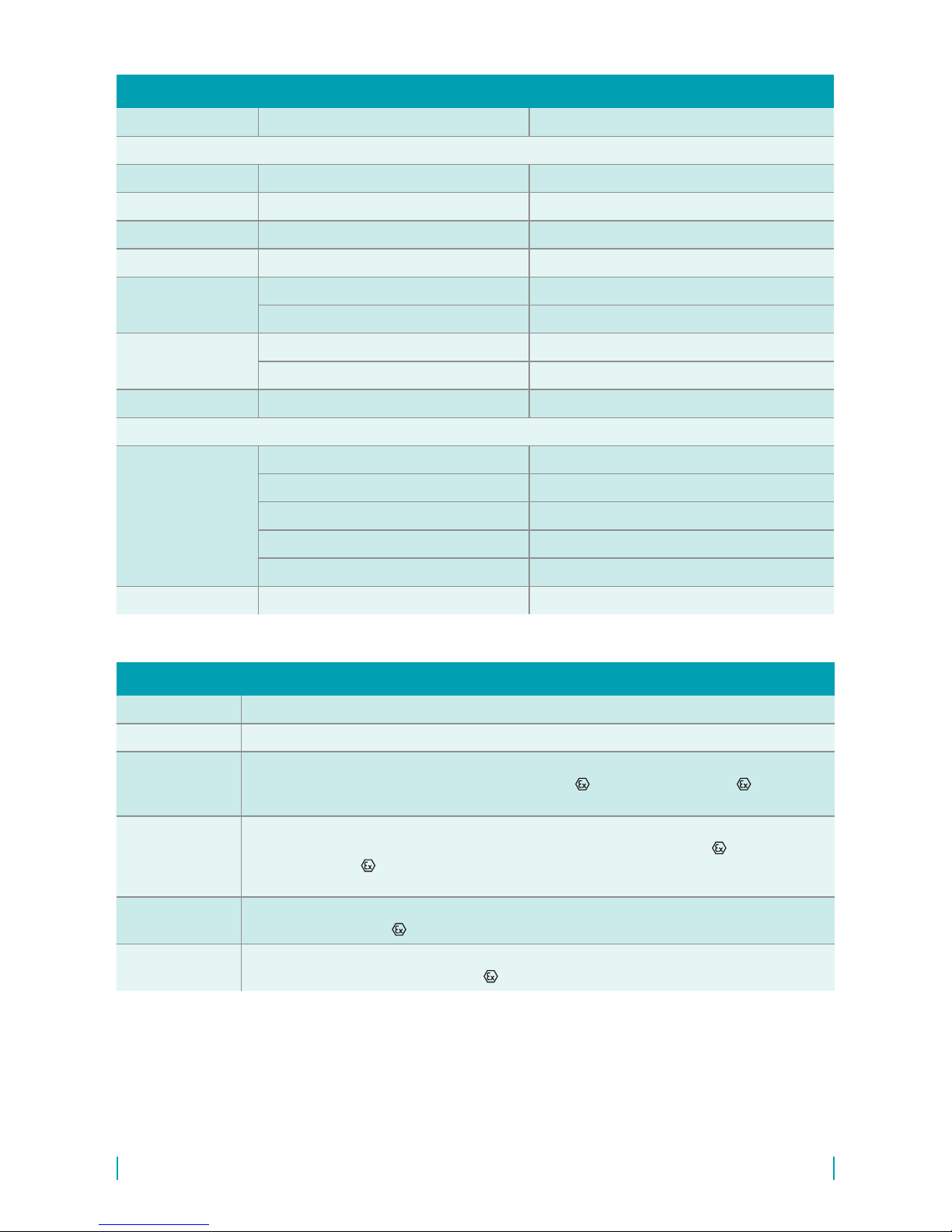
Explosion proof DLM–35Xi (XiT, XiM, XiMT) is provided by conformity with standards EN 60079-0,
EN 60079-11, EN 60079-26.
Explosion proof DLM–35Xi (XiT, XiM, XiMT) is veried FTZÚ – AO 210 Ostrava – Radvanice:
FTZÚ 16 ATEX 0140X.
A declaration of conformity was issued for this device in the wording of Act No. 90/2016 Coll., as
amended. Supplied electrical equipment matches the requirements of valid European directives for
safety and electromagnetic compatibility.
Level meters DLM-35Xi(XiT, XiM, XiMT) are intended for connection to approved spark-safe power
supply unit circuits (of insulating transducers) with galvanic separation. In the event that devices
without galvanic separation are used (Zener barriers), it is necessary to balance the potential
between the sensor, resp. level meter and the barrier grounding location.
The limit output parameters of spark-safe units (insulating transducers) must correspond to the limit
input parameters of the level meter. When assessing spark-free safety of circuits, it is necessary
to also take into consideration the parameters of the connected cable (namely its induction and
capacity).
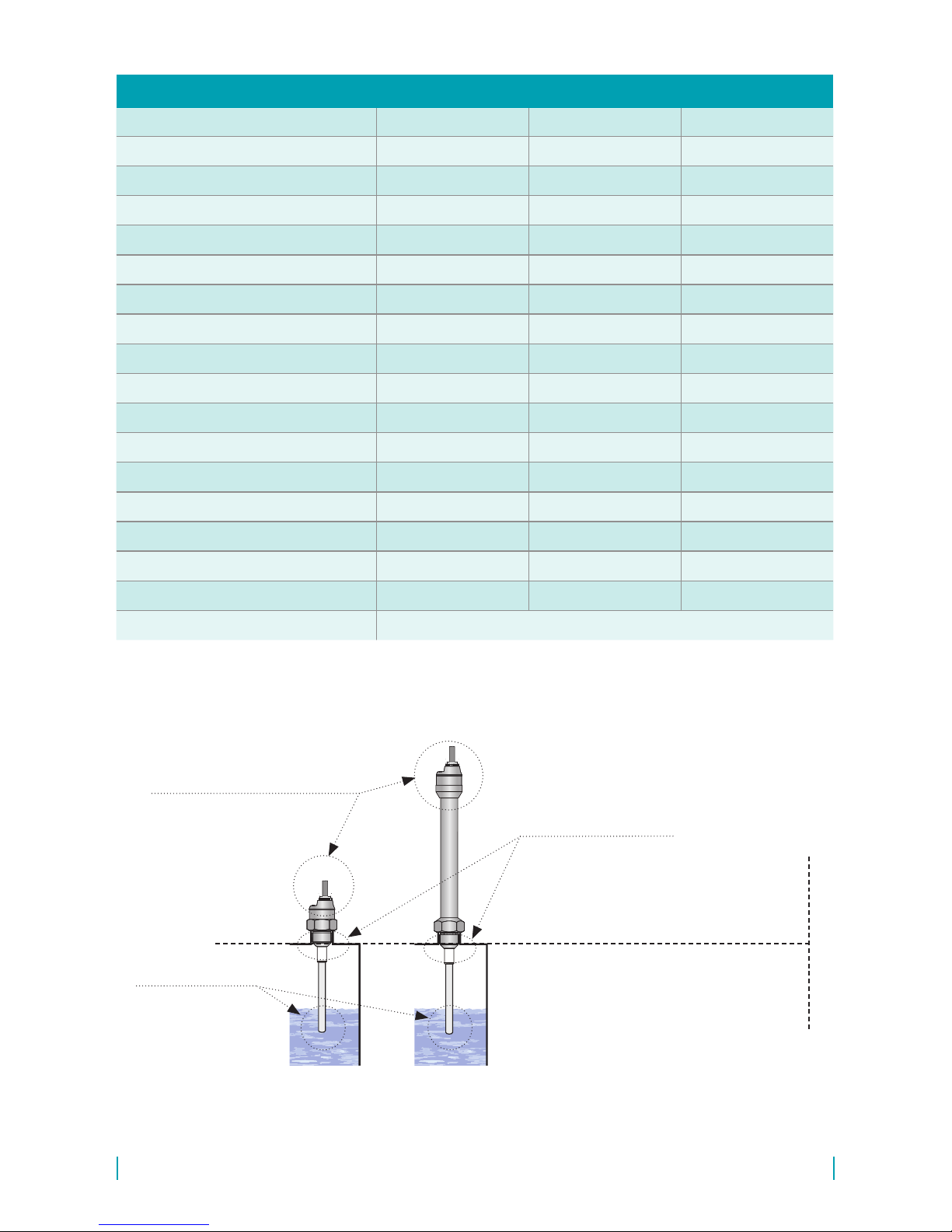
The DLM-35Xi conguration may be located in zone 0 or zone 20. With the DLM-35XiT conguration
it is only possible to located the electrode part in zone 0 and in zone 20, and then the head with the
electronics in zone 1 or zone 21.
Ambient temperature: Tamb = -40°C to +75°C.
The temperature of the measured material according to the variant conguration, see chapter
"Technical parameters". The maximum temperature of the electrodes equals the temperature of the
measured material.
Variant DLM–35XiMT it is necessary to observe that temperature of any surface of apparatus,
when coal dust can from a layer, do not exceed 150°C.
* Pressure resistance - see the table in
the accessories datasheet in the "seals
and gaskets".

DLM–35 © Dinel, s.r.o.
15
The level meter does not require any personnel for its operation. Maintenance of this equipment
consists in verication of integrity of the level meter and of the supply cable.
Dinel, s.r.o. guarantees for the period of three (3) years that the product has the characteristics as
mentioned in the technical specication.
Dinel, s.r.o. is liable for defects ascertained within the warranty period and were claimed in writing.
This guarantee does not cover the damages resulting from misuse, improper installation or incorrect
maintenance.
This guarantee ceases when the user or the other person makes any changes on the product or the
product is mechanically or chemically damaged, or the serial number is not readable.
The warranty certicate must be presented to exercise a claim.
In the case of a rightful complaint, we will replace the product or its defective part. In both cases, the
warranty period is extended by the period of repair.
It is forbidden to perform any modications or interventions into the DLM–35 level meter
without manufacturer’s approval. Any repairs must only be carried out by the producer or
authorized service organisations.
Installation, commissioning, operation and maintenance of the DLM–35 level meter has to
be carried out in accordance with this instruction manual; the provisions of regulations in
force regarding the installation of electrical equipment have to be adhered to.
Labels for device of the type DLM–35N(NT)-__-__-I-_-__:
Symbol of producer: logo Dinel®
Internet address: www.dinel.cz
Country of origin: Made in Czech Republic
Connection scheme and labelling of wires: +U, 0 V
Type of level meter: DLM–35N(T)-__-__-I-_-__
E_____
Cable length: Cable: _ _ m
Serial number: Ser. No.: ______ – (from the left: production year, serial production number)
Output current range: U = 9 ... 34 V =
Supply voltage range: I = 4 ... 20 mA
IP6_
0V
+U
1(bn)
3(bu) I = 4 ... 20 mAU = 9 ... 34 V t = -40 ... +85 °C
a
DLM-35N-__-__-I-_-__ E_____ Cable:__m No.: ______
Dinel
www.dinel.cz
Made in Czech Republic
Délka112mm-výška12mm
Štítekprovarianty DLM 35N-__-__-I-_-__-
IP6_
0V
+U
1(bn)
3(bu) I = 4 ... 20 mAU = 9 ... 34 V t = -40 ... +85 °C
a
DLM-35NT-__-__-I-_-__ E_____ Cable:__m No.: ______
Dinel
www.dinel.cz
Made in Czech Republic
Štítekprovarianty DLM 35NT-__-__-I-_-__-
IP6_
0V
+U
1(bn)
3(bu) I = 4 ... 20 mAU = 9 ... 34 V t = -40 ... +85 °C
a
DLM-35N-__-__-I-_-__ E_____ Cable:__m No.: ______
Dinel
www.dinel.cz
Made in Czech Republic
Délka112mm-výška12mm
Štítekprovarianty DLM 35N-__-__-I-_-__-
IP6_
0V
+U
1(bn)
3(bu) I = 4 ... 20 mAU = 9 ... 34 V t = -40 ... +85 °C
a
DLM-35NT-__-__-I-_-__ E_____ Cable:__m No.: ______
Dinel
www.dinel.cz
Made in Czech Republic
Štítekprovarianty DLM 35NT-__-__-I-_-__-

16
© Dinel, s.r.o. DLM–35
Labels for device of the type DLM–35N(NT)-__-__U-_-__:
Symbol of producer: logo Dinel®
Contact: Dinel, s.r.o., U Tescomy 249, 760 01 Zlín, Czech Republic, www.dinel.cz
Connection scheme and labelling of wires:+U, 0 V
Type of level meter: DLM–35Xi(XiT)-__-__-I-_-__ E______
Cable length: Cable: _ _ m
Serial number: Ser. No.: ______ – (from the left: production year, serial production number)
Mark of non-explosive device:
variant (Xi): II 1 G Ex ia IIB T4 Ga; II 1 D Ex ia IIIC T120°C Da
variant (XiT): II 1/2 G Ex ia IIB T4 Ga/Gb; II 1/2 D Ex ia IIIC T120°C Da/Db
Supply voltage range:
I = 4 ... 20 mA
Limit parameters: Ui = 30 V =, Ii = 132 mA; Pi = 0,99 mW; Ci = 35 nF; Li = 10 μH
Ambient temperature range: ta= -40 ... +75 °C
Number of certicate of intrinsic safety: FTZÚ 16 ATEX 0138X
Protection class: IP6_; Compliance mark:
Number of authorized person supervising over the quality system: 1026
Electro-waste take-back system mark:
IP6_
U =0...10V
out
U = 12 ... 34 V t = -40 ... +85 °C
a
DLM-35N-__-__U-_-__ E_____ Cable:__m No.: ______
Dinel
www.dinel.cz
Made in Czech Republic
Délka112mm-výška12mm
Štítekprovarianty DLM 35N-__-__-U-_-__-
UUout
U
0V
V
1(bn)
3(bu)
4(bk)
IP6_
U =0...10V
out
U = 12 ... 34 V t = -40 ... +85 °C
a
DLM-35NT-__-__U-_-__ E_____ Cable:__m No.: ______
Dinel
www.dinel.cz
Made in Czech Republic
Štítekprovarianty DLM 35NT-__-__-U-_-__-
UUout
U
0V
V
1(bn)
3(bu)
4(bk)
Ambient temperature range: ta = -40 ... +85 °C
Protection class: IP6_ (see. Protection class according to electrical connection)
Compliance mark:
Electro-waste take-back system mark:
IP6_
U =0...10V
out
U = 12 ... 34 V t = -40 ... +85 °C
a
DLM-35N-__-__U-_-__ E_____ Cable:__m No.: ______
Dinel
www.dinel.cz
Made in Czech Republic
Délka112mm-výška12mm
Štítekprovarianty DLM 35N-__-__-U-_-__-
UUout
U
0V
V
1(bn)
3(bu)
4(bk)
IP6_
U =0...10V
out
U = 12 ... 34 V t = -40 ... +85 °C
a
DLM-35NT-__-__U-_-__ E_____ Cable:__m No.: ______
Dinel
www.dinel.cz
Made in Czech Republic
Štítekprovarianty DLM 35NT-__-__-U-_-__-
UUout
U
0V
V
1(bn)
3(bu)
4(bk)
Symbol of producer: logo Dinel®
Internet address: www.dinel.cz
Country of origin: Made in Czech Republic
Connection scheme and labelling of wires: +U, Uout, 0 V
Type of level meter: DLM–35N(T)-__-__U-_-__
E______
Cable length: Cable: _ _ m
Serial number: Ser. No.: ______ – (from the left: production year, serial production number)
Supply voltage range: U = 12 ... 34 V =
Output voltage range: Uout = 0 ... 10 V
Ambient temperature range: ta = -40 ... +85 °C
Protection class: IP6_ (see. Protection class according to electrical connection)
Compliance mark:
Electro-waste take-back system mark:
Labels for device of the type DLM–Xi(XiT):
Délka112mm-výška12mm
Štítekprovarianty DLM 35Xi-__-__-I-_-__-
Štítekprovarianty DLM 35XiT-__-__-I-_-__-
No.: ______
DLM 35Xi-__-__-I-_-__- E_____ Cable:__m
No.: ______
DLM 35XiT-__-__-I-_-__- E_____ Cable:__m
II1 GExiaIIBT/2 4Ga/Gb
II1 DExia II T °C/2 I C 120 Da/Db
FTZÚ 16 ATEX 0138X
No.: ______
E_____ Cable:__m
II1GExiaIIBT4Ga
II1DExia II T °CI C 120 Da
FTZÚ 16 ATEX 0138X
0V
+U
1(bn)
3(bu) 0V
+U
1(bn)
3(bu) 0V
+U
1(bn)
3(bu) 0V
+U
1(bn)
3(bu)
0V
+U
1(bn)
3(bu) 0V
+U
1(bn)
3(bu) 0V
+U
1(bn)
3(bu) 0V
+U
1(bn)
3(bu) I 4 ... 20 mA=
U= V
i30
t = - 0...+ 5 °C
a47
P = mW
i0,99
L = 10 uH
i
C = nF
i35
I = 1 mA
i32
I 4 ... 20 mA=
U= V
i30
t = - 0...+ 5 °C
a47
P = mW
i0,99
L = 10 uH
i
C = nF
i35
I = 1 mA
i32
IP6_
1026
IP6_
1026
Dinel
Dinel, s.r.o.
U Tescomy 249
760 01 Zlín
Czech Republic
www.dinel.cz
Dinel
Dinel, s.r.o.
U Tescomy 249
760 01 Zlín
Czech Republic
www.dinel.cz
Štítekprovarianty DLM 35XiM-__-__-I-_-__-
Štítekprovarianty DLM 35XiMT-__-__-I-_-__-
No.: ______
DLM 35XiM-__-__-I-_-__-E_____ Cable:__m
No.: ______
DLM 35XiMT-__-__-I-_-__- E_____ Cable:__m
I M1ExiaIMa
FTZÚ 16 ATEX 0138X
No.: ______
E_____ Cable:__m
I M1ExiaIMa
FTZÚ 16 ATEX 0138X
0V
+U
1(bn)
3(bu) 0V
+U
1(bn)
3(bu) 0V
+U
1(bn)
3(bu) 0V
+U
1(bn)
3(bu)
0V
+U
1(bn)
3(bu) 0V
+U
1(bn)
3(bu) 0V
+U
1(bn)
3(bu) 0V
+U
1(bn)
3(bu) I 4 ... 20 mA=
U= V
i30
t = - 0...+ 5 °C
a47
P = mW
i0,99
L = 10 uH
i
C = nF
i35
I = 1 mA
i32
I 4 ... 20 mA=
U= V
i30
t = - 0...+ 5 °C
a47
P = mW
i0,99
L = 10 uH
i
C = nF
i35
I = 1 mA
i32
IP6_
1026
IP6_
1026
Dinel
Dinel, s.r.o.
U Tescomy 249
760 01 Zlín
Czech Republic
www.dinel.cz
Dinel
Dinel, s.r.o.
U Tescomy 249
760 01 Zlín
Czech Republic
www.dinel.cz

DLM–35 © Dinel, s.r.o.
17
Labels for device of the type DLM–Xi(XiT):
Délka112mm-výška12mm
Štítekprovarianty DLM 35Xi-__-__-I-_-__-
Štítekprovarianty DLM 35XiT-__-__-I-_-__-
No.: ______
DLM 35Xi-__-__-I-_-__- E_____ Cable:__m
No.: ______
DLM 35XiT-__-__-I-_-__- E_____ Cable:__m
II1 GExiaIIBT/2 4Ga/Gb
II1 DExia II T °C/2 I C 120 Da/Db
FTZÚ 16 ATEX 0138X
No.: ______
E_____ Cable:__m
II1GExiaIIBT4Ga
II1DExia II T °CI C 120 Da
FTZÚ 16 ATEX 0138X
0V
+U
1(bn)
3(bu) 0V
+U
1(bn)
3(bu) 0V
+U
1(bn)
3(bu) 0V
+U
1(bn)
3(bu)
0V
+U
1(bn)
3(bu) 0V
+U
1(bn)
3(bu) 0V
+U
1(bn)
3(bu) 0V
+U
1(bn)
3(bu) I 4 ... 20 mA=
U= V
i30
t = - 0...+ 5 °C
a47
P = mW
i0,99
L = 10 uH
i
C = nF
i35
I = 1 mA
i32
I 4 ... 20 mA=
U= V
i30
t = - 0...+ 5 °C
a47
P = mW
i0,99
L = 10 uH
i
C = nF
i35
I = 1 mA
i32
IP6_
1026
IP6_
1026
Dinel
Dinel, s.r.o.
U Tescomy 249
760 01 Zlín
Czech Republic
www.dinel.cz
Dinel
Dinel, s.r.o.
U Tescomy 249
760 01 Zlín
Czech Republic
www.dinel.cz
Štítekprovarianty DLM 35XiM-__-__-I-_-__-
Štítekprovarianty DLM 35XiMT-__-__-I-_-__-
No.: ______
DLM 35XiM-__-__-I-_-__-E_____ Cable:__m
No.: ______
DLM 35XiMT-__-__-I-_-__- E_____ Cable:__m
I M1ExiaIMa
FTZÚ 16 ATEX 0138X
No.: ______
E_____ Cable:__m
I M1ExiaIMa
FTZÚ 16 ATEX 0138X
0V
+U
1(bn)
3(bu) 0V
+U
1(bn)
3(bu) 0V
+U
1(bn)
3(bu) 0V
+U
1(bn)
3(bu)
0V
+U
1(bn)
3(bu) 0V
+U
1(bn)
3(bu) 0V
+U
1(bn)
3(bu) 0V
+U
1(bn)
3(bu) I 4 ... 20 mA=
U= V
i30
t = - 0...+ 5 °C
a47
P = mW
i0,99
L = 10 uH
i
C = nF
i35
I = 1 mA
i32
I 4 ... 20 mA=
U= V
i30
t = - 0...+ 5 °C
a47
P = mW
i0,99
L = 10 uH
i
C = nF
i35
I = 1 mA
i32
IP6_
1026
IP6_
1026
Dinel
Dinel, s.r.o.
U Tescomy 249
760 01 Zlín
Czech Republic
www.dinel.cz
Dinel
Dinel, s.r.o.
U Tescomy 249
760 01 Zlín
Czech Republic
www.dinel.cz
Size of labels 112 x 12 mm, the size shown does not correspond to reality.
Délka112mm-výška12mm
Štítekprovarianty DLM 35Xi-__-__-I-_-__-
Štítekprovarianty DLM 35XiT-__-__-I-_-__-
No.: ______
DLM 35Xi-__-__-I-_-__- E_____ Cable:__m
No.: ______
DLM 35XiT-__-__-I-_-__- E_____ Cable:__m
II1 GExiaIIBT/2 4Ga/Gb
II1 DExia II T °C/2 I C 120 Da/Db
FTZÚ 16 ATEX 0138X
No.: ______
E_____ Cable:__m
II1GExiaIIBT4Ga
II1DExia II T °CI C 120 Da
FTZÚ 16 ATEX 0138X
0V
+U
1(bn)
3(bu) 0V
+U
1(bn)
3(bu) 0V
+U
1(bn)
3(bu) 0V
+U
1(bn)
3(bu)
0V
+U
1(bn)
3(bu) 0V
+U
1(bn)
3(bu) 0V
+U
1(bn)
3(bu) 0V
+U
1(bn)
3(bu) I 4 ... 20 mA=
U= V
i30
t = - 0...+ 5 °C
a47
P = mW
i0,99
L = 10 uH
i
C = nF
i35
I = 1 mA
i32
I 4 ... 20 mA=
U= V
i30
t = - 0...+ 5 °C
a47
P = mW
i0,99
L = 10 uH
i
C = nF
i35
I = 1 mA
i32
IP6_
1026
IP6_
1026
Dinel
Dinel, s.r.o.
U Tescomy 249
760 01 Zlín
Czech Republic
www.dinel.cz
Dinel
Dinel, s.r.o.
U Tescomy 249
760 01 Zlín
Czech Republic
www.dinel.cz
Štítekprovarianty DLM 35XiM-__-__-I-_-__-
Štítekprovarianty DLM 35XiMT-__-__-I-_-__-
No.: ______
DLM 35XiM-__-__-I-_-__-E_____ Cable:__m
No.: ______
DLM 35XiMT-__-__-I-_-__- E_____ Cable:__m
I M1ExiaIMa
FTZÚ 16 ATEX 0138X
No.: ______
E_____ Cable:__m
I M1ExiaIMa
FTZÚ 16 ATEX 0138X
0V
+U
1(bn)
3(bu) 0V
+U
1(bn)
3(bu) 0V
+U
1(bn)
3(bu) 0V
+U
1(bn)
3(bu)
0V
+U
1(bn)
3(bu) 0V
+U
1(bn)
3(bu) 0V
+U
1(bn)
3(bu) 0V
+U
1(bn)
3(bu) I 4 ... 20 mA=
U= V
i30
t = - 0...+ 5 °C
a47
P = mW
i0,99
L = 10 uH
i
C = nF
i35
I = 1 mA
i32
I 4 ... 20 mA=
U= V
i30
t = - 0...+ 5 °C
a47
P = mW
i0,99
L = 10 uH
i
C = nF
i35
I = 1 mA
i32
IP6_
1026
IP6_
1026
Dinel
Dinel, s.r.o.
U Tescomy 249
760 01 Zlín
Czech Republic
www.dinel.cz
Dinel
Dinel, s.r.o.
U Tescomy 249
760 01 Zlín
Czech Republic
www.dinel.cz
Symbol of producer: logo Dinel®
Contact: Dinel, s.r.o., U Tescomy 249, 760 01 Zlín, Czech Republic, www.dinel.cz
Connection scheme and labelling of wires:+U, 0 V
Type of level meter:DLM–35XiM(XiMT)-__-__-I-_-__ E______
Cable length: Cable: _ _ m
Serial number: Ser. No.: ______ – (from the left: production year, serial production number)
Mark of non-explosive device: I M1 Ex ia I Ma
Supply voltage range:
I = 4 ... 20 mA
Limit parameters: Ui = 30 V =, Ii = 132 mA; Pi = 0,99 mW; Ci = 35 nF; Li = 10 μH
Ambient temperature range: ta= -40 ... +75 °C
Number of certicate of intrinsic safety: FTZÚ 16 ATEX 0138X
Protection class: IP6_; Compliance mark:
Number of authorized person supervising over the quality system: 1026
Electro-waste take-back system mark:

18
© Dinel, s.r.o. DLM–35
Supply voltage DLM – 35N(T)–_ _–_–I
DLM – 35N(T)–_ _–_–U
9 ... 34 V DC
12 ... 34 V DC
Current output
Voltage output
4 ... 20 mA (2-wire)
0 ... 10 V (3-wire)
Power consumption DLM–35_–_ _–_–I
DLM–35_–_ _–_–U
3.75 ... 20.5 mA
5 mA (voltage output open circuit)
Non-linearity max. 1 %
Temperature error max. 0.05% / K
Voltage error for current and voltage output max. 0.3 μA/V and 0.1 mV/V
Leakage resistance (electrode - housing) / dialectic strength 1 MΩ / 200 V DC
Coupling capacity (housing - power) / dielectric strength 50 nF / 350 V AC
Coupling capacity (electrode - power) / dielectric strength 47 nF / 350 V AC
Ambient temperature range: - 40 ... + 85 °C
Protection type DLM-35_-_ _-C-_-_
type DLM-35_-_ _-A(B,V,H)-_-_
IP67
IP68
Maximum load resistance for current output (at U = 24 V) Rmax= 700 Ω
Weight (excluding electrode and
cable)
performance N
performance NT
approx. 0.3 kg
approx. 0.6 kg
Cable (version with cable glands) PVC 2 x 0.75 mm2 or
3 x 0.5 mm2 (according to variant)
(variant Xi, XiT, XiM, XiMT)
Power supply voltage 9 ... 30 V DC
Limit values Ui = 30 V DC; Ii = 132 mA; Pi = 0,99 mW; Ci = 35 nF; Li = 10 µH
Reference value LC for the parameters
of the used cable
typic C < 150 pF/m
typic L < 0,8 µH /m
type size marking
Pipe thread G 1'' G 1
G 3/4'' G3/4
Metric thread M27x2 M27
M30x1,5 M30
Taper pipe thread NPT 3/4 NPT
Jointless connection (Tri-Clamp) ø 34 mm Cl34
ø 50,5 mm Cl50

DLM–35 © Dinel, s.r.o.
19
(EN 60079-0, EN 60079-10-1(2))
DLM – 35N Basic performance for non-explosive atmospheres.
DLM –35NT High-temperature basic performance for non-explosive atmospheres.
DLM – 35Xi
Intrinsically safe explosion-proof performance for use in hazardous areas (explosive gas
atmospheres or explosive atmospheres with dust) II 1 G Ex ia IIB T4 Ga; II 1 D Ex ia
IIIC T120°C Da with intrinsically safe supply units, whole sensor zone 0 and 20.
DLM – 35XiT
Intrinsically safe high-temperature explosion-proof performance for use in hazardous
areas (explosive gas atmospheres or explosive atmospheres with dust) II 1/2 G Ex
ia IIB T4 Ga/Gb; II 1/2 D Ex ia IIIC T120°C Da/Db with intrinsically safe supply units,
electrode part zone 0 and 20, head zone 1 and 21.
DLM– 35XiM Intrinsically safe explosion-proof performance for use in mines with the occurrence of
methane or coal dust I M1 Ex ia I Ma with intrinsically safe supply units.
DLM – 35XiMT Intrinsically safe high-temperature explosion-proof performance for use in mines with the
occurrence of methane or coal dust I M1 Ex ia I Ma with intrinsically safe supply units.
sensor part variants standard material *
Wetted parts:
Housing all types stainless steel W.Nr. 1.4301 (AISI 304)
Rod electrode all types expect DLM – 35_– 50 stainless steel W.Nr. 1.4404 (AISI 316L)
Rope electrode DLM – 35_– 50 stainless steel W.Nr. 1.4401 (AISI 316)
Reference tube DLM – 35_– 40, 41 stainless steel W.Nr. 1.4301 (AISI 304)
Insulating bushing DLM – 35_– 20, 21, 22, 30, 31, 40, 41 PTFE
DLM – 35_– 25, 50 PPS + GF40
Electrode coating DLM – 35_– 21, 31, 41 FEP
DLM – 35_– 22, 25 PFA
Weight DLM – 35_– 50 stainless steel W.Nr. 1.4301 (AISI 304)
No wetted parts:
Cable gland
DLM – 35_–_ _–A stainless steel W.Nr. 1.4571 (AISI 316 Ti)/NBR
DLM – 35_–_ _–B plastic PA / NBR
DLM – 35_–_ _–D nickel-plated brass / PA / rubber CR / NBR
DLM – 35_–_ _–V plastic PA / NBR
DLM – 35_–_ _–H plastic PA / NBR
Connector M12 DLM – 35_–_ _–C nickel-plated brass / PA
* It is always necessary to verify the chemical compatibility of the material with the measured medium. You can also
choose another type of material after agreement.

20
© Dinel, s.r.o. DLM–35
tm– media temperature
(at electrode)
tp– temperature in process
connection place
ta– ambient temperature
(housing with electronic
module)
Variant
N, Xi, XiM
Variant
NT, XiT, XiMT
Zone 1 – zone with a ammable fume and gas
explosion hazard
Zone 21 – zone with a dust ignition hazard
Zone 0 – zone with a ammable fume and gas
explosion hazard
Zone 20 – zone with a dust ignition hazard
Fig. 8: Illustration of areas for temperature measurement and explosive zones
(variant N, NT, Xi, XiM, XiT, XiMT)
variant temperature tm temperature tp temperature ta
DLM-35N–20, 30 -40°C ... +300°C -40°C ... +85°C -40°C ... +85°C
DLM-35N–21, 22, 31, 40, 41 -40°C ... +200°C -40°C ... +85°C -40°C ... +85°C
DLM-35N–25 -40°C ... +200°C -40°C ... +85°C -40°C ... +85°C
DLM-35N–50 -40°C ... +250°C -40°C ... +85°C -40°C ... +85°C
DLM-35NT–20, 30, -40°C ... +300°C -40°C ... +200°C -40°C ... +85°C
DLM-35NT–21, 22, 31, 40, 41 -40°C ... +200°C -40°C ... +200°C -40°C ... +85°C
DLM-35NT–25 -40°C ... +200°C -40°C ... +200°C -40°C ... +85°C
DLM-35NT–50 -40°C ... +250°C -40°C ... +200°C -40°C ... +85°C
DLM-35Xi, XiM–20, 30 -40°C ... +300°C -40°C ... +75°C -40°C ... +75°C
DLM-35Xi, XiM–21, 22, 31, 40, 41 -40°C ... +200°C -40°C ... +75°C -40°C ... +75°C
DLM-35Xi, XiM–25 -40°C ... +200°C -40°C ... +75°C -40°C ... +75°C
DLM-35Xi, XiM–50 -40°C ... +250°C -40°C ... +75°C -40°C ... +75°C
DLM-35XiT, XiMT–20, 30 -40°C ... +300°C -40°C ... +200°C -40°C ... +75°C
DLM-35XiT, XiMT–21, 22, 31, 40, 41 -40°C ... +200°C -40°C ... +200°C -40°C ... +75°C
DLM-35XiT, XiMT–25 -40°C ... +200°C -40°C ... +200°C -40°C ... +75°C
DLM-35XiT, XiMT–50 -40°C ... +250°C -40°C ... +200°C -40°C ... +75°C
DLM-35XiM (XiMT) - mine application Max. 150°C on any surface where the coal-dust can form layers
Note: For the correct operation of the level sensor, none of the here provided temperature ranges may be exceeded
(tp, tm or ta).
The here-mentioned temperatures are visually explain in Fig.
This manual suits for next models
9
Table of contents
Other Dinel Measuring Instrument manuals

Dinel
Dinel ULM-53 series User manual

Dinel
Dinel ULM-53L User manual

Dinel
Dinel CLM-36 User manual

Dinel
Dinel CLM-70 User manual

Dinel
Dinel ULM-53 series User manual

Dinel
Dinel ULM-53 series User manual

Dinel
Dinel CLM-36 User manual

Dinel
Dinel ULM - 54 User manual

Dinel
Dinel ULM-53 series User manual

Dinel
Dinel ULM -70 Series User manual