Dinel ULM-53L User manual

INSTRUCTION MANUAL
průmyslová elektronika
Ultrasonic level meters Ulm–53l
Read carefully the instructions published in this manual before the rst use of the level meter. Keep
the manual at a safe place. The manufacturer reserves the right to implement changes without prior notice.


CONTENT
1 . Safety .........................................................................................................................................4
2 . Packing, transportation and storage ..........................................................................................4
3 . Measuring principle ....................................................................................................................5
4 . Range of application ..................................................................................................................5
5 . Features of variants ...................................................................................................................5
6 . Dimensional drawings ................................................................................................................6
7 . Installation instructions ...............................................................................................................7
8 . Electrical connection ..................................................................................................................10
9 . Level meter setting .....................................................................................................................11
10 . Status signalization ..................................................................................................................11
11 . Order code ...............................................................................................................................11
12 . Accessories ..............................................................................................................................11
13 . Safety, protection and compatibility .........................................................................................12
14 . Use, manipulation and maintenance ........................................................................................12
15 . General conditions and warranty .............................................................................................12
16 . Specications ...........................................................................................................................13

ULM–53L © Dinel, s.r.o.
4
Alloperationsdescribedinthisinstructionmanualhavetobecarriedoutbytrainedpersonnel
or by an accredited person only. Installation, commissioning, operation and maintenance
of the capacitive level sensors has to be carried out in accordance with this instruction
manual; the provisions of regulations in force regarding the installation of electrical equip-
ment have to be adhered to.
Improper use, installation or set-up of the sensor can lead to crashes in the application,
(overlling of the tank or damage of system components).
The manufacturer is not responsible for improper use, loss of work caused by either direct
or indirect damage, and for expenses incurred at the time of installation or during the period
of use of the level sensors.
1 .
SafETy
2 .
Packing, transPortation and storage
Equipment ULM–53L is packed in a cardboard wrap and the whole consignment is placed in a card-
board box. The cardboard box is suitably lled to prevent mechanical damage during transport. Let
the device packed up till the use to prevent possible damage.
Transport to the customer is realized by forwarding company. Upon receipt, please check whether
the shipment is complete and corresponds to the extent of the order, or whether during the transport
did not occurred the damage of the packaging or the equipment. The device apparently damaged
during transport do not use and contact the manufacturer to resolve the situation.
If the device is transported further, then only wrapped in the original packaging and protected
against shocks and weather. Store the device in its original packaging in a dry place, sheltered from
the weather, with humidity up to 85% without the effects of chemically active substances. Storage
temperature range is from -20°C to +60°C.
Level meters variants ULM–53_–02, 06, 10 are tted with protective caps at the ultrasonic
transducer to prevent damage. Before commissioning, remove the caps!
Used symbols
To ensure maximum safety of control processes, we have dened the following safety instructions
and information. Each instruction is labeled with the appropriate pictogram.
Alert, warning, danger
This symbol informs you about particularly important instructions for installation and op-
eration of equipment or dangerous situations that may occur during the installation and
operation. Not observing these instructions may cause disturbance, damage or destruc-
tion of equipment or may cause injury
Information
This symbol indicates particularly important characteristics of the device.

5
© Dinel, s.r.o. ULM–53L
3 .
measUring PrinciPle
The ULM® ultrasonic level meters are compact measurement devices containing an ultrasonic
transmitter and an electronic module. Using an transmitter, level meters transmit the series of
ultrasonic pulses that spread towards the level surface. The transmitter recuperates reected
acoustic waves that are subsequently processed in the electronic module. Based on the period
during which the individual pulses spread towards the level and back, this period is averaged by
the electronics that performs temperature compensation and subsequently a conversion to an
output current (voltage) or Modbus communication.
4 .
range of aPPlication
The level meters are suited to continuous non-contact level measurement of liquids (water solu-
tions, sewerage water, etc.), mash and paste materials (sediments, sticks, resins etc.) in closed
or open vessels, sumps, reservoirs and open channels. In case the level of bulk-solid materials is
measured, the measurement range is reduced.
ULM–53L–__–I and ULM–53L–_ _–U level meters has no customer accessible adjusting ele-
ments. Customer choice of the maximum measurement range (factory settings), The outputs can
be current (4 ... 20 mA) or voltage (0 ... 10 V). ULM–53L–__–M level meters has no customer
accessible adjusting elements. Two-way communication (parameterization) by RS–485 Modbus
RTU protocol.
ULM–53L–02 Measuring range from 0.25 m to 2 m (customer congurable), plastic
PVDF (Polyvinylidene Fluoride) transmitter and plastic body, process
connection with thread G 1”.
ULM–53L–06 Measuring range from 0.25 m to 2 m (customer congurable), plastic
PVDF (Polyvinylidene Fluoride) transmitter and plastic body, process
connection with thread G 1½".
ULM–53L–10 Measuring range from 0.5 m to 10m (customer congurable), plastic
PVDF transmitter and plastic body, process connection with PP
(Polypropylene) ange.
ULM–53L–20 Measuring range from 0.5 m to 20 m (customer congurable), plastic
PVDF transmitter and plastic body, process connection with
aluminium ange.
5 .
featUres of variants

ULM–53L © Dinel, s.r.o.
6
6 . DIMENSIONAL DRAWINGS
ULM–53L–02–_ ULM–53L–06–_
ULM–53L–10–_
ULM–53L–20–_
Al ange
Ground
terminal
Polypropylene
DN65

7
© Dinel, s.r.o. ULM–53L
Fig. 2: Level meter dead zone
a) Install the level meter in a vertical position into the upper lid of the tank (vessel) or reservoir
using a lug, a fastening nut or a ange in such a way that the ULM axis is perpendicular to the
level of the measured liquid (Fig. 1).
b) Minimum dimension parameters when installing into
a lid or a ceiling of a tank are listed in Fig. 3.
c) When installing in an open channel (r e s e r v o i r, d r a i n
and the like), install the level meter onto a console to
the expected maximum level as close as possible.
d) In compliance with the measurement principle, no
signals reected in the area directly below the level
meter (the so-called dead zone) can be evaluated.
The dead zone (Fig. 2) determines the minimum
distance possible between the level meter and the
highest surface level. Medium minimum distance
parameters are listed in chapter on „Technical
specications“.
e) It is necessary t o i n s t a l l t h e l e v e l m e t e r i n s u c h a w a y
that the bin level does not interfere with the dead
zone when lled up to the maximum. If measured
level interferes with the dead zone, the level meter
will not work properly.
Fig. 1: Recommended installation
in the tank
Fig. 4: Possible installation of the installation neck
a – Neck heigh
b – Neck width
m – Dead zone
Fig. 3: Installation distance from the tank wall
d – Distance from tank wall
c – Measuring range
m – Dead zone
f) In case the maximum surface level in the tank interferes with the dead zone, the level meter
has to be mounted into a higher installation neck. Subsequently, the tank can be lled nearly up
to the maximum volume. The neck’s inner surface has to be even and smooth (without edges
and welded joints), the inner edge should be rounded in the position point where the ultrasonic
waves leave the pipe. Choose the largest possible neck’s diameter, but keep the neck’s height
as low as possible. Recommended dimensions of the neck are listed in Fig. 4.
ULM–53L–02 ; 06 a < 3 b
b > 100 mm
ULM–53L–10 a < 1,5 b
b > 100 mm
ULM–53L–20 a < 1,5 b
b > 150 mm
ULM–53L–02 ; 10 d > 1/12 c
(Min. 200 mm)
ULM–53L–06 d > 1/8 c
(Min. 200 mm)
ULM–53L–20 d > 1/10 c
(Min. 200 mm)
7 .
installation instrUctions

ULM–53L © Dinel, s.r.o.
8
g) Foam on the level absorbs the acoustic wave re-
ection which might cause malfunction of the level
meter. For mounting nd the location where the
foaming is as low as possible (Fig. 5).
h) Emitted acoustic signal must not be affected by near
objects (ladders, mixers, propellers, etc.), stream
of lling, air ow, etc. (Fig. 6).
Fig. 6: Minimum distance of the level meter to nearby objects
in the tank
i) Do not install the level meter in or above the lling point (Fig. 7).
Fig. 7: Level meter installation outside the inuence of lling circulation
x – Distance to the edge of the longest object
c – Measurement range of the level meter
Fig. 5: Thick foam on the surface
!
j) In case the level of bulk-solid materials is measured, the measurement range is reduced. We
recommend to consult the use with the manufacturer.
ULM–53L–02 ; 10 x > 1/12 c
(min. 200 mm)
ULM–53L–06 x > 1/8 c
(min. 200 mm)
ULM–53L–20 x > 1/10 c
(min. 200 mm)

9
© Dinel, s.r.o. ULM–53L
Fig. 9: Reection board
H + L = Dead zone
Fig. 11: Intensely stirred
surface
!
Fig. 8: Direct solar radiation shielding
cover
k) The level meter must not be installed in places
with direct solar radiation and must be protected
against weather conditions.
l) In case the installation at places with direct solar
radiation is inevitable, it is necessary to mount
a shielding cover above the level meter (Fig. 8).
m) To l o w e r t h e m i n i m u m d i s t a n c e t o t h e m e d i u m m e a s -
ured, a reection board m a d e f r o m s o l i d , ev e n a n d
smooth material can be installed together with the
level meter (Fig. 10). Subsequently, the tank can be
lled nearly up to the maximum volume. The solution
is suitable for open tanks and reservoirs.
n) S c a t t e r i n g o r a t t e n u a t i o n o f t h e u l t r a s o n i c s i g n a l c a n
r e s u l t i f t h e s u r f a c e l e v e l h a s b e e n m o d e r a t e l y s t i r r e d
or rippled as a consequence a stirrer’s operation,
inow of liquid and the like. Consequently, measuring
range or unreliable level meter’s functioning might
follow (Fig. 11).
o) False surface reections of the ultrasonic signal
might result as a consequence of rotating mixer’s
blades that ripple the sur fac e leve l a nd t hus c ause
unreliable level meter’s functioning (Fig. 12).
p) The level meter should not be installed at places
where ultrasonic signal false reections caused
by stirrer blades might occur (Fig. 13).
!
Fig. 10: Moderately stirred
surface
Fig. 12: False reection caused by
mixer blade

ULM–53L © Dinel, s.r.o.
10
Fig. 14: Level meter connection diagram
(Variant – I)
Fig. 15: Level meter connection diagram
(Variant – U)
Legend:
BK – Black WH – White
BU – Blue YE – Yellow
BN – Brown GN – Green
Make the electric connection in voltage-free state!
In case of strong electromagnetic interferences (EMI), parallel cable ducting with power lines, or when
cable length exceeds 30 m we recommended to use shielded cable (for “I” and “U” variants only).
q) Horn adapter ST–G1 (ULM–53L–02) and
ST–G1,5 (ULM–53L–06) for improved
transmitted signal reception can be used in
open channels, sumps, tanks, etc.
r) Horn adapter increases the radiation direc-
tivity of acoustic waves, improves reception
of weak echoes (unstable level surfaces,
solid materials, etc.) and reduces the risk
of false reections.
s) The horn adapter is installed to level meters
via process connection G1” (ST–G1) or
G1½” (ST–G1,5).
Horn adapter ST
Fig. 13: Horn adapter installation
8 .
electrical connection
ULM–53L–__–I and ULM–53L–__–U
The ultrasonic level meter is designed to
be connected to supply unit or to control-
ler through two or three-wire 5 m long
cable. Connection diagram as shown in
Fig. 14 and 15.
„ULM–53L–__–M“
The connection is done by means of
shielded four wires cable directly into a
binary input of control system (RS–485).
Connection diagram as shown in Fig. 16.
Shielded cable length is 5 m.
Fig. 16: Level meter connection diagram
(Variant – M)

11
© Dinel, s.r.o. ULM–53L
9 .
level meter setting
10 .
statUs signalization
There are no setting elements on the level meters. ULM–53L–__–M type adjusting (parameteri-
zation) by RS–485 Modbus RTU protocol.
Modbus RTU commands are shown i separate appendix.
ULM–53L–__–I and ULM–53L–__–U type are produced without optical LED indication. No echo
reection or dead zone indication via current or voltage change in output. See “Technical data”
table.
ULM–53L–__–M type are produced without optical LED indication. No echo reection or dead
zone indication via RS–485 Modbus RTU protocol.
11 .
order code
Variant:
02– Max. range 2 m
06– Max. range. 6 m
10– Max. range. 10 m
20– Max. range. 20 m
ULM – 53L – – – –
Customer maximum range (in dm) – “I” and “U” output type only
0005 ... 0020 – 0.5 ... 2 m (Variant “02”)
0008 ... 0060 – 0.8 ... 6 m (Variant “06”)
0020 ... 0100 – 2.0 ... 10 m (Variant “10”)
0020 ... 0200 – 2.0 ... 20 m (Variant “20”)
Type of output:
I – Current (4 ... 20 mA)
U – Voltage (0 ... 10 V)
M – RS–485 (Modbus RTU)
Electric connection:
G – Cable outlet PG11
Optional
(for extra charge)
• Fixing nut G1” and G1 ½”
• Horn adapter ST–G1 and ST–G1,5
Standard
(included in the level meter price)
• 1pc of seal (for ULM–53L–02; –06)
• 5 m of cable
12 .
accessories

ULM–53L © Dinel, s.r.o.
12
The level meter ULM–53L is equipped with protection against reverse polarity and output current
overload.
Protection against dangerous contact is secured by low safety voltage that complies with
EN 33 2000-4-41. EMC according to EN 55022/B, EN 61326/Z1 and EN 61000-4-2 to 6.
Supplied electrical equipment matches the requirements of valid European directives for safety
and electromagnetic compatibility. The declaration of Conformity for the above mentioned product
was issued.
The device must be installed in such a way, to prevent mechanical damage of sensor face.
It is forbidden to perform any modications or interventions into the ULM–53L level meter
without manufacturer’s approval. Potential repairs must be carried out by the manufacturer
or by a manufacturer authorized service organization only.
Installation, commissioning, operation and maintenance of the ULM–53L level meter has to
be carried out in accordance with this instruction manual; the provisions of regulations in
force regarding the installation of electrical equipment have to be adhered to.
The level meter does not require any personnel for its operation. Follow-up displaying device is
used to inform the technological entity operating personnel on the measured substance level
height during the operation. Maintenance of this equipment consists in verication of integrity of
the level meter and of the supply cable. Depending on the character of the substance measured,
we recommend to verify at least once per year the clarity of the ultrasound transducer emitting
eld and to clean it, respectively. In case any visible defects are discovered, the manufacturer or
reseller of this equipment must be contacted immediately.
Dinel, s.r.o. guarantees for the period of three (3) years that the product has the characteristic
as in technical specication is mentioned. The guarantee can be invoked only when the product
is completed by original invoice and guarantee list. This guarantee does not cover the damages
resulting from misuse, improper installation or incorrect maintenance.
This guarantee cease when user or the other person makes any changes on the product or the
product is mechanically or chemically damaged, or the serial number is not readable.
In the case of rightful complaint we replace the product or its defective part.
13 .
safety, Protection and comPatibility
14 .
Use, maniPUlation and maintenance
15 .
general conditions and warranty

13
© Dinel, s.r.o. ULM–53L
technical data
Measuring range
1)
ULM–53L–02–_
ULM–53L–06–_
ULM–53L–10–_
ULM–53L–20–_
0.25 ... 2 m
0.25 ... 6 m
0.5 ... 10 m
0.5 ... 20 m
Supply voltage 18 ... 36 V DC
Current supply ULM–53L–_ _–U
ULM–53L–_ _–M
12 mA
25 mA
Current output
Voltage output
ULM–53L–_ _–I
ULM–53L–_ _–U
4 ... 20 mA (Limit values 3.9 ... 20.5 mA)
0 ... 10 V (Limit values 0 ... 10.2 V)
Communication protocol ULM–53L–_ _–M Galvanic separation RS–485 without
120 Ω termination resistor
Resolution < 1 mm
Accuracy
(Within the total range)
ULM–53L–06–_ ; 10–_ ; 20–_
ULM–53L–02–_
0.2 %
0.3 %
Temperature error Max. 0.04% / K
Beamwidth (-3 dB)
ULM–53L–02–_ ; 10–_
ULM–53L–06–_
ULM–53L–20–_
10°
14°
12°
Ambient temperature range ULM–53L–02–_ ; 06–_
ULM–53L–10–_ ; 20–_
-30 ... +70°C
-30 ... +60°C
Measuring period
ULM–53L–02–I ; –U
ULM–53L–06–I ; –U
ULM–53L–10–I ; –U
ULM–53L–20–I ; –U
ULM–53L–_–M
0.6 s
1.0 s
1.8 s
5.0 s
Setting by Modbus RTU
Averaging ULM–53L–_–I; –U
ULM–53L–_–M
4 Measuring
Setting by Modbus RTU
Short time temperature stress resistance +90°C / 1 hod.
Max. operation overpressure (on transmission surface) 0.1 MPa
Failure indication Echo failure
Level in dead zone
3.75 mA / 0 V / Modbus RTU
22 mA / 10.5 V / Modbus RTU
Protection class IP68
Cable
ULM–53L–_ _–I
ULM–53L–_ _–U
ULM–53L–_ _–M
PVC 2 x 0.75 mm2
PVC 3 x 0.5 mm2
PVC 2 x 2 x 0.25 mm2 (twisted pair, shielded)
Maximal current output load resistance (at U = 24 V DC) Rmax = 2 70 Ω
Minimal voltage output load resistance R > 1 kΩ
Delay between supply power rise time and rst measurement Max. 5 s (by type)
Delay between power supply rise time and full emission Max. 45 s (by type)
Weight
ULM–53L–02–_
ULM–53L–06–_
ULM–53L–10–_
ULM–53L–20–_
0.55 kg
0.65 kg
0.95 kg
3.15 kg
1) In case the level of bulk-solid materials is measured, the measurement range is reduced.
16 .
SpECifiCaTiONS

ULM–53L © Dinel, s.r.o.
14


Dinel, s.r.o.
U Tescomy 249
760 01 Zlín
Czech Republic
Tel.: +420 577 002 003
Fax: +420 577 002 007
E-mail: sale@dinel.cz
www.dinel.cz
The lastest version of this instruction manual can be found at www.dinel.cz
Version:
industrial electronics
12/2012
This manual suits for next models
4
Table of contents
Other Dinel Measuring Instrument manuals
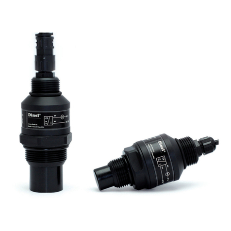
Dinel
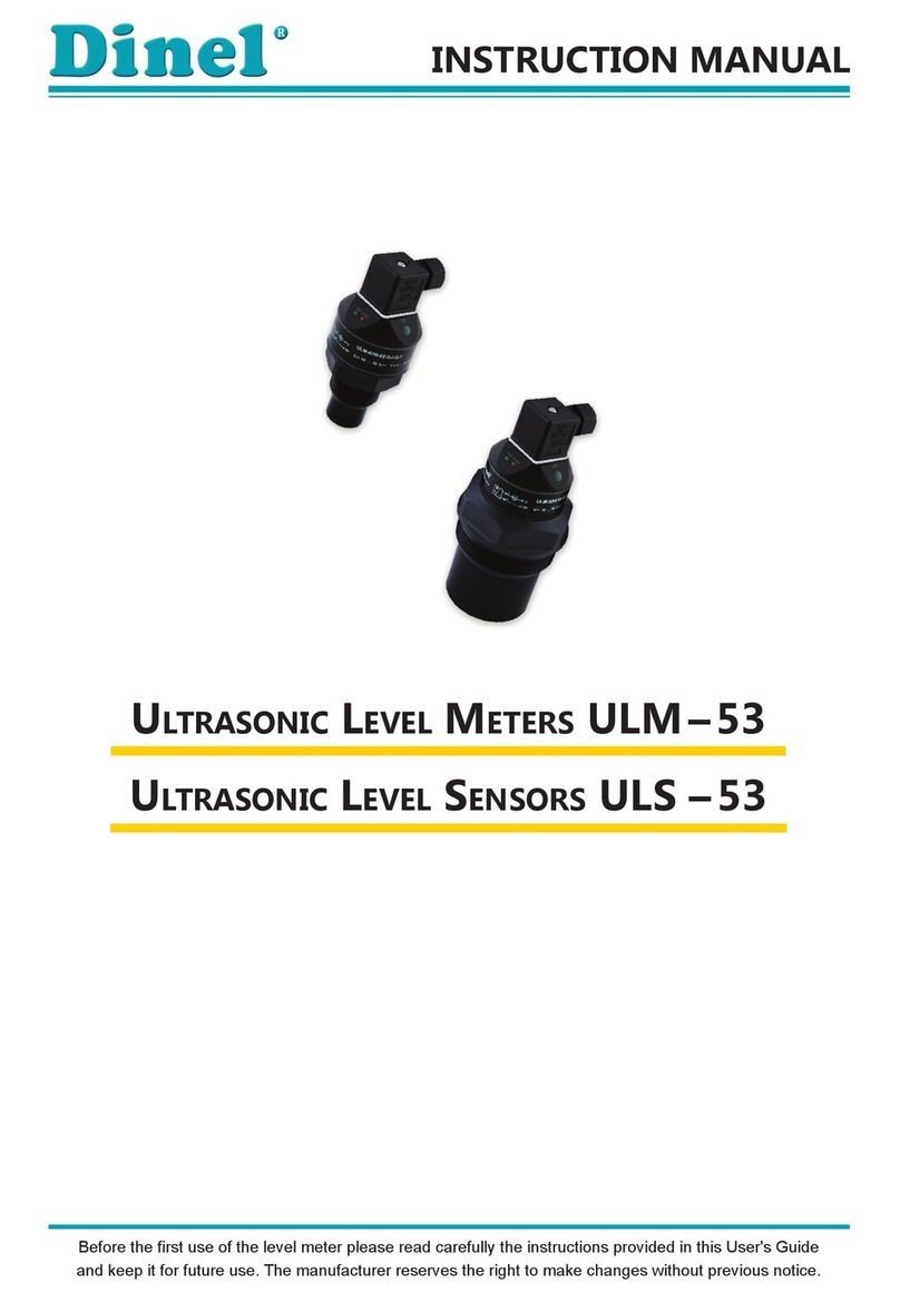
Dinel ULM-53 series User manual

Dinel
Dinel MLM-35 User manual
Dinel
Dinel CLM-36-10 User manual
Dinel
Dinel CLM-36 User manual
Dinel
Dinel ULM-55N User manual
Dinel
Dinel ULM-70 Series User manual

Dinel
Dinel CLM-36 User manual

Dinel
Dinel ULM -70 Series User manual

Dinel
Dinel ULM -70 Series User manual
Dinel
Dinel GRLM-70 User manual
Dinel
Dinel ULM - 54 User manual

Dinel
Dinel ULM-53 series User manual
Dinel
Dinel ULM-53 series User manual
Dinel
Dinel CLM-70 User manual
Dinel
Dinel DLM-35 User manual

Dinel
Dinel ULM-53 series User manual

Dinel
Dinel ULM-53 series User manual

Dinel
Dinel CLM-36 User manual
Dinel
Dinel PDU-40-W Series User manual


