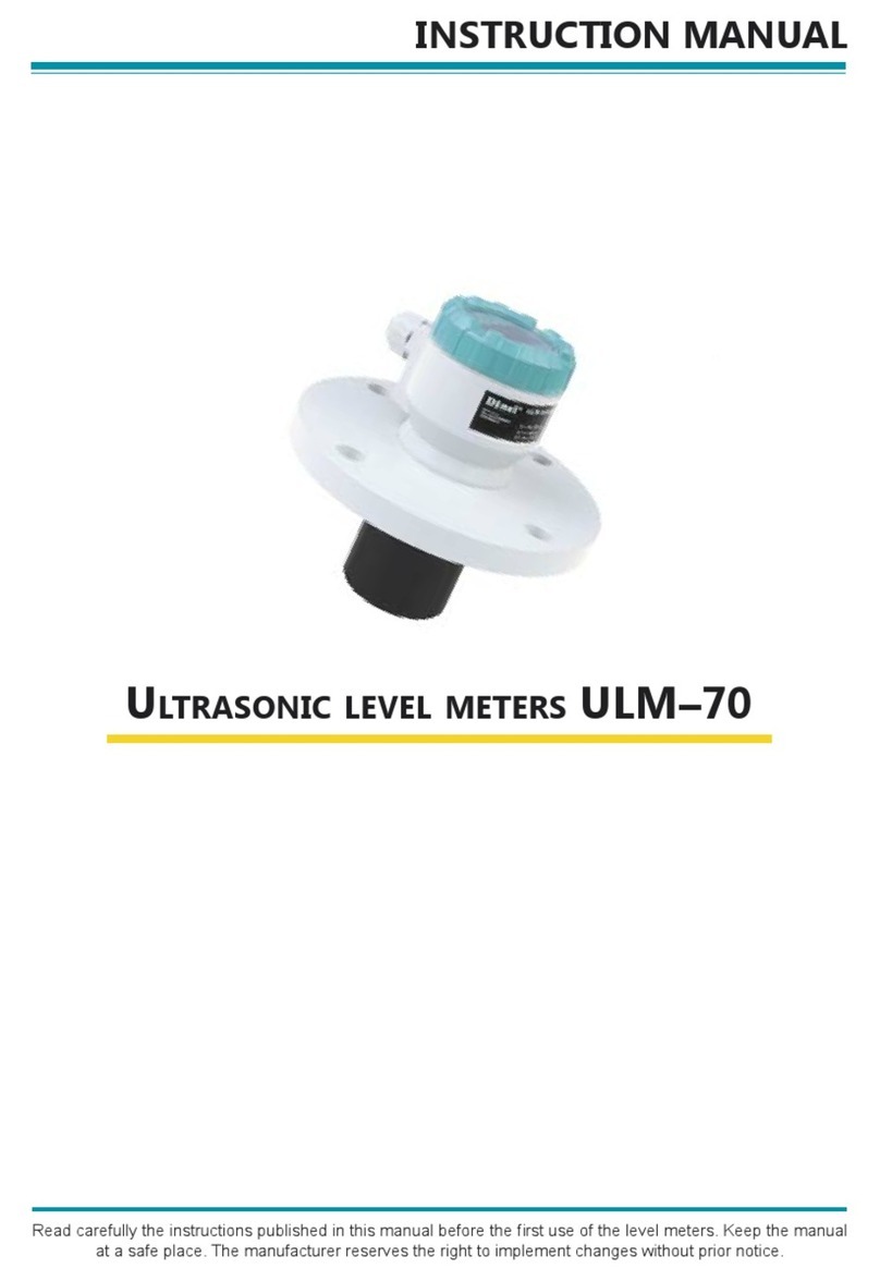
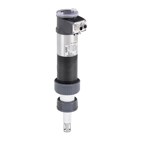
Dinel ULM -70 Series User manual

ULTRASONIC LEVEL METERS ULM–70
ULM-70-dat-1.6
• For continuous non-contact level measurement
• Suited to level measurement of various liquid
and bulk-solid materials
• Outstanding contrast OLED display
• Easy adjustment without measured material
• Quick view measured values on the display
• Xi version for usage in explosive areas
• Current output (4 ... 20 mA) with HART
communication protocol
• ULM–70_–02–I Measuring range from 0.15 m to 2 m, plastic PVDF transmitter, mechanical connection with
thread G 1".
• ULM–70_–06–I Measuring range from 0.25 m to 6 m, plastic PVDF transmitter, mechanical connection with
thread G 1 ½".
• ULM–70_–10–I Measuring range from 0.4 m to 10 m, plastic PVDF transmitter, mechanical connection with
HDPE polyethylene flange (version "N") or aluminium alloy flange (version "Xi").
• ULM–70_–20–I Measuring range from 0.5 m to 20 m, plastic PVDF transmitter, mechanical connection with
aluminium alloy flange.
FEATURES OF VARIANTS
The ULM®ultrasonic level meters are compact measurement devices including an electroacoustics converter, central proces-
sor unit and display module. Using the electroacoustics converter, the level meters transmit the sequence of ultrasonic pulses
that spread towards the surface level. The converter recuperates reflected acoustic waves that are subsequently processed in
the electronic module. The intelligent evaluation block filters out interfering signals, compares the cleaned received signal with
the false reflection map (e.g. from mixers, ladders, reinforcement etc.) and selects a suitable reflection (echo). Based on the
period during which the individual pulses spread towards the surface level and back and based on the measured temperature
in the tank, the instant distance to the surface level is calculated. According to the level height, the level meter output is set and
the measured value is displayed on the display.
The level meters are suited to level measurement of various liquid materials, sewerage waters, mash and paste materials, sus-
pensions in closed or open vessels, sumps, reservoirs and open channels. In case the level of bulk-solid materials is measured,
the measurement range is reduced. We recommend to consult the use with the manufacturer.

ULM-70-dat-2.6
DIMENSIONAL DRAWINGS
ULM – 70_– 02–I ULM – 70_– 06–I
ULM–70N–10–I
ULM–70_–20–I
ULM–70Xi–10–I
Al alloy
Al alloy
HDPE
Pg11 cable gland
ground terminal

ULM-70-dat-3.6
TECHNICAL SPECIFICATIONS
Measuring range 1)
ULM–70_–02–I
ULM–70_–06–I
ULM–70_–10–I
ULM–70_–20–I
0.2 ... 2 m
0.25 ... 6 m
0.4 ... 10 m
0.5 ... 20 m
Supply voltage ULM–70N–__–I
ULM–70Xi–__–I
18 ... 36 V DC
18 ... 30 V DC
Output 4 ... 20 mA (limit value 3.9 ... 20.5 mA), HART
Resolution < 1 mm
Accuracy (within the total range) 0,15%
Temperature error max. 0.04% / K
Beamwidth (-3 dB)
ULM–70_–02;10–I
ULM–70_–06–I
ULM–70_–20–I
10°
14°
12°
Ambient temperature range ULM–70_–02;06–I
ULM–70_–10;20–I
-30 ... +70°C
-30 ... +60°C
Short-time temperature stress resistance +90°C / 1 hour
Max. operation overpressure (on transmission surface) 0.1 MPa
Sensitivity 3 steps (low – medium – high)
Damping 0 ... 99 sec.
Measuring period 1 ... 4 sec.
Delay between supply power rise time and first measurement 30 sec.
Additional technical data 2) (only for variant Xi) – Max. internal values
Ui=30V DC; Ii=132mA; Pi=0.99W; Ci=370nF; Li=0.9mH
Failure indication (echo loss, level in dead zone, internal failure) Adjustable in modes:
3.75mA ; 22mA ; last measured value
Protection class IP67
Mechanical connection
ULM–70_–02–I
ULM–70_–06–I
ULM–70N–10–I
ULM–70Xi–10–I
ULM–70_–20–I
screwing with thread G 1''
screwing with thread G 1½''
HDPE flange
aluminium alloy flange
aluminium alloy flange
Recommended cable PVC 2 x 0.75 mm2 (3 x 0.5 mm2)
Current output load resistance (U = 24 V DC) Rmax = 270 Ω3)
Weight
ULM–70_–02–I
ULM–70_–06–I
ULM–70N–10–I
ULM–70Xi–10–I
ULM–70_–20–I
0.3 kg
0.4 kg
0.7 kg
1.2 kg
3.1 kg
1) In case the level of bulk-solid materials is measured, the measurement range is reduced.
2) Allowed temp. range in the zone 0: -20°C ... +60°C, Allowed press. range in the zone 0: 80 ... 110 kPa.
3) Including 250R resistor in case of HART connection.
AREA CLASSIFICATION (according to EN 60079-10 and EN 60079-14)
ULM–70N–_ _–I Performance for non-explosive areas
ULM–70Xi–02–I
ULM–70Xi–06–I
Explosive proof – suitable for explosive areas (combustible gases or vapours)
II 1/2G Ex ia IIB T5 with isolating repeater (IRU–420)
the whole level meter – zone 1, front head part – zone 0
ULM–70Xi–10–I
Explosive proof – suitable for explosive areas (combustible gases or vapours)
II 1/2G Ex ia IIB T5 with isolating repeater (IRU–420)
the whole level meter – zone 1, front head part – zone 0
ULM–70Xi–20–I
Explosive proof – suitable for explosive areas (combustible gases or vapours)
II 2G Ex ia IIA T5 with isolating repeater (IRU–420)
the whole level meter – zone 1

ULM-70-dat-4.6
INSTALLATION
Level meter is installed into the upper lid of the tank (vessel), using a fixing nut or a flange.
If installed in an open channel (sumps, reservoirs, etc.), install the level meter as closest as you can to the maximum level
expected.
The front of the level meter must be vertically to the measured level.
Foam on the level absorbs the acoustic wave reflection which might cause malfunction of the level meter. If possible select the
location where the foaming is as low as possible.
Protect the level meter against direct sunlight.
In the case of uncertainty we recommend to consult the application with the producer.
Connection diagram of the level meter Internal view of terminal block
The ultrasonic level meter is designed to be connected to supply unit or to
controller through a cable with the outer diameter of 6 ÷ 8mm (recommended
cross-section of cores 0.5-
0.75mm2) by meansof bolted
clips placed under display
module. Connect the plus
pole (+U) to the terminal "+",
the minus pole to 0V to the
terminal "-" and the shielding
to the terminal " " (only for
shielded cables).
ELECTRICAL CONNECTION
Metal clip
Display unit
connector
Terminal
block
m - dead zone
MOUNTING RECOMMENDATION
a - neck height
b - neck width
m - dead zone
Possible installation through the neckRecommended installation
c - measuring range
d - min. distance from tank wall
Maximum level distance from ULM
Installation distance from the tank wall
ULM–70_–02; 10–I d > 1/12 c
(min. 200 mm)
ULM–70_–06–I d > 1/8 c
(min. 200 mm)
ULM–70_–20–I d > 1/10 c
(min. 200 mm)
ULM–70_–02; 06–I a < 3 b
b > 100 mm
ULM–70_–10–I a < 1,5 b
b > 100 mm
ULM–70_–20–I a < 1,5 b
b > 150 mm

ULM-70-dat-5.6
RANGE OF APPLICATIONS
For continuous non-contact level measurement of liquids (water solutions, sewerage water, etc.), mash and paste materials (sedi-
ments, sticks, resins etc.) in closed or open vessels, sumps, reservoirs and open channels. In case the level of bulk-solid materials
is measured, the measurement range is reduced. We recommend to consult the use with the manufacturer.
button
– Set-up mode access
– Confirmation of selected item in the menu
– Saving of set-up data
button
– Move in the menu
– Change of values
button
– Cancelling of carried out changes
– Shift one level up
LEVEL METER SETTING
Set the level meter using 3 buttons placed on the display module. All settings are accessible in the ULM-70 set-up mode access.
For detailed information please read at the instructions manual.
* Slow flashing while the reflected signal (echo) is received from the measured level.
Units
Teaching
mode activation Echo receiving *
Display
of measured values
Set-up elements
CORRECT SPECIFICATION EXAMPLES
ULM–70N–02–I ULM–70N–10–I
ULM–70Xi–06–I ULM–70Xi–20–I
With regard to possible occurrence of electrostatic charge on non-conductive parts of the level meter for explosive areas (Xi ver-
sion) must be grounded with ground terminal!
The power supply can be a stabilized voltage supply unit of 18 ÷ 36V DC (30V DC for Xi version) that is included in evaluation or
display unit.
In case of strong electromagnetic interference (EMI), parallel supply cable with power lines, or when the cable length exceeds
30m, we recommend you to use a shielded cable.
Always disconnect the supply voltage before connecting the level meter!
ORDER CODE
Performance:
Maximum range: 02 - 0.2 ... 2 m
06 -0.25 ... 6 m
10 -0.4 ... 10 m
20 -0.5 ... 20 m
ULM – 70 –
N- Normal - usable in non-explosive areas only
Xi - Explosion proof - suitable for explosive areas
–
Output type: I- current

Dinel, s.r.o.
U Tescomy 249
760 01 Zlín, Czech Republic
Phone:
Fax:
+420 577 002 003
+420 577 002 007
www.dinel.cz
version 01/2010
ULM-70-dat-6.6
ACCESSORIES
Standard – included in the price of the level meter Optional – for extra charge
• 1x Seal (only for ULM–70_–02–I, 06–I) • Stainless fixing nut UM–G1'' (for ULM–70_–02–I)
• Stainless fixing nut UM–G1 ½'' (for ULM–70_–06–I)
SAFETY, PROTECTION, COMPATIBILITY AND EXPLOSION PROOF
The level meter ULM–70 is equipped with protection against reverse polarity and output current overload.
Protection against dangerous contact is secured by low safety voltage that complies with EN 33 2000-4-41.
Electromagnetic compatibility according to EN 55022/B, EN 61326/Z1 and EN 61000-4-2 to 6.
Explosion proof of ULM–70Xi type complies with the following standards: EN 60079-0 : 2007; EN 60079-11 : 2007 ;
EN 60079-26 : 2007 and examined by FTZÚ-AO 210 Ostrava - Radvanice certificate No.: FTZÚ 09 ATEX 0277X.
ULM a Dinel are registered trademark of company Dinel s.r.o.
This project was realised under financial support from the funds of the state budget through the
"Department of Trade and Industry".
Other manuals for ULM -70 Series
1
This manual suits for next models
4
Table of contents
Other Dinel Measuring Instrument manuals
Dinel
Dinel CLM-70 User manual
Dinel
Dinel ULM - 54 User manual

Dinel
Dinel ULM-53L User manual
Dinel
Dinel ULM-53 series User manual
Dinel
Dinel CLM-36 User manual
Dinel
Dinel ULM-53 series User manual
Dinel
Dinel ULM-55N User manual

Dinel
Dinel ULM-53 series User manual

Dinel
Dinel ULM-53 series User manual

Dinel
Dinel CLM-36 User manual
