Dinel GRLM-70 User manual

Read carefully the instructions published in this manual before the rst use of the level meter. Keep the manual
at a safe place. The manufacturer reserves the right to implement changes without prior notice.
GRLM–70


1 . Basic description ..................................................................................................................... 4
2 . Range of application ................................................................................................................ 4
3 . Variants of sensors .................................................................................................................. 5
4 . Dimensional drawings ............................................................................................................. 6
5 . Installation and putting into operation ...................................................................................... 8
6 . Mechanical mounting ................................................................................................................ 9
7 . The installation of the custom measuring electrode,exchange or shortening of the electrode ...19
8 . Electrical connection ............................................................................................................... 23
9. GRLM-70 connection examples ............................................................................................. 25
9.1. Connection diagram of the level meter with current output to the UHC-01 converter . 25
9.2. Connection diagram of the level meter with the Modbus output to the URC-485 unit . 27
9.3. Connection diagram of the level meter with the current output to the PCU unit .......... 28
9.4. Connection diagram of the level meter with the current output to the PDU unit .......... 29
9.5. Connection diagram of the level meter with the current output to the MGU unit ......... 29
9.6. Connection diagram of the level meter with the MODBUS output
to the MGU unit using RS485 / MODBUS ........................................................................... 29
10 . Setting elements ..................................................................................................................... 31
11 . Settings .................................................................................................................................. 32
11.1. Initial setting procedure during commissioning .......................................................... 32
11.2. Basic settings ............................................................................................................ 33
11.3. Service settings ......................................................................................................... 36
11.4. Additional functions ................................................................................................... 39
12 . HART®protocol ...................................................................................................................... 42
12.1. Parametrization of GRLM-70 using the Hart® protocol with PCU-100-H ................... 43
12.2. Parametrization of GRLM-70 using the Hart®protocol
with the UHC-01 communicator........................................................................................... 43
13 . Protocol Modbus® ................................................................................................................... 44
14 . Function and status indication ............................................................................................... 44
15 . Order code ............................................................................................................................. 45
16 . Accessories ............................................................................................................................ 46
17 . Safety, protection, compatibility and explosion proof ............................................................. 46
18 . Use, manipulation and maintenance ...................................................................................... 47
19 . General conditions and warranty ........................................................................................... 47
20 . Marking of labels .................................................................................................................... 48
21 . Technical specications .......................................................................................................... 50
22. Packing, shipping and storage ............................................................................................... 58
23 . Menu structure ........................................................................................................................ 59
GRLM–70 © Dinel, s.r.o.
4
The GRLM®radar level meters are compact measuring devices consisting of three main parts
- measuring electrodes, housing with the computing electronics (head) and a display module
(screen). The electronic transmits very short electrical pulses (0.5 ns), which is connected with a
one-wire transmission line (measuring electrode). Measuring electrode can be formed from rod or
rope. The pulse propagates along the electrode in the form of electromagnetic wave toward the
level part of electromagnetic wave, where it is partly reected and the reected returned to the
receiving module of the electronic. The electronic measures the time of ight of electromagnetic
wave and the current (actual) distance to the level is calculated. Then based on the height of the
level, the level meter current output 4 ... 20 mA is set with the HART communications or an industrial
RS-485 line with Modbus RTU communications and the measured value is shown on the display.
Radar level meters with guided wave are suited to continuous level measurement of various
liquid, mush and bulk-solid materials. Level meters are resistant against changes in the atmos-
phere (pressure, temperature, dust, steam) and to changes in medium parameters (change in
dielectric constant, conductivity).
To ensure maximum safety of control processes, we have dened the following safety instructions
and information. Each instruction is labelled with the appropriate pictogram.
This symbol informs you about particularly important instructions for installation and operation of
equipment or dangerous situations that may occur during the installation and operation. Not observing
these instructions may cause disturbance, damage or destruction of equipment or may cause injury.
This symbol indicates particularly important characteristics of the device.
This symbol indicates helpful additional information.
Alloperationsdescribedinthis instruction manual have to be carried out by trained personnel
or by an accredited person only. Warranty and post warranty service must be exclusively
carried out by the manufacturer.
Improper use, installation or set-up of the sensor can lead to crashes in the application.
The manufacturer is not responsible for improper use, loss of work caused by either direct
or indirect damage, and for expenses incurred at the time of installation or during the period
of use of the level sensors.

5
© Dinel, s.r.o. GRLM–70
• GRLM–70_–00 Without electrode, the electrode is made by customer (only variant 10
or 30) and connected to the electrode junction by M8 thread.
• GRLM–70_–10 Uncoated stainless steel rod electrode, for level measurement liquids
and bulk solid materials (water solutions, emulsion, oils, diesel, our, sand,
granulates, etc.). Electrode length 0,5 ... 8 m.
• GRLM–70_–11 Fully coated stainless steel rod electrode (PFA), for level measurement
of aggressive liquids and very pure liquids. Electrode length 0,5 ... 2 m.
• GRLM–70_–12 Fully coated stainless steel rod electrode (FEP), for level measurement
of aggressive liquids and drinks. Electrode length 0,5 ... 2 m.
• GRLM–70_–13 Semi-coated stainless steel rod electrode (FEP), for level measure-
ment of liquids in area,where it could condense steam on the electrode.
Electrode length 0,5 ... 8 m.
• GRLM–70_–20 Uncoated stainless steel rod electrode with reference tube (coaxial),
for accurate level measurement of liquids in cramped spaces. Electrode
length 0,5 ... 3 m.
• GRLM–70_–30 Uncoated stainless steel rope electrode and weight, for level
measurement of liquids and bulk solid materials (water, grains, sand, our,
cement, etc.) in higher silos, vessels, reservoirs. Electrode length 1 ... 40 m.
• GRLM–70_–32 Fully coated stainless steel rope electrode (FEP) and coated weight
(PTFE), for level measurement of aggressive liquids and very pure liquids.
Electrode length 1 ... 12 m.
• GRLM–70_–33 Uncoated stainless steel rope electrode with anchorage, for level
measurement of bulk solid materials (grains, our, cement, etc.) It is
recommended to anchor in storage tanks and silos for bulk solid materials
up to a depth of 10 meters. . Electrode length 1 ... 40 m.
• GRLM–70_–34 Coated stainless steel rope electrode (Polyamide) and uncoated
weight, for level measurement of liquids and adhesive bulk solids (our,
cement, etc.). Electrode length 1 ... 40 m.
• GRLM–70_–35 Coated stainless steel rope electrode (Polyamide) with uncoated
anchorage, for level measurement of adhesive bulk solids (our, cement,
etc.). It is recommended to anchor in storage tanks and silos for bulk solid
materials up to a depth of 10 meters. Electrode length 1 ... 40 m.
• GRLM–70_–36 Uncoated rope electrode without weight, for level measurement of
unsticky bulk solids (grains, sand, etc.) Anchoring with rope clamps and
eye ring. Recommended anchoring in storage tanks and silos deeper than
10 meters. Electrode length 1 ... 40 m.
• GRLM–70_–37 Coated rope electrode without weight (rope coated with polyamide),
for level measurement of sticky bulk solids (our, cement, etc.). Anchoring
with cable clamps and eye ring. Recommended anchoring in storage tanks
and silos deeper than 10 meters. Electrode length 1 ... 40 m.
GRLM–70 © Dinel, s.r.o.
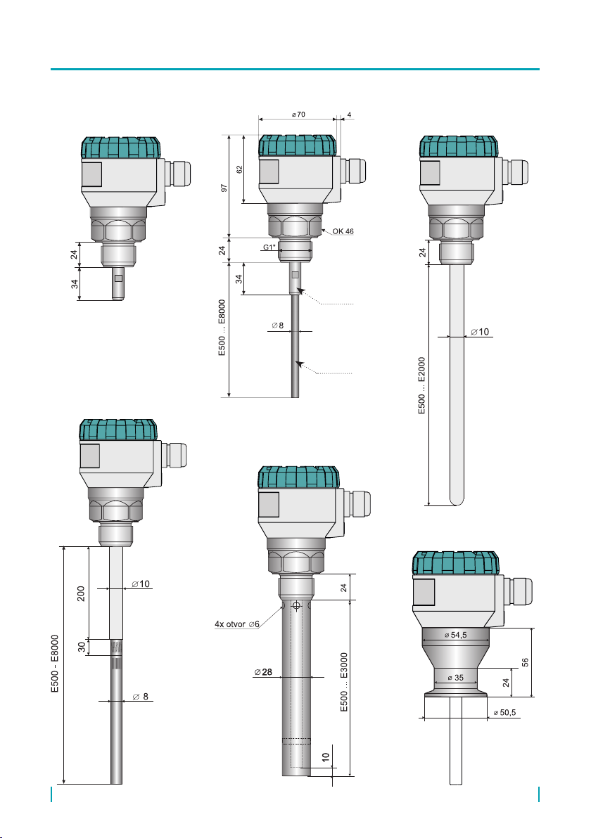
6
GRLM–70_–20
GRLM–70_–00
GRLM–70_–13
Procesní připojení
Tri-clamp
GRLM–70_–10 GRLM–70_–11(12)
holder of
electrode
electrode
7
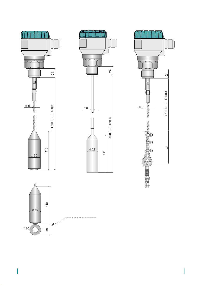
© Dinel, s.r.o. GRLM–70
* Details on rope length, attachment or shortening for version GRLM-70_-36 (37) on pages 22 and 37.
GRLM–70_–30(33,34,35) GRLM–70_–36(37)
*
GRLM–70_–32
Anchoring eye for variant
GRLM-70_-33 (35)
GRLM–70 © Dinel, s.r.o.
8
Please follow next 4 steps:
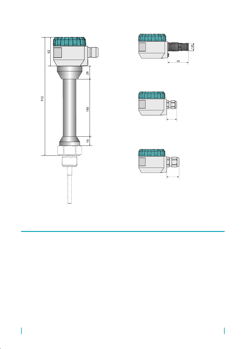
High temperature performance
GRLM–70_T
performance "H1"
cable gland for protective hose M16
performance "B1"
plastic cable gland M16
performance "B2"
plastic cable gland M20
26
28
26
28
9
© Dinel, s.r.o. GRLM–70
• Install the level meter into the upper lid of the tank or reservoir using a welding ange or
fastening nut.
• The min. distance to install the level meter into a lid or a ceiling of a tank from the tank wall or
bottom is given in table below.
• Otherwise, the level meter install as far as possible from the walls, to the middle between the
wall and the vertical inlet, see Fig. 1., 2, 3 and 4.
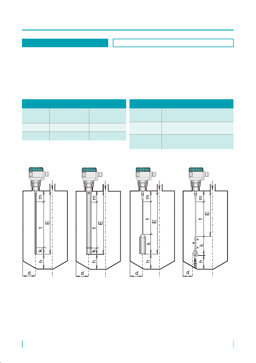
BASIC INFORMATIONS VALID FOR: all types
E – The length electrode
t – Maximum measuring range
m – Dead zone on the beginning of electrode
k – Dead zone on the end of electrode or the length of
weight (110 mm) at the rope
d – The distance from the tank wall (see. Tab. above)
h – The distance from the bottom (see. Tab. above)
type of
wall
d
(without ref. tube)
d
(with ref. tube)
metal ≥ 300 mm*any distance
non-metal ≥ 500 mm* any distance
* it is recommended that a smaller distance from a wall is consulted
with the manufacturer.
type of
electrode h
rod
(no anchoring)
≥ 100 mm2) (length of electrode to 2 m)
≥ 150 mm2) (length of electrode over 2 m)
rope
(no anchoring)
≥ 100 mm (length of electrode to 10 000 mm)
≥ 150 mm (length of electrode over 10 000 mm)
2) In case of a sloping bottom the distance "h" should be twice as long.
Fig. 1: Level meter
installation with the
rod electrode
Fig. 3: Level meter
installation with the rope
electrode
Fig. 4: Level meter
installation with the rope
electrode without weight
Fig. 2: Level meter
installation with the
reference tube

GRLM–70 © Dinel, s.r.o.
10
• It is an area in which continuous level measurement takes place. The maximum measur-
ing range is determined by the length of the measuring electrode with the subtraction of
dead zones at the beginning and at the end of the electrode, see Figs. 1, 2, 3, and 4. This
range is also the default setting of the level meter. The maximum measuring range can be
reduced by the user by changing the minimum and maximum levels in case of obstacles
near the end or in particular at the beginning of the measuring electrode.
• If the measured level falls out of the measuring range limits, the level meter will enter the failure
mode and the output current will resume the value that was set by the user, see service settings
– Failure Mode, p. 38 (the default value for the failure mode is provided in the Default Settings
Table, p. 57). For the M Modbus version, the corresponding bits of the measurement status
register 104 are activated, see the Variables Table for GRLM-70 Modbus.
MEASURING RANGE VALID FOR: all types
• In connection with the measurement principle, electromagnetic waves reected in the area im-
mediately below the level meter and also at the end of the electrode cannot be evaluated (see
Figs. 1, 2, 3, and 4). These zones determine either the minimum possible distance between
the level meter and the highest level (“m” parameter) or the minimum distance at the end of the
electrode (“k” parameter). The level meter must be installed in such a way that the level
does not interfere with the dead zones at the maximum and minimum possible lling of
the storage tank.
• The size of the dead zone is shown in Figs. 49–52 on pages 51, 52.
DEAD ZONE VALID FOR: all types
• For correct measurement, it is im-
portant to avoid installing the level
meter in a high input neck or high
welding ange. If this is not possible,
the level meter may be installed in
a short input neck, the parameters
of which are provided in g. 5. Here
it applies that the neck diameter se-
lected should be as large as possi-
ble but the neck height should be as
small as possible.
Fig. 5: Level meter installation
in the input neck
a ≤ b
b ≥ 50 mm
a – neck height
b – neck width
INPUT NECK VALID FOR: all types except GRLM-70_-20
When installing the level meter
into an input neck, use the
TEACHING procedure (see
chapter11.2. Basic settings). This
will put the sensor into a mode
that suppresses false reections.
• The end of the socket or the welding
ange must not have an extension
into the tank in Fig. 6.
• Dimension restrictions of the input
nozzle does not apply to the use of
GRLM-70_-20 with reference tube.
Fig. 6: Incorrect welding ange
mounting to the tank

11
© Dinel, s.r.o. GRLM–70
• When installing the level meter into the roof of a concrete silo, the level meter installation hole
b must be larger than the thickness of the concrete a, see g. 8.
• In the event that the thickness of the concrete is greater than the diameter of the hole, it is
necessary to install the level meter into a countersink, see g. 9.
a < b
• To install the level meter in a non-
metallic water tank, it is necessary
to insert a metal plate with a diame-
ter greater than 200 mm in the area
of the process connection, see g.
7. The metal plate must be in con-
tact with the thread stop of the level
meter.
Fig. 7: Level meter installation
in the non-metal tank
Fig. 8: Level meter installation
on the roof of the concrete silo
Fig. 9: Level meter installation
on the roof of the concrete silo
NON-METAL TANK VALID FOR: all types except GRLM-70_-20
CONCRETE SILO VALID FOR: GRLM-70_-30, 32, 33, 34, 35, 36, 37
• The level meter must not be installed
in locations exposed to direct solar
radiation and must be protected
against the eects of weather.
In the event that installation in a
location with direct solar radiation
is unavoidable, it is necessary to
install a shielding cover above the
level meter (g. 10).
Fig. 10: Solar radiation shielding cover
LEVEL METER PROTECTION VALID FOR: all types
GRLM–70 © Dinel, s.r.o.
12
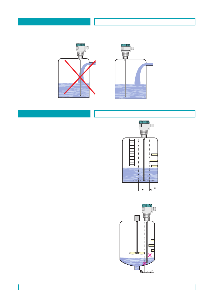
• It is not recommend to install the level meter in or above the lling location. Measurement may
be aected by the medium owing in rather than measuring the level of the material.
s - Radius of protective
zone along the electrode
level meter
s = 300 mm
• The level meter generates electro-
magnetic guided wave, which cre-
ates an electromagnetic eld along
the electrode. Objects placed close
to the electrode disturb the elec-
tromagnetic eld and thus aect
the measurement. Therefore, it is
determined protective zone along
the electrode of radius 300 mm.
The level meter is recommended
to install the tank so that the items
placed inside the tank (ladders,
various partitions, mixers, etc.)
does not intervene into the protec-
tive zone, see Fig. 12.
Fig. 11: Level meter installation outside the inuence of lling
Fig. 12: Level meter installation
outside obstacles in the tank
OUTSIDE THE INFLUENCE OF FILLING VALID FOR: all types
OBSTACLES IN THE TANK VALID FOR: all types except GRLM-70_-20
• If still these objects intervene into
the protective zone of the level me-
ter, it is necessary to create a map
of false reections by activating the
"TEACHING" mode (p. 35). In case
of installed mixers, it is necessary
to position the mixers near the level
meter (turning the mixer blade to the
proximity of the electrode). Items
inside the tank must not be from
the electrode distance of less than
100 mm, because a interference of
electromagnetic eld is very strong
in this zone and "TEACHING" mode
can not be used.
n = 100 mm
Fig. 13: Incorrect level meter
installation close to obstacles
n - minimal distance of
objects from the elec-
trode from level meter

13
© Dinel, s.r.o. GRLM–70
• For the type of level meter with
reference tube (coaxial) electro-
magnetic guided wave propagates
inside the reference tube. This
wave is not aected by the ambient
environment. So for this type of ra-
dar is not intended protective zone
around the electrodes and the level
meter can be used for measure-
ments in cramped spaces.
Fig. 15: Level meter installation with
reference tube (coaxial) in cramped spaces
CRAMPED SPACES VALID FOR: GRLM-70_-20
• When measuring the level of ag-
gressive media (strong acids, lyes,
chlorides, hydrogen chloride, etc.) in
non-conductive vessels.
• The level meter with a rod electrode
is inserted into a non-conductive
tube with a diameter of 16 ... 30 mm.
The tube must have an encapsu-
lated bottom and the upper part is
welded to the non-conductive ceil-
ing of the vessel.
• The level of the medium is meas-
ured through the wall of the non-
conductive tube by a radar. The
value of relative permittivity must
not exceed 3.
• The instructions for mounting the
level meter into a non-metallic ves-
sel apply here, i.e. a metal plate with
the diameter greater than 200 mm
must be inserted at the process con-
nection point.
Fig. 14: Level meter installation with
reference tube (coaxial) into the auxiliary tube
AGGRESSIVE MEDIA VALID FOR: GRLM-70_-10
material: metal
min. Ø 200 mm
material: PE, PP
(εr max=3)
Ø 16 - 30 mm
Ø 12 - 15 mm

GRLM–70 © Dinel, s.r.o.
14
• Type of level meter without electrode
is supplied without an electrode. It is
therefore necessary to a customer
to mount his own made measuring
electrode. The diameter of the elec-
trode must be between 8-10 mm.
For a connection it is necessary that
on the electrode is made M8 thread.
The connection procedure is given
in Sec. 12 page. 30.
Fig. 17: Level meter without electrode
• Deposits, layers and sediments on the electrode may distort measurement and reduce the
permeability of the electromagnetic wave propagated along the electrode.
For the type of level GRLM-
70_-00 manufacturer is not
responsible for failures related
to the mounted measuring
electrode.
DEPOSITS ON THE ELECTRODE VALID FOR: all types
VARIANT WITHOUT ELECTRODE VALID FOR: GRLM-70_-00
• It is appropriate to lead the ca-
ble underneath the cable terminal
(through the dip diagonally down-
wards) This will prevent potential
"ingression of moisture through the
cable grommet. Thereby, rain and
condensing water can ow away
freely, g. 16.
• The cable bushing and connector
have to be suciently tightened to
prevent penetration of humidity.
Fig. 16: Prevention to avoid intrusion of humidity
through cable gland
HUMIDITY VALID FOR: all types

15
© Dinel, s.r.o. GRLM–70
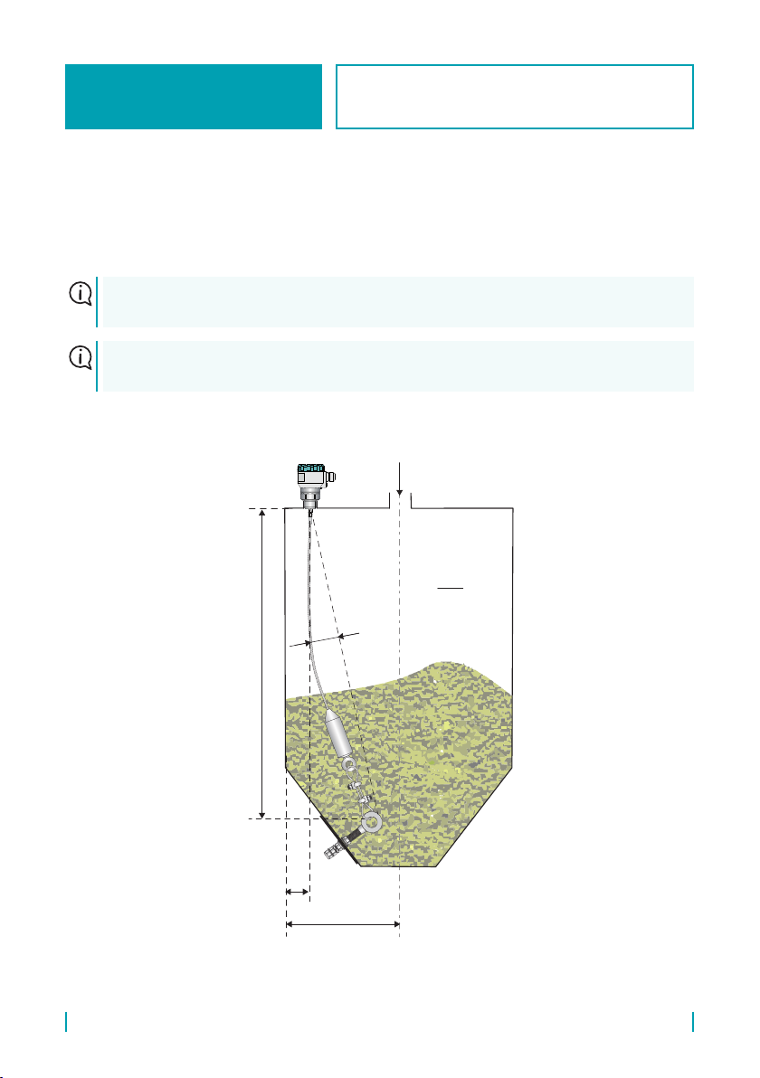
• When calculating the length of the
rope electrode, it is necessary to
take into account that the meas-
urement takes place only up to the
upper edge of the weight, i.e. it is
advisable to choose the electrode
length so that the whole weight is
below the minimum measured level,
see Fig. 18. For variants 30 and
34, it is possible to shorten the
rope electrode.
• The distance the electrode from
the tank wall must be at least 300
mm. Otherwise, the level meter
install as far as possible from the
walls, to the middle between the
wall and the vertical inlet, see Fig.
18. It must be ensured that the rope
electrode could not touch the ves-
sel wall caused by the motion of
the medium. In the case of an unan-
chored rope electrode, its end must
not extend into the conical part of
the storage tank.
• Ensure that the maximum tensile
load on the rope of the electrode is
not exceeded. Its value is specied
in chapter "Technical parameters".
A large load could result in the rope
tearing. The tensile load depends
on the height and shape of the tank,
the thickness and adhesion of the
measured medium and the tank
emptying speed.
E – The length of rope electrode
t – Measuring range
m – Dead zone at the beginning of the electrode
k – The lengt of weight (110 mm)
d – The distance from the tank wall min. 300 mm
h – The distance from the bottom (see. Tab. page 8)
E = m + t + z
Fig. 18: Level meter installation
with the rope electrode
For the electrode shortening procedure, see chapter 7. How to install a custom measuring
electrode, replace or shorten the electrode.
In the case of shortening the electrode, after installation it is necessary to carry out settings in
the MENU of the ELECTRODE option (see p. 36).
ROPE ELECTRODE
WITHOUT ANCHORING
VALID FOR: GRLM-70_-30, 32, 34
GRLM–70 © Dinel, s.r.o.
16
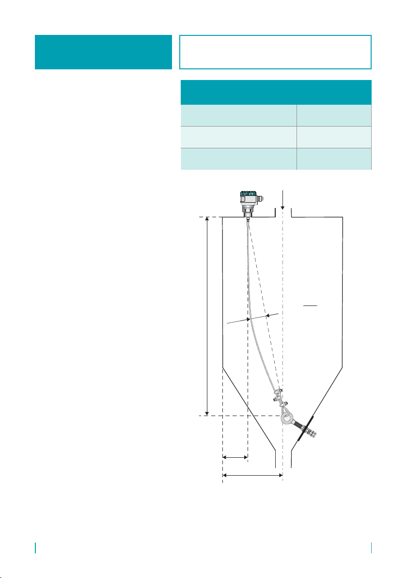
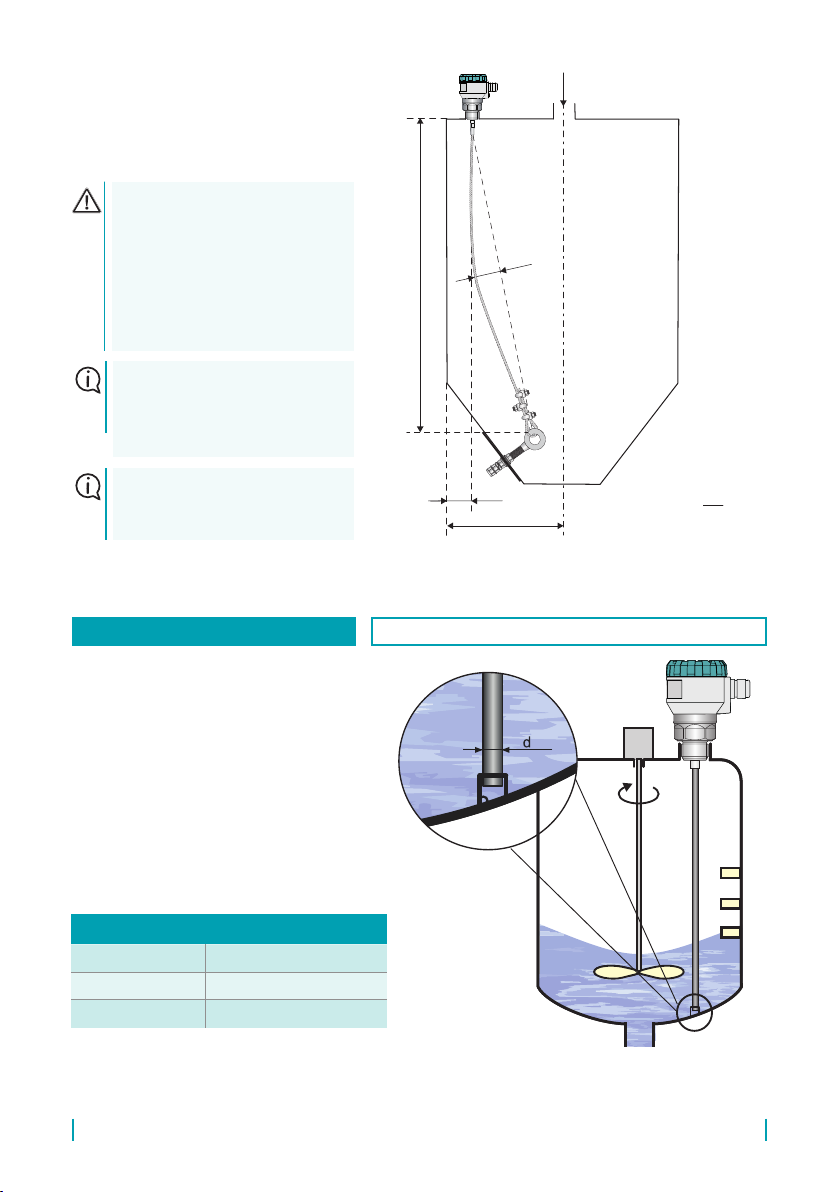
ANCHORING OF THE ROPE
ELECTRODE WITH WEIGHT AND
ANCHORING RING
VALID FOR: GRLM-70_-33, 35
• At the bottom of the tank (silo), it is necessary to install an anchoring point (by welding or drill-
ing an anchoring ring), to connect to the ring at the end of the electrode.
• This anchoring is recommended for applications with liquids, where turbulences occur or
media is stirred, or for applications with bulk solids in small and medium sized silos (up to 10
m height).
For the electrode shortening procedure, see chapter 7. How to install a custom measuring
electrode, replace or shorten the electrode.
In the case of shortening the electrode, after installation it is necessary to carry out settings in
the MENU of the ELECTRODE option (see p. 36).
Obr. 19: Recommended Level meter
installation with anchorage
d
r
p
H
mm 200 50h
E
3
2
m
E
4
3
p
E
3
4
s
E
3
1
E
10
1
a
20
E
40 b
20
H
000 1 r
50
H
000 1 d
100
H
p
mm
mm
mm
d=1000+H/50
17
© Dinel, s.r.o. GRLM–70
• For the variants 36 and 37, an ad-
ditional 1 m of stainless steel rope
length is supplied with a corre-
sponding number of clamps and eye
rings.
• This additional 1 m of stainless steel
rope is intended as a reserve for
pulling through the anchoring eye.
Not intended for level measure-
ment! It comes with three clamps
and one eye ring.
• At the bottom of the tank (silo), it
is necessary to install an anchor-
ing point (by welding or drilling an
anchoring ring), to pull the rope
through and then attached with at
least 2 clamps (3 clamps are rec-
ommended for deep silos over 20
m). When designing the length of
the rope “E”, it is necessary to take
into account the bending of the rope,
or anchoring on the opposite side of
the silo.
• Suitable for bulk media in silos
deeper than 10 meters.
• For applications with bulk solids
it is appropriate to anchor the rope
electrodes at the opposite sides of
the tank (silo) so that the rope is
sagging, see Fig.20. Minimum rec-
ommended sag is p = H/100 [mm].
This installation increases the re-
sistance of the rope to tension load.
d
r
p
H
mm 200 50h
E
3
2
m
E
4
3
p
E
3
4
s
E
3
1
E
10
1
a
20
E
40 b
20
H
000 1 r
50
H
000 1 d
100
H
p
mm
mm
mm
Fig. 20: Recommended installation of the level meter
with anchoring on the opposite side of the silo
Anchoring method r
[mm]
opposite side of the silo (Fig. 20) any
same side of silo (Fig. 21) ≥ 1000 + H/20
H – depth of the silo (from rope start to anchor)
p – rope sag (see formula above)
r – radius of the silo
d – distance to wall (see formula above)
ANCHORING OF THE ROPE
ELECTRODE WITHOUT WEIGHT,
ANCHORED WITH CLAMPS
VALID FOR: GRLM-70_-36, 37
GRLM–70 © Dinel, s.r.o.
18
d
r
p
H
mm 200 50h
E
3
2
m
E
4
3
p
E
3
4
s
E
3
1
E
10
1
a
20
E
40 b
20
H
000 1 r
50
H
000 1 d
100
H
p
mm
mm
mm
Fig. 21: Recommended installation of the level meter
with anchoring on the same side of the silo
After installing the rope using
clampss, a check of the min.
distance of the rope from the
wall (d) and also the bend of
the rope (p) is performed. Then
the rest of the rope must be cut
in close proximity to the last
clamp, see chapter 7.
After installation, it is neces-
sary to carry out settings in the
MENU of the ELECTRODE
option (see p. 36).
A mounting kit for rope anchor-
ing and a rope tensioner are
available as accessories.
• If the ratio of silo width to depth is
determined by formula: r ≥ 1000 +
H/20 [mm], the rope can be anchored
also on the same side of the silo, see
Fig.21.
• Recommended for rod electrodes long-
er than 3 m.
• The end of the measuring electrode
may be installed in a short tube welded
to the bottom of the tank. At the bottom
part of the anchoring tube, it is recom-
mended to have a media overow hole.
The diameter of the tube should ensure
permanent contact of the tube walls
with the electrode.
electrode type d
uncoated 8 mm
fully coated 10 mm
ANCHORING OF THE ROD ELECTRODE VALID FOR: GRLM-70_-10, 11, 12, 13
Fig. 22: Recommended installation
of the level meter with anchoring
of the rod electrode

19
© Dinel, s.r.o. GRLM–70
1. Create your own electrode as shown on Fig. 23 or 24 The length of the electrode must be about
7 mm shorter than the dimension "E" in gure 23. The material of the electrode is recommended
to be used stainless steel type 1.4404 (AISI 316 L) or similar depending on the application.
2. Apply glue intended for securing threaded junctions (the amount of adhesive is determined by
its manufacturer) on to the thread of the prepared electrode produced according to drawing
(see pic. 23 or 24). The glue used must meet certain criteria depending on the application, e.g.
resistance against high temperatures, corrosion, chemicals or must have a permit, e.g. for use
in food processing.
3. Screw the electrode using suitable pliers or a spanner (on the side of the electrode) and a at
spanner 10 mm (on the side of the electrode holder) rmly into the electrode holder.
4. Let the glued junction to harden, as recommended by the glue manufacturer, then the level
meter is ready for installation.
5. After an installation into an empty tank, set a new level meter electrode type and the length -
see Chap. ELECTRODE on the page 36
6. If necessary, enter a new range of level measurement - see Chap. MIN / MAX LEVEL on the
page 33.
Fig. 23: Detail of a drawing of a rod electrode
Fig. 24: Detail of a drawing of a rope electrode
"E" - 55 mm
30
5
Ø
M8
grooves

GRLM–70 © Dinel, s.r.o.
20
24E
Fig. 25: Drawing of a level
meter with a rod electrode
electrode
holder
rod
electrode
60
110
E24
Fig. 26: Drawing of a level
meter with a rope electrode
electrode
holder
rope
electrode
Table of contents
Other Dinel Measuring Instrument manuals

Dinel
Dinel ULM - 54 User manual

Dinel
Dinel ULM-53 series User manual

Dinel
Dinel MLM-35 User manual

Dinel
Dinel DLM-35 User manual

Dinel
Dinel ULM -70 Series User manual

Dinel
Dinel ULM-53 series User manual

Dinel
Dinel ULM-53L User manual

Dinel
Dinel ULM-55N User manual

Dinel
Dinel ULM-53 series User manual

Dinel
Dinel ULM-53 series User manual


Popular Measuring Instrument manuals by other brands


RKI Instruments
RKI Instruments GX-6000 Operator's manual

Waycon
Waycon LLD-150-PROF2 manual

Endress+Hauser
Endress+Hauser Deltabar FMD71 technical information

Teledyne Lecroy
Teledyne Lecroy WaveMaster 8000HD Getting started guide

BioLAB
BioLAB BSFL-103 Operation manual

Zoom
Zoom H1essential Firmware update guide