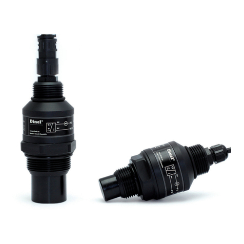
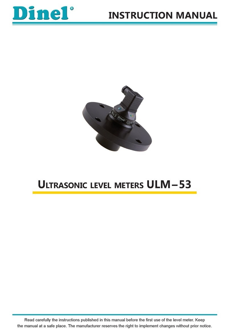
Dinel ULM-53 series User manual

Read carefully the instructions published in this manual before the first use of the level meters. Keep the manual
at a safe place. The manufacturer reserves the right to implement changes without prior notice.
INSTRUCTION MANUAL
ULTRASONIC LEVEL METERS ULM–53


CONTENT
Safety ...............................................................................................................................................3
Measuring principle..........................................................................................................................3
Range of application ........................................................................................................................3
Features of variants .........................................................................................................................3
Dimensional drawings ....................................................................................................................4
Installation instructions ....................................................................................................................5
Electrical connection ......................................................................................................................8
Set-up elements...............................................................................................................................8
Status and failure signalization........................................................................................................9
Operational modes ..........................................................................................................................9
Setting up .........................................................................................................................................9
Order code ..................................................................................................................................... 11
Accessories ....................................................................................................................................11
Safety, protection, compatibility and explosion proof.................................................................... 11
Use, manipulation and maintenance .............................................................................................11
Marking of labels............................................................................................................................12
Technical specifications.................................................................................................................16
Area classification..........................................................................................................................17

ULM–53 © Dinel, s.r.o.
3
SAFETY
All operations described in this instruction manual have to be carried out by trained personnel or by
an accredited person only. Installation, commissioning, operation and maintenance of the ultrasonic
level meters has to be carried out in accordance with this instruction manual; the provisions of
regulations in force regarding the installation of electrical equipment have to be adhered to.
Improper use, installation or set-up of the sensor can lead to crashes in the application, (overfilling
of the tank or damage of system components).
The manufacturer is not responsible for improper use, loss of work caused by either direct or
indirect damage, and for expenses incurred at the time of installation or during the period of use
of the sensor.
Customer service must be carried out by the manufacturer exclusively.
MEASURING PRINCIPLE
The ULM®ultrasonic level meters are compact measurement devices containing an ultrasonic
transmitter and an electronic module. Using an transmitter, level meters transmit the series of
ultrasonic pulses that spread towards the level surface. The transmitter recuperates reflected
acoustic waves that are subsequently processed in the electronic module. Based on the period
during which the individual pulses spread towards the level and back, this period is averaged by
the electronics that performs temperature compensation and subsequently a conversion to an
output current (voltage).
RANGE OF APPLICATION
For continuous non-contact level measurement of liquids (water solutions, sewerage water, etc.),
mash and paste materials (sediments, sticks, resins etc.) in closed or open vessels, sumps, reser-
voirs and open channels. In case the level of bulk-solid materials is measured, the measurement
range is reduced.
All setting-up is done using two buttons positioned in the upper part of the sensor. The level meter
is equipped with optical state indication (STATE) and with a setting-up process (MENU). The level
meter can output current or voltage signals. They are manufactured in model versions for non-
explosive areas (N) and explosive areas (Xi).
ULM–53_–02–_ measuring range from 0.25m to 2m, plastic PVDF transmitter and plastic
body (PP+HDPE), process connection with thread G 1".
ULM–53_–06–_ measuring range from 0.25m to 6m, plastic PVDF transmitter and plastic
body (PP+HDPE), process connection with thread G 1 ½".
ULM–53_–10–_ measuring range from 0.5m to 10m,plastic PVDF transmitter and plastic
body (PP+HDPE), aluminium alloy ("Xi" version) or HDPE ("N" version)
flange.
ULM–53_–20–_ measuring range from 0.5m to 20m, with plastic PVDF transmitter and
plastic body (PP+HDPE), aluminium alloy flange.
FEATURES OF VARIANTS

4
© Dinel, s.r.o. ULM–53
DIMENSIONAL DRAWINGS
ground
terminal
ULM–53_–02–_ ULM–53_–06–_
ULM–53N–10–_
ULM–53_–20–_
ULM–53Xi–10–I
Al alloy
ground
terminal
Al alloy
HDPE

ULM–53 © Dinel, s.r.o.
5
Fig. 2: Level meter dead zone
m – Dead zone
INSTALLATION INSTRUCTIONS
Install the level meter in a• vertical position into the upper lid of the tank (vessel) or reservoir
using a lug, a fastening nut or a flange in such a way that the ULM axis is perpendicular to the
level of the measured liquid (Fig. 1).
M i n i m u m• dimension parameters when installing into
a lid or a ceiling of a tank are listed in Fig. 3.
When installing in an• open channel (reservoir, drain
and the like), install the level meter onto a console to
the expected maximum level as close as possible.
In compliance with the measurement principle, no sig-•
nals reflected in the area directly below the level me-
ter (the so-called dead zone) can be evaluated. The
dead zone (Fig. 2) determines the minimum distance
possible between the level meter and the highest sur-
face level. Medium minimum distance parameters are
listed in chapter on "Technical specifications".
It is necessary to install the level meter in such a way•
that the bin level does not interfere with the dead
zone when filled up to the maximum. If measured level
interferes with the dead zone, the level meter will not
work properly.
Fig. 1: Recommended installation
in the tank
Fig. 4: Possible installation of the installation neck
Fig. 3: Installation distance from the tank wall
d – Distance from tank
wall
c – Measuring range
In case the maximum surface level in the tank interferes with the dead zone, the level meter•
has to be mounted into a higher installation neck. Subsequently, the tank can be filled nearly
up to the maximum volume. The neck's inner surface has to be even and smooth (without
edges and welded joints), the inner edge should be rounded in the position point where the
ultrasonic waves leave the pipe. Choose the largest possible neck's diameter, but keep the
neck's height as low as possible. Recommended dimensions of the neck are listed in Fig. 4.
a– Neck height
b– Neck width
m– Dead zone
ULM–53–02;06 a< 3b
b>100mm
ULM–53–10 a<1,5b
b>100mm
ULM–53–20 a<1,5b
b>150mm
ULM–53–02 ;10 d>1/12c
(min. 200 mm)
ULM–53–06 d>1/8c
(min. 200 mm)
ULM–53–20 d>1/10c
(min. 200 mm)

6
© Dinel, s.r.o. ULM–53
Foam• on the level absorbs the acoustic wave re-
flection which might cause malfunction of the level
meter. For mounting find the location where the
foaming is as low as possible (Fig. 5).
Emitted acoustic signal must not be affected by• near objects (ladders, mixers, propellers, etc.),
stream of filling, air flow, etc. (Fig. 6).
Fig. 6: Minimum distance of the level meter to nearby objects in
the tank
Do not install the level meter in or above the• filling point. (Fig. 7).
Fig. 7: Level meter installation outside the influence of filling circulation
x – distance to the edge
of the longest object
c – measurement range
of the level gauge
Fig. 5: Thick foam on the surface
!
In case the level of• bulk-solid materials is measured, the measurement range is reduced.
We recommend to consult the use with the manufacturer.
ULM–53–02;10 x> 1/12c
(min. 200 mm)
ULM–53–06 x>1/8c
(min. 200 mm)
ULM–53–20 x>1/10c
(min. 200 mm)

ULM–53 © Dinel, s.r.o.
7
Fig. 10: Reflection board
H + L = dead zone
Fig. 12: Intensely stirred
surface
!
Fig. 9: Prevention to avoid
intrusion of humidity
Fig. 8: Direct solar radiation shielding
cover
The level meter must not be installed in places with•
direct solar radiation and must be protected against
weather conditions.
In case the installation at places with direct solar ra-•
diation is inevitable, it is necessary to mount a shield-
ing cover above the level meter (Fig. 8).
If possible, insert the cable from above and let a drain-•
ing loop in order to avoid intrusion of humidity (Fig. 9).
The cable bushing as well as the connector have to•
be tightened sufficiently to prevent penetration of
moisture.
To lower the minimum distance to the medium meas-•
ured , a reflection board made from solid, even and
smooth material can be installed together with the
level gauge (Fig. 10). Subsequently, the tank can be
filled nearly up to the maximum volume. The solution
is suitable for open tanks and reservoirs.
Scattering or attenuation of the ultrasonic signal•
can result if the surface level has been moderately
stirred or rippled as a consequence a stirrer's op-
eration, inflow of liquid and the like. Consequently,
measuring range or unreliable level meter's function-
ing might follow (Fig. 11).
False surface reflections of the ultrasonic signal might•
result as a consequence of rotating mixer's blades
that ripple the surface level and thus cause unreliable
level meter's functioning (Fig. 12).
The level meter should not be installed at places•
where ultrasonic signal false reflections caused by
stirrer blades might occur (Fig. 13).
!
Fig. 11: Moderately stirred
surface Fig. 13: False reflection caused by
mixer blade

8
© Dinel, s.r.o. ULM–53
ELECTRICAL CONNECTION
The ultrasonic level meter is designed to be connected to supply unit or to controller through two
or three-wire cable with outer diameter 6 ÷ 8 mm (recommended cross section of cores 0.5 mm2
to 0.75 mm2) by means of connector which is included in delivery. Connection diagram and inner
view of the connector as shown in
Fig. 14 and 15.
Make the electric connection in
voltage-free state.
Note: In case of strong electromag-
netic interferences (EMI), parallel
cable ducting with power lines, or
when cable length exceeds 30m
we recommended to use shielded
cable.
WARNING:
With regard to possible occurrence
of electrostatic charge on non-
conductive parts of the level meter,
metallic flangesof the ULM–53Xi–10
and20 (forexplosive areas) level me-
ters must be grounded with ground
terminal!
SET-UP ELEMENTS
button "DOWN"
– set-up mode access
– direct set-up to value 4 mA (0 V)
– decreasing of values by predefined pitch
button "UP"
– set-up mode access
– direct set-up to value 20mA (10V)
– increasing of values by predefined pitch
LED indicator "STATE"
– signalling of measuring mode
LED indicator "MENU"
– signalling of set-up mode access Fig. 16: Full view of ultrasonic level meter
Button "DOWN"
Button "UP"
LED indicator "MENU"
LED indicator "STATE"
Connector
Ultrasonic transmitter
Safety screw
Fig. 14: Level meter connection diagram ("I" version) and the
inside of the connector socket
Fig. 15: Level meter connection diagram ("U" version) and the
inside of the connector socket
bk – black bn – brown
bu – blue NC – not connected
comments:
+U (bn)
0V (bu)
Uout (bk)
+U (bn)
0V (bu)

ULM–53 © Dinel, s.r.o.
9
SETTING UP
After the level meter has been installed, set it up using the "DOWN" and "UP" buttons (see fig. 16).
The LED indicator "MENU" indicates the on-going set-up procedure of the level meter. You can
set up the "basic mode", which measures the level height (Fig. 17) and set up the "inverse mode"
to measure distances (Fig. 18).
BASIC MODE :
Low margin (4mA or 0V) setting up
The tank fills up to the level required1.
Press the "DOWN" button for at least 2 seconds to activate the set-up mode (the LED indicator2.
"MENU" blinks slowly). Keep the "DOWN" button pressed for another 3 seconds to directly set the
value to 4mA (0V). In this case, item 3 can be omitted.
LED
indicators color function
"STATE" green
Slow flashing (1–2 sec., depends on the measuring interval) – reception of
reflected signal (echo) from the measured level. Correct function.
Fast blinks – the measured value is in "dead zone" of the level meter, or the
ultrasonic transmitter is polluted.
Dark –the measured value is in "dead zone" of the level meter, or the
ultrasonic transmitter is polluted. Incorrect installation or malfunction.
"MENU" yellow Slow blinks – signalization setting limit 4mA (0 V).
Fast blinks – signalization setting limit 20 mA (10V).
STATUS AND FAILURE SIGNALIZATION
OPERATIONAL MODES
The level meters can either work in the "basic" mode that measures the level height (Fig. 17), or in
the "inverse mode" that measures distances (Fig. 18).
Fig. 17: Basic mode
(measurement of level height) Fig. 18: Inverse mode
(distance measurement)

10
© Dinel, s.r.o. ULM–53
3. P
ress the "DOWN" and "UP" buttons to accurately set-up an arbitrary value stepwise
(hold the
relevant button to increase the adjustment step gradually)
.
4. Press both buttons simultaneously for at least 1 second to confirm the values set.
5. Further adjustment cannot be performed sooner than 2 seconds after both of the buttons have
been released.
High margin (20mA or 10V) setting up
1. The tank fills up to the level required
2. Press the "UP" button for at least 2 seconds to activate the setting-up mode (the LED indicator
"MENU" blinks fast). Keep the "UP" button pressed for another 3 seconds to directly set the value
to 20 mA (10V). In this case, item 3 can be omitted.
3. Press the "DOWN" and "UP" buttons to accurately set-up an arbitrary value stepwise
(hold the
relevant button to increase the adjustment step gradually)
.
4. Press both buttons simultaneously for at least 1 second to confirm the values set.
5. Further adjustment cannot be performed sooner than 2 seconds after both of the buttons have
been released.
INVERSE MODE:
Low margin (20mA or 10V) setting up
1. The tank fills up to the level required
2. Press the "UP" button for at least 2 seconds to activate the setting-up mode (the LED indicator
"MENU" blinks fast). Keep the "UP" button pressed for another 3 seconds to directly set the value
to 20 mA (10V).
3. Press the "DOWN" and "UP" buttons to accurately set-up an arbitrary value stepwise
(hold the
relevant button to increase the adjustment step gradually)
.
4. Press both buttons simultaneously for at least 1 second to confirm the values set.
5. Further adjustment cannot be performed sooner than 2 seconds after both of the buttons have
been released.
High margin (4mA or 0V) setting up
1. The tank fills up to the level required
2. Press the "DOWN" button for at least 2 seconds to activate the setting-up mode (the LED indicator
"MENU" blinks slowly). Keep the "DOWN" button pressed for another 3 seconds to directly set the
value to 4mA (0V).
3. Press the "DOWN" and "UP" buttons to accurately set-up an arbitrary value stepwise
(hold the
relevant button to increase the adjustment step gradually)
.
4. Press both buttons simultaneously for at least 1 second to confirm the values set.
5. Further adjustment cannot be performed sooner than 2 seconds after both of the buttons have
been released.
Note 1: In case the level appears in the dead zone (the LED indicator "STATE" blinks fast), the setting-up mode
terminates instantly and is inaccessible as long as the level stays within the dead zone.
Note 2: In case no button is pressed during the "setting-up mode" for as long as 20 seconds, the level meter
returns to the measuring mode. Newly adjusted values will not be saved.

ULM–53 © Dinel, s.r.o.
11
USE, MANIPULATION AND MAINTENANCE
The level meter does not require any personnel for its operation. Follow-up displaying device is
used to inform the technological entity operating personnel on the measured substance level
height during the operation.
Maintenance of this equipment consists in verification of integrity of the level meter and of the
supply cable. Depending on the character of the substance measured, we recommend to verify at
least once per year the clarity of the ultrasound transducer emitting field and to clean it, respec-
tively. In case any visible defects are discovered, the manufacturer or reseller of this equipment
must be contacted immediately.
It is forbidden to perform any modifications or interventions into the ULM–53 level meter without
manufacturer's approval. Potential repairs must be carried out by the manufacturer or by a manu-
facturer authorized service organization only.
Installation, commissioning, operation and maintenance of the ULM–53 level meter has to be car-
ried out in accordance with this instruction manual; the provisions of regulations in force regarding
the installation of electrical equipment have to be adhered to.
SAFETY, PROTECTION, COMPATIBILITY AND EXPLOSION PROOF
The level meter ULM–53 is equipped with protection against reverse polarity and output current
overload.
Protection against dangerous contact is secured by low safety voltage that complies with
EN 33 2000-4-41.
Electromagnetic compatibility according to EN 55022/B, EN 61326/Z1 and EN 61000-4-2 to 6.
Explosion proof of ULM–53Xi type complies with the following standards: EN 60079-0 : 2007;
EN 60079-11 : 2007 ; EN 60079-26 : 2007 and examined by FTZÚ-AO 210 Ostrava - Radvanice
certificate No.: FTZÚ 09 ATEX 0119X.
ORDER CODE
ACCESSORIES
standard – included in the price optional – for extra charge
• 1x Seal (only for ULM–53_–02, 06)
• 1x Connector socket with the IP67
protection class
•
Stainless fixing nut UM–G1'' (for ULM–53_–02–_)
•
Stainless fixing nut UM–G1 ½'' (for ULM–53_–06–_)
Performance:
Maximum range: 02 - 0.2 ... 2m
06 -0.25 ... 6m
10 -0.5 ... 10m
20 -0.5 ... 20m
N- Normal - usable in non-explosive areas only
Xi - Explosive proof - suitable for explosive areas
Output type: I- Current ; U- Voltage (only for performance "N")
ULM–53 ––

12
© Dinel, s.r.o. ULM–53
MARKING OF LABELS
Level meters label data ULM–53N–02–I and ULM–53N–06–I:
Symbol of producer: Dinel logo• ®
Internet address: www.dinel.cz•
Connection scheme and labelling of wires: U• i; 0V
Level meter type:•
ULM–53N–02–I, ULM–53N–06–I
Serial number: Ser. No.: xxxxx - (from the left: production year, serial production number)•
Supply voltage: U• i
=18... 36 V =
Output current range: I• o
=4... 20 mA
Ambient temperature range: t• a= -30 ... +70°C
Protection class: IP67•
Compliance mark:•
Electro-waste take-back system mark:•
Level meters label data ULM–53N–10–I and ULM–53N–20–I:
Symbol of producer: Dinel logo• ®
Internet address: www.dinel.cz•
Connection scheme and labelling of wires: U• i; 0V
Level meter type:•
ULM–53N–10–I, ULM–53N–20–I
Serial number: Ser. No.: xxxxx - (from the left: production year, serial production number)•
Supply voltage: U• i
=18... 36 V =
Output current range: I• o
=4... 20 mA
Ambient temperature range: t• a= -30 ... +60°C
Protection class: IP67•
Compliance mark:•
Electro-waste take-back system mark:•

ULM–53 © Dinel, s.r.o.
13
Level meters label data ULM–53N–02–U and ULM–53N–06–U:
Symbol of producer: Dinel logo• ®
Internet address: www.dinel.cz•
Connection scheme and labelling of wires: U• i ; Uo ; 0 V
Level meter type:•
ULM–53N–02–U, ULM–53N–06–U
Serial number: Ser. No.: xxxxx - (from the left: production year, serial production number)•
Supply voltage: U• i
=18... 36 V =
Output current range: U• o
=0... 10 V
Ambient temperature range• : ta= -30 ... +70°C
Protection class: IP67•
Compliance mark:•
Electro-waste take-back system mark:•
Level meters label data ULM–53N–10–U and ULM–53N–20–U:
Symbol of producer: Dinel logo• ®
Internet address: www.dinel.cz•
Connection scheme and labelling of wires: U• i ; Uo ; 0 V
Level meter type:•
ULM–53N–10–U, ULM–53N–20–U
Serial number: Ser. No.: xxxxx - (from the left: production year, serial production number)•
Supply voltage: U• i
=18... 36 V =
Output current range: U• o
=0... 10 V
Ambient temperature range: t• a= -30 ... +60°C
Protection class: IP67•
Compliance mark:•
Electro-waste take-back system mark:•

14
© Dinel, s.r.o. ULM–53
Level meters label data ULM–53Xi–02–I a ULM–53Xi–06–I:
Symbol of producer: Dinel logo• ®
Internet address: www.dinel.cz•
Connection scheme and labelling of wires: U• i; 0V
Level meter type:•
ULM–53Xi–02–I, ULM–53Xi–06–I
Serial number: Ser. No.: xxxxx - (from the left: production year, serial production number)•
Output current range: I• o
=4... 20 mA
Limit operating parameters:• Ui
=30 V=, Ii=132mA; Pi
=0,99W; Ci=370nF; Li=0,9 mH
Ambient temperature range for the zone 0: t• a= -20 ... +60°C
Ambient temperature range: t• a= -30 ... +70°C
Label of non-explosive device:•
Performance: II 1/2G Ex ia IIB T5•
Number of certificate of intrinsically safety: FTZÚ 09 ATEX 0119X•
Protection class: IP67•
Compliance mark:•
Number of authorized person examining control of system quality: 1026•
Electro-waste take-back system mark• :
Level meters label data ULM–53Xi–10–I
Symbol of producer: Dinel logo• ®
Internet address: www.dinel.cz•
Connection scheme and labelling of wire: U• i; 0V
Level meter type:•
ULM–53Xi–10–I
Serial number: Ser. No.: xxxxx - (from the left: production year, serial production number)•
Output current range: I• o
=4... 20 mA
Limit operating parameters:• Ui
=30 V=, Ii=132mA; Pi
=0,99W; Ci=370nF; Li=0,9 mH
Ambient temperature range for the zone 0: t• a= -20 ... +60°C
Ambient temperature range: t• a= -30 ... +60°C
Label of non-explosive device:•
Performance: II 1/2G Ex ia IIA T5•
Number of certificate of intrinsically safety• : FTZÚ 09 ATEX 0119X
Protection class: IP67•
Compliance mark:•
Number of authorized person examining control of system quality: 1026•
Electro-waste take-back system mark:•
Note: Real label size is 175x11mm.

ULM–53 © Dinel, s.r.o.
15
Level meters label data ULM–53Xi–20–I
Symbol of producer: Dinel logo• ®
Internet address: www.dinel.cz•
Connection scheme and labelling of wire: U• i; 0V
Level meter type:•
ULM–53Xi–20–I
Serial number: Ser. No.: xxxxx - (from the left: production year, serial production number)•
Output current range: I• o
=4... 20 mA
Limit operating parameters:• Ui
=30 V=, Ii=132mA; Pi
=0,99W; Ci=370nF; Li=0,9 mH
Ambient temperature range for the zone 0: t• a= -20 ... +60°C
Ambient temperature range: t• a= -30 ... +60°C
Label of non-explosive device:•
Performance: II 2G Ex ia IIA T5•
Number of certificate of intrinsically safety• : FTZÚ 09 ATEX 0119X
Protection class: IP67•
Compliance mark:•
Number of authorized person examining control of system quality: 1026•
Electro-waste take-back system mark:•

16
© Dinel, s.r.o. ULM–53
TECHNICAL SPECIFICATIONS
Measuring range
1)
ULM–53_–02–_
ULM–53_–06–_
ULM–53_–10–_
ULM–53_–20–_
0.25 ... 2 m
0.25 ... 6 m
0.5 ... 10 m
0.5 ... 20 m
Supply voltage ULM–53N–__–_
ULM–53Xi–__–I
18 ... 36 V DC
18 ... 30 V DC
Current output ULM–53_–__–I
Voltage output ULM–53N–__–U
4 ... 20 mA (limit values 3.9 ... 20.5 mA)
0 ... 10 V (limit values 0 ... 10.2 V)
Resolution < 1 mm
Accuracy
(within the total range)
ULM–53_–06–_;10–_;20–_
ULM–53_–02–_
0.2%
0.3%
Temperature error max. 0.04% / K
Beamwidth (-3 dB)
ULM–53_–02–_;10–_
ULM–53_–06–_
ULM–53_–20–_
10°
14°
12°
Ambient temperature range ULM–53_–02–_;06–_
ULM–53_–10–_;20–_
-30 ... +70°C
-30 ... +60°C
Measuring period
ULM–53_–02–_
ULM–53_–06–_
ULM–53_–10–_
ULM–53_–20–_
0.6 sec.
1.4 sec.
1.8 sec.
5.0 sec.
Averaging (can be modified according to agreement) 8 measuring
Short time temperature stress resistance +90°C / 1 hour
Max. operation overpressure (on transmission surface) 0.1 MPa
Limit operating parameters
2)
(for the Xi version only)
U
i
=30V DC; I
i
=132mA; P
i
=0.99W; C
i
=370nF; L
i
=0.9mH
Failure indication
echo failure – basic mode
echo failure – inverse mode
level in dead zone – basic mode
level in dead zone – inverse mode
3.75 mA (0 V)
22 mA (10.5 V)
22 mA (10.5 V)
3.75 mA (0 V)
Protection class IP67
Recommended cable PVC 2 x 0.75 mm2 (3 x 0.5 mm2)
Current output load resistance (at U = 24 V DC) Rmax = 270 Ω
Voltage output load resistance R > 1 kΩ
Delay between supply power rise
time and first measurement
ULM–53_–02–_;06–_;10–_
ULM–53_–20–_
3 sec.
5 sec.
Delay between power supply rise
time and full emission output
ULM–53_–02–_;06–_;10–_
ULM–53_–20–_
30 sec.
45 sec.
Weight
ULM–53_–02–_
ULM–53_–06–_
ULM–53_–10–_
ULM–53_–20–_
0.20 kg
0.25 kg
0.65 kg
2.80 kg
1) In case the level of bulk-solid materials is measured, the measurement range is reduced.
2) Allowed temperature range in the zone 0: -20°C ... +60°C; allowed pressure range in the zone 0: 80 ... 110kPa.

ULM–53 © Dinel, s.r.o.
17
AREA CLASSIFICATION (according to EN 60079-10 and EN 60079-14)
ULM–53N–_ _–_ Performance for non-explosive areas
ULM–53Xi–02–I
ULM–53Xi–06–I
Explosive proof – suitable for explosive areas (combustible gases or vapours)
II 1/2G Ex ia IIB T5 with isolating repeater (IRU–420),
the whole level meter – zone 1, front head part – zone 0
ULM–53Xi–10–I
Explosive proof – suitable for explosive areas (combustible gases or vapours)
II 1/2G Ex ia IIA T5 with isolating repeater (IRU–420),
the whole level meter – zone 1, front head part – zone 0
ULM–53Xi–20–I
Explosive proof – suitable for explosive areas (combustible gases or vapours)
II 2G Ex ia IIA T5 with isolating repeater (IRU–420),
the whole level meter – zone 1


The lastest version of this instruction manual can be found at www.dinel.cz
(version 02/2010)
Dinel, s.r.o.
U Tescomy 249
760 01 Zlín
Czech Republic
Phone: +420 577 002 003
Fax: +420 577 002 007
E-mail: [email protected]
www.dinel.cz
industrial electronics
Other manuals for ULM-53 series
5
Table of contents
Other Dinel Measuring Instrument manuals
Dinel
Dinel CLM-36 User manual
Dinel
Dinel ULM-70 Series User manual
Dinel
Dinel ULM-53 series User manual
Dinel
Dinel ULM-55N User manual
Dinel
Dinel DLM-35 User manual
Dinel
Dinel PDU-40-W Series User manual
Dinel
Dinel ULM-53 series User manual

Dinel
Dinel ULM -70 Series User manual

Dinel
Dinel CLM-36 User manual
Dinel
Dinel CLM-70 User manual
Popular Measuring Instrument manuals by other brands
janitza
janitza UMG 804 User manual and technical data
Trio
Trio CASA VT-150 instruction manual
David White
David White DWT-10 instruction manual
Siemens
Siemens Sitrans F Series Function manual

PCB Piezotronics
PCB Piezotronics IMI SENSORS 66322ANZ1 Installation and operating manual
Amptek
Amptek DP4 quick start guide
