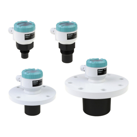
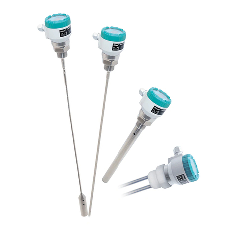
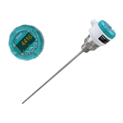
Dinel ULM-70 Series User manual

Read carefully the instructions published in this manual before the rst use of the level meter. Keep the manual
at a safe place. The manufacturer reserves the right to implement changes without prior notice.
INSTRUCTION MANUAL
průmyslová elektronika
Ultrasonic level meters Ulm – 70
Firmware: v.2.0


Table of conTenTs
1 . Measuring principle .................................................................................................................3
2 . Range of applications..............................................................................................................3
3 . Features of variants .................................................................................................................3
4 . Dimensional drawings .............................................................................................................4
5 . Installation instructions ..........................................................................................................5
6 . Electrical connection ...............................................................................................................8
7 . Set-up elements .......................................................................................................................9
8 . Status signalization .................................................................................................................9
9 . Operation and setting ..............................................................................................................10
9 .1 . Basicconguration ............................................................................................................10
9 .2 . Advancedsettings .............................................................................................................12
9 .3 . Additionalfunctions ...........................................................................................................15
10. HART® communication protocol ...........................................................................................18
11 . Order code ..............................................................................................................................18
12 . Accessories ............................................................................................................................18
13 . Safety, protection, compatibility and explosion proof .......................................................19
14 . Use, manipulation and maintenance....................................................................................19
15 . Marking of labels....................................................................................................................20
16 . Menu structure .......................................................................................................................22
17 . Specications.........................................................................................................................23

ULM–70 © Dinel, s.r.o.
3
1 . Measuring principle
UltrasoniclevelmeterULM®isacompactmeasuringdeviceconsistingoftwoparts-mainlevelme-
ter(thebodywithmeasuringelectronics)anddisplaymodule.Usingtheelectroacousticconverter,
thelevelmeterstransmitthesequenceofultrasonicpulsesthatspreadtowardsthesurfacelevel.
Theconverterrecuperatesreectedacousticwavesthataresubsequentlyprocessedintheelec-
tronicmodule.Theintelligentevaluationblockltersoutinterferingsignals,comparesthecleaned
receivedsignalwiththefalsereectionmap(e.g.frommixers,ladders,reinforcementetc.)and
selectsasuitablereection(echo).Basedontheperiodduringwhichtheindividualpulsesspread
towardsthesurfacelevelandbackandbasedonthemeasuredtemperatureinthetank,theinstant
distancetothesurfaceleveliscalculated.Accordingtothelevelheight,thelevelmeteroutputisset
andthemeasuredvalueisdisplayedonthedisplay.
2 . range of applicaTions
Forcontinuousnon-contactlevelmeasurementofliquids(watersolutions,seweragewater,etc.),
mashandpastematerials(sediments,sticks,resinsetc.)inclosedoropenvessels,sumps,reser-
voirsandopenchannels.Incasethelevelofbulk-solidmaterialsismeasured,themeasurement
rangeisreduced.Thelevelmeterscancontinuouslymeasurelevelsofbulk-solidmaterialswith
alowconcentrationofdustparticles.Consultthemanufactureronrecommendeduseofthelevel
meterforbulk-solidmaterials.
3 . feaTures of varianTs
All operations described in this instruction manual have to be carried out only by trained
personnel or an accredited person. Warranty and post warranty service must be exclusively
carried out by the manufacturer.
Improper use, installation or set-up of the level meter can result in crashes in the application
(overlling of the tank or damage of system components).
The manufacturer is not responsible for improper use, losses of work caused by either direct or
indirect damage, and for expenses incurred during installation or use of the level meter.
safeTy
ULM –70_ –02 Measuring range from 0.15m to 2m, plasticPVDFtransmitter,mechanical
connectionwiththreadG1".
ULM –70_–06 Measuring range from 0.25m to 6m, plasticPVDFtransmitter,mechanical
connectionwiththreadG1½".
ULM –70_–10 Measuring range from 0.4m to 10m, plasticPVDFtransmitter,mechanical
connectionwithHDPEpolyethyleneange(version"N")oraluminiumalloy
ange(version"Xi").
ULM–70_–20 Measuring range from 0.5m to 20m, plasticPVDFtransmitter,mechanical
connectionwithaluminiumalloyange.

4
© Dinel, s.r.o. ULM–70
4 . DiMensional Drawings
ULM–70_–02 ULM–70_–06
ULM–70N–10
ULM–70_–20
ULM–70Xi–10
Al alloy, DN65
Al alloy
HDPE, DN65
Pg11 cable gland
Ground terminal

ULM–70 © Dinel, s.r.o.
5
Fig. 2: Level meter dead zone
m – Dead zone
(blind zone, blocking distance)
5 . InstallatIon InstructIons
• Install the levelmeter in thevertical positionintotheupperlidofthetankorreservoirusing
aweldingange,afasteningnutoraangesothatthelevelmeteraxiscanbeperpendiculartothe
surfacelevelofthemeasuredliquid(Fig.1).
• Themin.dimensional parameterstoinstallthelevel
meterintoalidoraceilingofatankaregiveninFig.3.
• Wheninstallinginanopen channel(reservoir,drain
etc.),installthelevelmeterontoabracketascloseas
possibletotheexpectedmax.level.
• Inconnectionwiththemeasurementprinciple,nosig-
nalsreectedintheareaimmediatelyunderthelevel
metercanbeevaluated.The zone(Fig.2)determines
the min. distance possible between the level meter
andthehighestsurfacelevel.Themin.distancesto
themediumaregiveninthechapter"Specications".
• Itis necessary to installthe level meter sothat the
binlevelcannotinterferewiththe deadzonewhen
lled up to the maximum. If the measured level in-
terfereswiththedeadzone,thelevelmeterwill not
workproperly.
Fig. 1: Recommended installation in
the tank
Fig. 3: Installation distance from the tank wall
• If the maximum surface levelin thetank interferes with the dead zone, thelevel meter has
tobemountedintoahigherinstallation neck.Inthisway,thetankcanbellednearlyupto
themaximumvolume.Theinnernecksurfacehastobeevenandsmooth(withoutedgesand
weldedjoints);theinneredgeshouldberoundedwheretheultrasonicwaveleavesthepipe.The
neckdiametershouldbeaslargeaspossiblebuttheneckheightshouldbeaslowaspossible.
RecommendeddimensionsoftheinputneckaregiveninFig.4.
ULM–70–02 ; 10 d > 1/12 c
(min. 200 mm)
ULM–70–06 d > 1/8 c
(min. 200 mm)
ULM–70–20 d > 1/10 c
(min. 200 mm)
Fig. 4: Possible installation of the installation neck
a – Neck height
b – Neck width
m – Dead zone (blind zone, blocking dist.)
ULM–70–02 ; 06 a < 3 b
b > 100 mm
ULM–70–10 a < 1,5 b
b > 100 mm
ULM–70–20 a < 1,5 b
b > 150 mm
d – Distance from
the tank wall
c – Measurement
range of the level
meter

6
© Dinel, s.r.o. ULM–70
• During lling, mixing and other processes, foam
canariseonthesurfacelevelofthemeasuredliq-
uid.Thethickfoamconsiderablyabsorbstheultra-
sonicsignalwhichmightcausemalfunctionofthe
levelmeter(Fig.5).Forsuchcases,itisnecessary
tosetup"SENSITIVITY"modeto"high"orcontact
themanufacturerifneed.
• Iftheemittedacousticsignalofthelevelmeteris
affected by near objects (roughness on walls of
thetank,variouspartitions,mixersetc.),itisnec-
essary to map false reections by activating the
mode "TEACHING". In case of installed mixers,
itisnecessarytoputthemixerstopositionunder
thelevelmeter(directthemixerpaddletotheultra-
sonicsignalbeam).
Fig. 6: False echo from obstacles in the tank
Fig. 5: Thick foam on the surface
• Donotinstallthelevelmeterinorabovethellingpoint(Fig.8).
• Incasethelevelofbulk-solidmaterialsismeasured,themeasurementrangeisreduced.We
recommendtoconsulttheusewiththemanufacturer.
Fig. 7: False echo from the mixer paddle
!
Fig. 8: Level meter installation outside the inuence of lling

ULM–70 © Dinel, s.r.o.
7
Fig. 13: Intensely stirred surface
!
Fig. 10: Prevention to avoid intrusion of
humidity
Fig. 9: Solar radiation shielding cover
• The level meter must not be installed in places
withdirectsolar radiationandmustbeprotected
againstweathereffects.
• Iftheinstallationinplaceswithdirectsolarradia-
tionisinevitable,itisnecessarytomountashield-
ing coverabovethelevelmeter.
• Itissuitabletorunthecableunderacablebush-
ing(obliquelydowninslack)accordingtoFig.10
topreventpenetration of humidity.Thentherain
andcondensingwatercanowofffreely.
• Thecablebushingandconnectorhavetobesuf-
ciently tightenedtopreventpenetrationofhu-
midity.
• To lower the minimum distance to the measured
medium, a reection boardmadefromsolid,
evenandsmoothmaterialcanbeinstalledtothe
levelmeter.Thenthetankcanbellednearlyup
tothemaximumheight.Thesolutionissuitablefor
opentanksandreservoirs.
• Scatteringorattenuationoftheultrasonicsignal
canresultif thesurfacelevelhas been moder-
ately stirredorrippled(byamixer,comingliq-
uid etc.). It can result in reduction of the meas-
urementrangeorunreliablefunctionofthelevel
meter(Fig.12).
• Rotatingmixer bladescancausethatthesurface
is stirred, whichresults infalsereections of the
ultrasonicsignalfromthesurfacelevelandunreli-
ableoperationofthelevelmeter(Fig.13).
Fig. 12: Moderately stirred surface
Fig. 11: Reection board
H + L = Dead zone
(blind zone, blocking dist.)

8
© Dinel, s.r.o. ULM–70
Electrical connection must be done in de-energized state!
With regard to possible occurrence of electrostatic charge on non-conductive parts of
the level meter for explosive areas (ULM–70Xi–_ _–I), level meters must be grounded with
ground terminal! It will be done using a screw placed on the head of the level meter under
the cable bushing.
The voltage source should be preferably realized as a stabilized power supply unit with safe voltage from
18 to 36 V DC (18 ÷ 30 V DC for Xi version), which can be a part of the evaluation or display device.
In case of strong electromagnetic interferences (EMI), parallel cable ducting with power lines, or when
cable length exceeds 30 m we recommended to use shielded cable.
6 . elecTrical connecTion
The ultrasonic level meter is designed to be connected to supply unit or to controller through
acablewiththeouterdiameterof6÷8mm (recommendedcross-sectionofcores0.5 ÷0.75
mm2)bymeansofboltedclipsplacedunderdisplaymodule.Connectthepluspole(+U)tothe
terminal(+),theminuspoleto0Vtotheterminal
(-)andtheshieldingtotheterminal( )(onlyfor
shieldedcables).
Procedure to connect the cable to the level
meter:
1. Unscrewthenutoftheuppertransparentlid.
2. Take the upper edge of the display module
andtakeitoutcarefullybymildswingingup.
3. Ifyoucannotgraspthemodule,youcanuse
a small screwdriver. Insert it as far as the
seamandusefromseveralsidestoslightly
liftthemodule.
4. Release the cable bushing and thread the
strippedsupplycablein.
5. Connect the cable into the bolted clips ac-
cordingtothediagraminFig.14.
6. Assemblethelevelmeterandconnectthe
cabletothesequentialunit.
Fig. 14: Connection diagram of the level meter
Fig. 15: Internal view of terminal block
Display unit connector
Terminal block
Metal clip

ULM–70 © Dinel, s.r.o.
9
8 . sTaTus signalizaTion
1) symbol appears in the lower left corner of the display
display function
"NO ECHO" Lighting intermittently – the level meter is not able to receive echo for a long
time. Incorrect installation of the level meter
"DEAD ZONE" Lighting intermittently – the measured level is in the "dead zone" of the level
meter or the ultrasonic converter is dirty.
"NO PASSWORD" It will appear in the item "MENU" – the level meter is protected using a pass-
word against unauthorised setting. Enter the correct password (see p. 17).
Symbol "T" 1) Lighting permanently – "TEACHING" mode activation.
Symbol "E" 1) Lighting intermittently – correct echo receiving (of the reected signal) from
the measured surface level.
Symbol "L" 1) Lighting permanently – level meter is locked against unauthorized settings by
a password. You must enter the correct password to unlock it (see page 16).
Level meter locked
Ultrasonic transmitter
Upper lid nut
Cable gland
Control buttons
OLED display Label
Fig. 16: Full view of ultrasonic level meter
7 . seT-up eleMenTs
Button
• Set-upmodeaccess
• Conrmationofselectediteminthemenu
• Movethecursorintheline
• Savingofset-updata
Button
• Moveinthemenu
• Changeofvalues
Button
• Cancellingofcarriedoutchanges
• Shiftonelevelup
Echo receiving
Units
Teaching
mode activation
Display
of measured values
Set-up elements

10
© Dinel, s.r.o. ULM–70
BASIC SETTINGS
SERVICE
DIAGNOSTIC
CLONE SETTINGS
PASSWORD
INFO
MIN LEVEL
MAX LEVEL
UNITS
DAMPING
MIN ACTUAL LEVEL
02870mm
OUTPUT: 04.00mA
LEVEL: 06000mm
DISPLAY: 00000%
MAX ACTUAL LEVEL
02870mm
OUTPUT: 20.00mA
LEVEL: 00250mm
DISPLAY: 00100%
STARTING
Dinel®
9 . operaTion anD seTTing
Setthelevelmeterusing3buttonsplacedonthedisplaymodule
(seeChapterSet-upelements).After5min.ofinactivity,thelevel
meterautomaticallyreturnsbacktothemeasurementmode.Ifthe
passwordisactive, the level meter will be alsolocked.Theval-
uesthathavenotbeenconrmedusingthebutton willnotbe
saved!Afterthemeterislocked,youcannotchangethesetting!
Whenyouattempttoedit,thewords"NOPASSWORD"willappear
onthedisplay.Howtounlockthelevelmeterisgivenonpage16.
Afterconnectionofthesupplyvoltagetothelevelmeterthedisplay
showsthelogo"Dinel"andthetext"Starting"(approx.15s).Then,
thelevelmetergoestothemeasuringmodeandthedisplayshows
thecurrentmeasuredvalue.
MIN LEVEL and MAX LEVEL
Youcanfreelydenetheminimum / maximum distance fromthefrontsurfaceofthelevelmeter
(item"LEVEL"),andassigntothisdistanceanycurrent(item"OUTPUT")attheoutputintherange
of4to20mA.The"DISPLAY"isintendedtosetthevaluedisplayedonthedisplay.Settingtheunits
isdoneinthe"UNITS".
For clarity it is advised to assign a minimum
level to current 4 mA and the maximum level
to current 20 mA.
ACTUAL LEVEL: Actual distance to level
OUTPUT: Denition of minimum / maximum
current in mA
LEVEL: Denition of the min / max level
DISPLAY: The value showed on the display
MIN LEVEL
MAX LEVEL
UNITS
DAMPING
UNITS
LEVEL: mm
DISPLAY: %
TEMPERATURE °C
SAVED
Ifinthebottomofthedisplayappears(whenenteringthevalues)theinscription"OUTOFLIMITS",
thevaluespeciedfortheitem"LEVEL"isoutsidethemeasuringrangeofthelevelmeter.Ifthe
inscription"SPANTOOSMALL"isshown,itmustbespeciedalargerspanbetweenMinandMax
values.Formoreinformation,seechapter"Specications".
Thedecimalpointpositionoftheitem'LEVEL'isrmlyset(accordingtotheselectedunits),inthe
item"DISPLAY"itisfreelyadjustable
9 .1 . Basic configuration
Aftertherststartofthelevelmeteritisnecessarytoperformthe
basicconguration(settingofthemeasuringrange,choiceofunits
and possibly damping). The settings are accessible in the basic
menubypressing the"BASICSETTINGS".

ULM–70 © Dinel, s.r.o.
11
UNITS
LEVEL: mm
DISPLAY: %
TEMPERATURE °C
DAMPING
05
UNITS
Levelmetercanprocessandconvertalargenumberofdifferentphysical values.Thesettingis
doneintheitem"UNITS".
MIN LEVEL
MAX LEVEL
UNITS
DAMPING
LEVEL: Unit selection (mm, cm, m, in, ft)
DISPLAY: The unit showed on the display
(%, mm, cm, m, in, ft, l, hl, m3, gal, bbl, mA)
TEMPERATURE: Temperature unit (°C, °F)
DAMPING
Settingthe response timeofthe measurements.The function is useful forsuppressinglevel
uctuations,wavesandrapidchangesofthelevel.Thereactiontimeofthemeasurementwillbe
longerandthelevelmeterwillrespondtorapidchangesinadeneddelayinseconds.
The damping time can be set in the interval
from 0 to 99 s.
1. Toentertothemenupress thesamebuttontoselect"BASICSETTINGS".Then,using
and select"UNITS".
2. Nowthemenuitem"UNITS"isshown. Bypressingthe and buttonmakethesettingsof
individualitems.
3. Bypressing buttonsavethedata.Bynextpressesofthebutton leavethemenu. The
levelmeterreturnstomeasurementmode.
MIN LEVEL
MAX LEVEL
UNITS
DAMPING
1. Toentertothemenupress thesamebuttontoselect"BASICSETTINGS".Then,using
and select"DAMPING".
2. Nowthemenuitem"DAMPING"isshown. Bypressingthe and buttonmakethesettings
ofindividualitems.
3. Bypressing buttonsavethedata.Bynextpressesofthebutton leavethemenu.The
levelmeterreturnstomeasurementmode.
1. Toentertothemenupress thesamebuttontoselect"BASICSETTINGS". Then,using
and select "MINLEVEL"or"MAXLEVEL".
2. Nowitisshowntheitem"MINLEVEL"("MAXLEVEL").Bypressing and settheoutputcur-
rent"OUTPUT",thedistanceforthedenedcurrent"LEVEL"thevalueonthedisplay "DISPLAY".
3. Bypressing buttonsavethe data.Bynextpresses of thebutton leavethemenu.The
levelmeterreturnstomeasurementmode.

12
© Dinel, s.r.o. ULM–70
You can set the sensitivity in three degrees:
LOW – MEDIUM – HIGH.
SENSITIVITY
Thesettingisdenedinthreestepsofthelevelmetersensitivity.
"LOW" – Low sensitivity in case of surrounding interferences affecting the measurement.
"MEDIUM" – Medium sensitivity (suitable for most applications).
"HIGH" – Enhanced sensitivity for measured mediums partly absorbing the ultrasonic signal (bulk-solid mat., foams)
If there are no above obstacles in the tank, it is
not necessary to start this mode.
TEACHING
Themodeservesforsuppressing false reectionsresultingfromreectionoftheultrasonic
signalfromroughnessesonwallsofthetank,variouspartitions,mixersorotherobstacles.The
sensorstartingthismodedetectsfalsereectionsandsavetheminthememory.Thenthesefalse
reectionswillnotaffectthesubsequentmeasurement(theyaremasked).
Before starting the mode it is necessary to empty the tank as much as possible (prefer-
ably completely).
1. Toentertothemenupress thesamebuttontoselect"SERVICE".Then,using and
select"TEACHING".
2. Nowitisshowntheitem"TEACHING".Bypressing setthevalue"LEVELDISTANCE"(dis-
tancetothelevel)–supposeddistancefromthefaceofthesensortothemediumlevel.Ifthe
distancetothelevelisnotpreciselyknown,enteravalueratherlower(inthetoleranceeldas
showninFig.17).
3. Afterenteringthe"SETLEVELDISTANCE"bypressing buttonthesystemstarts"teaching"
(falsereectionmapping).Duringthemapping,thedisplayshowsashingsign"RUNNING".
4. Themappingoffalseechoescanbecompletedwhenyouseetheinscription"PressOKtostop"
andyoupress (seenoteonpage13).
5. Theprocedureiscompletelynishedwhenyoucanseetheinscription"DONE".Itisthenpos-
sibletoexitthemenubyrepeatedpressingthebutton .
9 .2 . advanced settings
In the supplemented conguration, you can set parameters of
sensitivity, mapping of false reections, temperature difference
compensation, behaviour in case of fault conditions or HART®
communication.Here,youcansetthesensorintotheinitialstate
orresetitaswell.Thesettingsareaccessibleinthebasicmenu
undertheitem"SERVICE".
BASIC SETTINGS
SERVICE
DIAGNOSTIC
CLONE SETTINGS
PASSWORD
INFO
SENSITIVITY
MEDIUM
SENSITIVITY
TEACHING
MEDIUM TEMPERATURE
FAILURE MODE
HART
FACTORY DEFAULT
RESET
TEACHING
SET LEVEL DISTANCE:
06000 mm
START
SENSITIVITY
TEACHING
MEDIUM TEMPERATURE
FAILURE MODE
HART
FACTORY DEFAULT
RESET

ULM–70 © Dinel, s.r.o.
13
TEACHING
SET LEVEL DISTANCE:
06000 mm
RUNNING
TEACHING
SET LEVEL DISTANCE:
06000 mm
DONE
PRESS ESC TO EXIT
The mode "TEACHING" will stop automati-
cally after ca. 1000 measurements.
Incaseofinstalledmixers,itisnecessary
topositionthemixersunderthelevelmeter
(directthemixerbladetotheultrasonicsig-
nalbeam).
Note: If there are signicant obstacles in
the upper half of the tank, multiple false
reectionscanoccurespeciallyinclosed
tanks.Insuchcasesitisnecessarytore-
ducethelevelinthetankasmuchsepos-
sibletocorrectlymaskthesepossiblemulti-
plefalsereections. Fig. 17: The "Level distance" zone
1/2 of Tank
Obstacles
Tolerance zone for
"LEVEL DISTANCE" value
TEACHING
SET LEVEL DISTANCE:
06000 mm
RUNNING
PRESS OK TO STOP
MEDIUM TEMPERATURE
Thelevelmeterisequippedwithautomatic temperature compensation.Ifinthetank(openchan-
nel)isabigdifferencebetweenthetemperatureofthemeasuredmedium(liquid)andtemperature
intheplaceofinstallationoftheULM(seemode,"DIAGNOSTICS"page15),itisadvisedtoim-
provetheprecisionofthemeasurementbythezonetemperaturecompensation.Otherwise,this
modeisnot necessary to run.
SENSITIVITY
TEACHING
MEDIUM TEMPERATURE
FAILURE MODE
HART
FACTORY DEFAULT
RESET
MEDIUM TEMPERATURE
YES
+20°C
Inactive compensation (initial state), the
word "NO" appears on the display.
See the "UNITS" menu for temperature unit
selection (°C or °F).
Afterstartofthezonetemperaturecompensationmodeitisnecessarytosetthetemperatureof
thesurfaceofthemedium.Thelevelmeterthencalculatestheaveragevaluefromthemedium
temperatureandthetemperatureattheinstallationplaceofthelevelmeter.Withsuchanaverage
temperatureitcountsincalculatingofthevelocityofacousticwavespropagationandfordetermina-
tionofthelevelposition.
If during the scanning of the tank in the bottom of the display ap-
pears the dialog "press OK to stop" (see gure) the level meter
already found no further obstacles and "TEACHING" mode may be
terminated. If it is not terminated, the level meter is still ready for the
possible presence of obstacles (e.g. paddles of the agitator). Once
it registers a further obstacle, the dialogue disappears and the obstacle is erased. This process may
be repeated up to 1000 cycles. After this the "TEACHING" mode is automatically stopped.
Level Distance

14
© Dinel, s.r.o. ULM–70
NO ECHO: Current in case of echo loss
DEAD ZONE: Dead zone current
The values can be set in three steps:
3.75 mA, 22 mA and LAST (last measured data).
FAILURE MODE
Itdenes the output currentofthelevelmeterwhenthemeasuredmediumlevelisinthedeadzone
("DEADZONE")oroutsidethemeasurementrangeincaseofecholoss("NOECHO").
SENSITIVITY
TEACHING
MEDIUM TEMPERATURE
FAILURE MODE
HART
FACTORY DEFAULT
RESET
FAILURE MODE
NO ECHO: 3.75 mA
DEAD ZONE: 22 mA
HART
HART® mode(pointtopoint,multidrop)andmultidropmodeaddress setting.Upto15unitscanbe
connectedtoonetwo-wiredcableinthemultidropmode.
In case of the address "00", the point to point
mode is enabled. The range from "01" to "15" is
reserved for addresses in the multidrop mode.
After you press the button "RUNNING"
will be displayed for about 3 sec. After the
initial values are set, "DONE" will be appear
on the display.
FACTORY DEFAULT
Toreset the initial values ofthelevelmetersetbythemanufacturer,pressthebutton (seethe
Factorydefaulttable,p.24).
RESET
Complete restartofthelevelmeter.Thesameeffecthasalsoashort-timeinterruptionofthesupply
voltage.Toenabletheresetting,pressthebutton
.
SENSITIVITY
TEACHING
MEDIUM TEMPERATURE
FAILURE MODE
HART
FACTORY DEFAULT
RESET
POLLING ADDRESS
00
FACTORY DEFAULT
ARE YOU SURE?
FACTORY DEFAULT
RUNNING
FACTORY DEFAULT
DONE
PRESS ESC TO EXIT
SENSITIVITY
TEACHING
MEDIUM TEMPERATURE
FAILURE MODE
HART
FACTORY DEFAULT
RESET
SENSITIVITY
TEACHING
MEDIUM TEMPERATURE
FAILURE MODE
HART
FACTORY DEFAULT
RESET
RESET
ARE YOU SURE?
During the restart process, "RUNNING" will
be displayed. Then the level meter will be
automatically turned off and on.

ULM–70 © Dinel, s.r.o.
15
BASIC SETTINGS
SERVICE
DIAGNOSTIC
CLONE SETTINGS
PASSWORD
INFO
DIAGNOSTICS
Itcontainsinformationabouttheactualtemperatureinsidethetank
(or about the compensated temperature) "TEMPERATURE" and
current owing through the loop "CURRENT". If the temperature
compensation("MEDIUMTEMPERATURE")isactivated,thecor-
rectedtemperatureisdisplayed.
TEMPERATURE
CURRENT
TEMPERATURE
+23°C
CURRENT
17.30 mA
The temperature is measured inside the tank
where the level meter is installed.
If the temperature of the measured medium is
different, we recommend you to carry out the
temperature compensation "MEDIUM TEM-
PERATURE" because of accuracy (see p. 15).
Then the displayed temperature is an average
value from the temperature set in the "MEDIUM
TEMPERATURE" and the actual temperature
measured by the sensor.
TEMPERATURE
CURRENT
CLONE SETTINGS
Thismodeisintendedforcopyingofthelevelmeter(ULM–70
body) conguration into the display module (DM–70) and
back.Thedisplaymodulecanthenberemovedfromthelevel
meterbodyandputintoanotherlevelmeterandmaketherethe
settingstransfer(cloning).
The"CLONESETTINGS"modetransfersalldata,excludingsettingofthe"Teaching"andHART®.
BASIC SETTINGS
SERVICE
DIAGNOSTIC
CLONE SETTINGS
PASSWORD
INFO
CLONE SETTINGS
NOW CLONING
CLONE SETTINGS
SENSOR DISPLAY
MODULE
DISPLAY
MODULE
SENSOR
→
→
1. Press toenterthemenuandselecttheitem"CLONESETTINGS".Copyingofthesettings
fromthebodyofthelevelmetertodisplaymoduleisdonebyselecting"SENSOR
→
DISPLAY
MODULE".Totransferthesettingsfromthedisplaymoduletoanotherlevelmeterselecttheitem
DISPLAYMODULE
→
SENSOR.
2. Theselectedmodestartsbypressingbutton Duringtransmissionthedisplayshows"NOW
CLONING".
3. Aftercompletingtheprocessinthemiddleofthescreendisplays"DONE".Itisthenpossibleto
leavethemenuandthemodebypressingthebutton .
CLONE SETTINGS
SENSOR DISPLAY
MODULE
DISPLAY
MODULE
SENSOR
→
→
ARE YOU SURE?
9 .3 . additional functions
Additionalfunctionsincludemodestodisplaytemperatureinthetankortondouttheactualow-
ingcurrentintheloop.Besides,tolockmodicationsusingapasswordandinformationaboutthe
levelmeterversion.Allofthefunctionsareaccessiblefromthemainmenu.

16
© Dinel, s.r.o. ULM–70
CLONE SETTINGS
WARNING–CLONING IS NOT
POSSIBLE
WRONG SENSOR TYPE
PRESS ESC TO EXIT
CLONE SETTINGS
WARNING–CLONING IS NOT
POSSIBLE
NO SETTINGS SAVED
PRESS ESC TO EXIT
Incompatible type of level meter. Transfer of the settings can be realized only
with the same type of level meter (e.g. ULM–70–02 → ULM–70-02,
ULM–70–10 → ULM–70–10) and with the rmware version 2.0 and later.
PASSWORD
Youcanlockthelevelmeterdataagainstunauthorized editing.
Afteractivatingthepasswordthedatamayberead,butcannot
beedited.Ifyoutrytoeditthesettings(withouttruepassword)
thedisplayshows"NOPASSWORD".
Thepasswordcanbeany5-digitnumericcombination.Thecom-
bination of numbers 00000 is reserved for disabling the pass-
word.
1. Usethebuttons and inthemenu"PASSWORD"toselectthemode"ENTER"forentering
thepasswordorthemode"CHANGE"forchangingthepassword(whenactivated,thewordsare
displayedinversely).Pressthebutton onceagaintoconrmtheselection.Youcanchange
thepasswordonlywhenthelevelmeterisunlocked.Otherwise,thewords"NOPASSWORD"
willbedisplayed.
2. Nowyoucaneditthepassword.Theactualediteditemisdisplayedinversely.Pressthebutton
tomovetothenextposition(clockwisedirection),button servestochangethevalues(0...9).
3. Aftertheoperationiscompleted,conrmtheediteddatabypressingthebutton .
Display of status information to conrm data:
"YES" – correctly edited password
"NO" – incorrectly edited password
"OK" – the password saved (only in case of
"CHANGE")
The password is automatically hidden after it
is edited or changed ("00000" will appear).
To deactivate the password, edit the nu-
merical combination "00000" in the mode
"CHANGE".
TEACHING
SET LEVEL DISTANCE:
06000 mm
START
NO PASSWORD
PASSWORD
ENTER
00000
PASSWORD
CHANGE
00000
BASIC SETTINGS
SERVICE
DIAGNOSTIC
CLONE SETTINGS
PASSWORD
INFO
The data set is not stored into the display module (DM–70). The transfer can
not be done. It is necessary to repeat the procedure of the copying the settings
in the mode "CLONE SETTINGS".
The level meter with activated password will be automatically locked after 5 minutes of inactivity or after
5 min. from switching to measuring mode. Locking of level meter is indicated in the lower left corner
of the screen by the letter "L".
If the password is lost, contact the manufacturer.

ULM–70 © Dinel, s.r.o.
17
INFO
Informationaboutthetype,serialnumberandproductiondateofthelevelmeter(type,serialnumber–
SNandrmwareversion–SW).
SENSOR
ULM-70N-06-I HART
SN: 110025
SW: 2.0
DISPLAY MODULE
DM-70
SN: 110041
SW: 2.0
SENSOR
DISPLAY MODULE
SENSOR
DISPLAY MODULE
BASIC SETTINGS
SERVICE
DIAGNOSTIC
CLONE SETTINGS
PASSWORD
INFO
The display modules DM–70 with rmware version 2.0 and later are not backwards compatible with
ULM–70 body with rmware versions 1.0, 1.1 and 1.2.

18
© Dinel, s.r.o. ULM–70
10 . orDer coDe
11 . HarT® coMMunicaTion proTocol
Universalcommunicationinterfacefordatacommunicationofperipheraldeviceswiththelevel
meter.Datatransmissionrunsthroughthesamelineasthe4÷20mAcurrentloopwithoutimpact
onanalogcommunication.
Fig. 18: Typical hardware conguration with HART®
HART®
Modem
USB / RS232
HART®
communicator
ULM–70
PC
≈ 250 R Power supply unit
12 . accessories
Standard – incl. in the price of the level sensor Optional – for extra charge
• 1pcofSeal(forULM–70_–02–I,06–I) • FixingnutsG1"andG1½"
• HornadapterST–G1andST–G1,5
Performance:
Maximum range:02 – 0.15 ... 2 m
06 – 0.25 ... 6 m
10 – 0.4 ... 10 m
20 – 0.5 ... 20 m
N– Normal – usable in non-explosive areas only
Xi – Ex. proof – suitable for explosive areas
ULM – 70 –
Output type: I – Current
––BVersion without Display module
The device must be installed to prevent tensile overload rope electrode level meter.

ULM–70 © Dinel, s.r.o.
19
It is forbidden to perform any modications or interventions into the ULM–70 level meter
without manufacturer's approval. Potential repairs must be carried out by the manufacturer
or by a manufacturer authorized service organization only.
Installation, commissioning, operation and maintenance of the ULM–70 level meter has to
be carried out in accordance with this instruction manual; the provisions of regulations in
force regarding the installation of electrical equipment have to be adhered to.
13 . safeTy, proTecTion, coMpaTibiliTy anD explosion proof
ThelevelmeterULM–70isequippedwithprotectionagainstreversepolarityandoutputcurrent
overload.
Protectionagainstdangerouscontactissecuredbylowsafetyvoltagethatcomplieswith
EN332000-4-41.
ElectromagneticcompatibilityaccordingtoEN55022/B,EN61326/Z1andEN61000-4-2to6.
ExplosionproofofULM–70Xitypecomplieswiththefollowingstandards:EN60079-0:2007;
EN60079-11:2007;EN60079-26:2007andexaminedbyFTZÚ-AO210Ostrava-Radvanice
certicateNo.:FTZÚ09ATEX0277X.
Special conditions for safe use ULM–70Xi:
ThedeviceisdesignedforconnectiontotheisolatingrepeaterIRU-420.Whentheotherapproved
supplyunitisused,whoseoutputparameterssatisfyabovementionedoutputparameters,itisneces-
sarytohaveagalvanicseparationor,ifsupplyunitwithoutgalvanicseparationisused(Zenerbarri-
ers),itisnecessaryprovidepotentialequalizationbetweensensorandpointofbarrierearthing.
Forapplicationinzone0thepresentexplosiveatmospheres-mixtureofairwithammablegases,
vapourormistsmustcomply:-20°C<Ta<+60°C;0,8bar<p<1,1bar
The device must be installed in such a way, to prevent mechanical damage of sensor face.
14 . use, ManipulaTion anD MainTenance
Thelevelmeterdoesnotrequireanypersonnelforitsoperation.Follow-updisplayingdeviceis
usedtoinformthetechnologicalentityoperatingpersonnelonthemeasuredsubstancelevelheight
duringtheoperation.
Maintenanceofthisequipmentconsistsinvericationofintegrityofthelevelmeterandofthesup-
plycable.Dependingonthecharacterofthesubstancemeasured,werecommendtoverifyatleast
onceperyeartheclarityoftheultrasoundtransduceremittingeldandtocleanit,respectively.In
caseanyvisibledefectsarediscovered,themanufacturerorresellerofthisequipmentmustbe
contactedimmediately.
This manual suits for next models
12
Table of contents
Other Dinel Measuring Instrument manuals

Dinel
Dinel ULM-53L User manual
Dinel
Dinel ULM-53 series User manual

Dinel
Dinel ULM-53 series User manual

Dinel
Dinel CLM-36 User manual
Dinel
Dinel CLM-36-10 User manual
Dinel
Dinel ULM-53 series User manual

Dinel
Dinel MLM-35 User manual
Dinel
Dinel CLM-36 User manual

Dinel
Dinel CLM-36 User manual

Dinel
Dinel ULM-53 series User manual

