Dinel CLM-70 User manual

Before the rst use of the level meter , read the instructions in this manual and keep it
carefully. The manufacturer reserves the right to make alterations without a prior notice.
Capacitive level meter
CLM–70
INSTRUCTION MANUAL
Applies to rmware version 1.0


Contents
1. Safety.............................................................................................................................................4
2. Basic description.........................................................................................................................4
3. Range of application ..................................................................................................................5
4. Variants of sensors ....................................................................................................................5
5. Dimensional drawings ..............................................................................................................6
6. Installation and putting into operation ...............................................................................8
7. Installation instructions ...........................................................................................................8
8. Electrical connection ............................................................................................................. 13
9. Setting elements...................................................................................................................... 14
10. Setting the level meter .......................................................................................................... 15
10.1. Basic settings.................................................................................................................. 15
10.2. Service settings............................................................................................................... 18
10.3. Additional functions ...................................................................................................... 19
11. HART®protocol......................................................................................................................... 21
12. How to install a custom measuring electrode, replace or shorten the electrode..........22
13. Order code................................................................................................................................. 24
14. Failure status indication........................................................................................................ 24
15. Accessories................................................................................................................................ 25
16. Safety, protection, compatibility and explosion proof................................................... 25
17. Use, manipulation, and maintenance ................................................................................ 25
18. Marking of labels ..................................................................................................................... 26
19. Menu structure ........................................................................................................................ 27
20. Technicalspecications ......................................................................................................... 28
21. Error codes ................................................................................................................................ 31
22. Packing, shipping and storage.............................................................................................. 31

CLM–70 © Dinel, s.r.o.
4
Capacitive level meters CLM-70 are compact measuring devices consisting of the level meter
body and a measuring electrode. The level meter body contains measurement electronics
and a display module. The electronics measure the electrical capacity of the electrode system,
which is dependent on the level height. The level meter’s electrical output corresponds to the
capacity (level height) and the measured data are shown on the meter’s display.
The level meter can be adjusted by the display module positioned under the transparent lid.
The level meter has 4–20mA current output with HART®communication. The level meter is
power supplied using a cable connected to the terminal block located under the display and
adjustment module.
Level meters are available in several measuring electrode modications (rod and rope-type
electrodes). Electrodes may be coated with insulation, which is important for their functioning
in the case of adherent, electrically conductive and aggressive media. Rod electrodes are
also available in a version provided with a reference tube or a pair of parallel electrodes for
measuring liquids in non-conductive tanks.
All operations described in this instruction manual have to be carried out by trained
personnel or by an accredited person only. Warranty and post warranty service must
be exclusively carried out by the manufacturer.
Improper use, installation or set-up of the sensor can lead to crashes in the ap-
plication.
The manufacturer is not responsible for improper use, loss of work caused by either
direct or indirect damage, and for expenses incurred at the time of installation or
during the period of use of the level sensors.
To ensure maximum safety of control processes, we have dened the following safety instruc-
tions and information. Each instruction is labelled with the appropriate pictogram.
Alert, warning, danger
This symbol informs you about particularly important instructions for installation and
operation of equipment or dangerous situations that may occur during the installation
and operation. Not observing these instructions may cause disturbance, damage or de-
struction of equipment or may cause injury.
Information
This symbol indicates particularly important characteristics of the device.
Note
This symbol indicates helpful additional information.
Used symbols
1 . safety
2 . basiC desCription

5
© Dinel, s.r.o. CLM–70
• CLM–70_–00 Without electrode; customer makes an electrode himself (types 10
or 30 only) and attaches it to the electrode holder using M8 threaded
connection.
• CLM–70_–10 Uncoated stainless steel rod electrode for level measurement of
electrically non-conductive liquids (oils, diesel fuel) and bulk solids (our,
sand, cement, granulated plastic materials, etc.). Length 0.2 ... 8 m.
• CLM–70_–11 Coated stainless steel rod electrode (PFA) with enhanced resistance
to penetration (diusion) of vapours and gases. For level measurement
of water and other electrically conductive liquids in food processing,
pharmaceutical, and chemical industries. It can be used temporarily for
high-temperature applications (e.g. sanitization with hot steam) or for
volatile aggressive liquids, etc. Length 0.2 ... 3 m.
• CLM–70_–12 Coated stainless steel rod electrode (FEP), suitable for level measure-
ment of water and other electrically conductive liquids. Also suitable for
impure liquids in metallic tanks, concrete sumps, etc. Length 0.2 ... 3 m.
• CLM–70_–13 Semi-coated stainless steel rod electrode (FEP) for level measurement
of electrically non-conductive liquids in environments where partial
condensation of vapours on the electrode may occur. Length 0.5 ... 8 m.
• CLM–70_–20 Uncoated stainless steel rod electrode with reference tube for level
measurement of unpolluted and electrically non-conductive liquids (oil,
diesel fuel, petrol). Length 0.2–3 m.
• CLM–70_–22 Coated stainless steel rod electrode (FEP) with reference tube for level
measurement of clean electrically conductive liquids (e.g. in plastic and
glass tanks) and for higher measuring accuracy. Length 0.2 ... 3 m.
• CLM–70_–30 Uncoated stainless steel rope electrode and weight for level
measurement of bulk solids and powders (sand, our, cement, etc.). The
rope can also be shortened. Length 1 ... 20 m.
• CLM–70_–31 Uncoated stainless steel rope electrode and coated dynamic anchor
for measurement of bulk solids in taller silos. Length 1 ... 20 m.
• CLM–70_–32 Fully coated stainless steel rope electrode and weight (FEP rope
insulation, PTFE weight insulation), designed for level measurement of
water and other electrically conductive liquids. Length 1 ... 12 m.
• CLM–70_–61 Two coated stainless steel rod electrodes (FEP electrode insulation,
PTFE head) for level measurement of aggressive liquids. Length 0.2 ... 2 m.
4 . Variants of sensors
3 . range of appliCation
The capacitive level meters are suitable for continuous level measurement of various liquids
and solid materials. The level meters are resistant to any changes in the atmosphere above the
level (vacuum, overpressure, steam, or dust).
CLM–70 © Dinel, s.r.o.
6
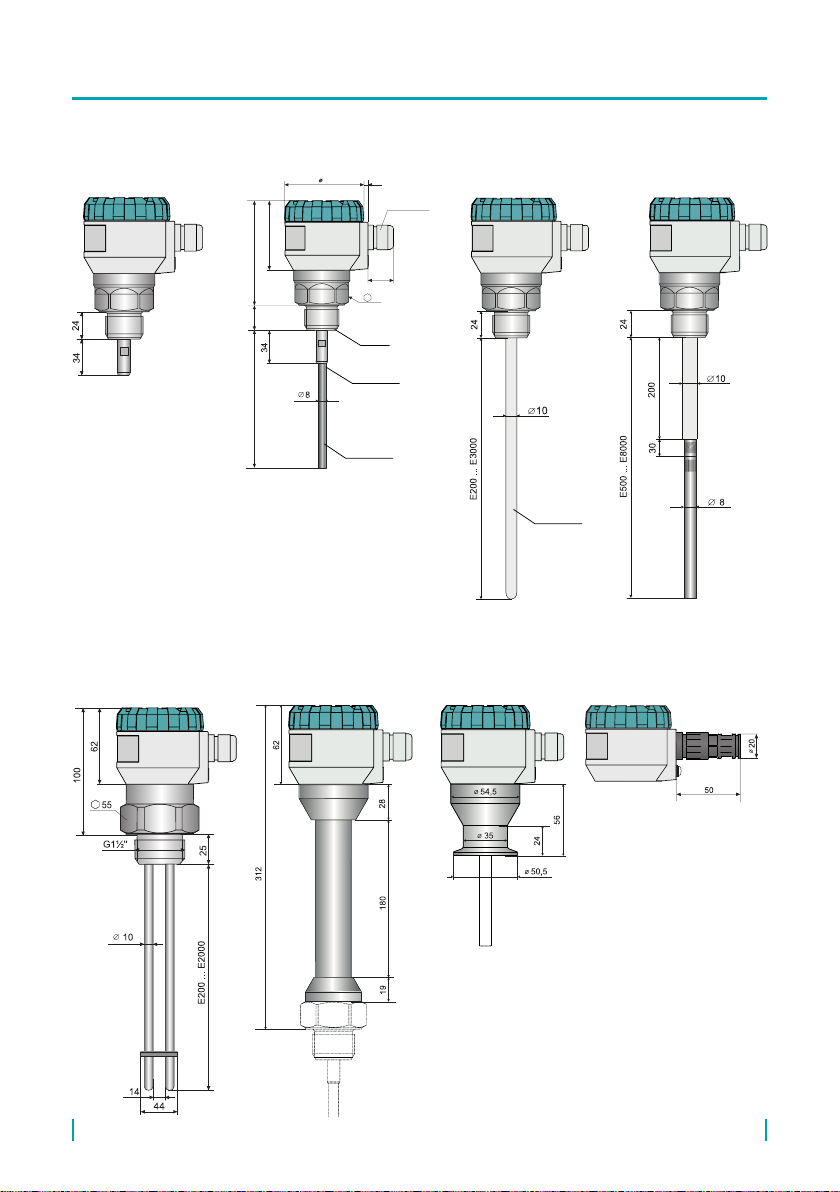
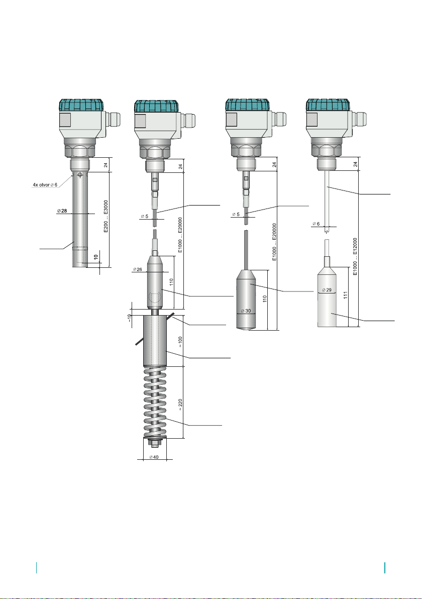
5 . dimensional drawings
CLM–70_–10CLM–70_–00 CLM–70_–13CLM–70_–11, 12
E200 ... E8000
24 97
62
70 4
M16x1,5
27
46
electrode
holder
electrode
thread*
coated
electrode
CLM–70_–61 Variant CLM-70
with a cable gland
for protective hose
High temperature
performance
CLM–70_T**
Process connection
Tri-clamp***
* types of thread: G1" (except type 61),
1″ NPT (except type 61)
** Except type CLM–70_–61
*** Only for type CLM–70_–11(12, 13, 32)
7
© Dinel, s.r.o. CLM–70
CLM–70_–20, 22
reference
pipe
CLM–70_–30CLM–70_–31 CLM–70_-32
compression
spring
hopper wall
(KV–31, PR–31)*
anchor
with ball joint
rope
electrode
coated rope
electrode
coated
weight
rope
electrode
weight
* anchor roll KV–31 or dust proof bushing
PR–31 (see accessories)
CLM–70 © Dinel, s.r.o.
8
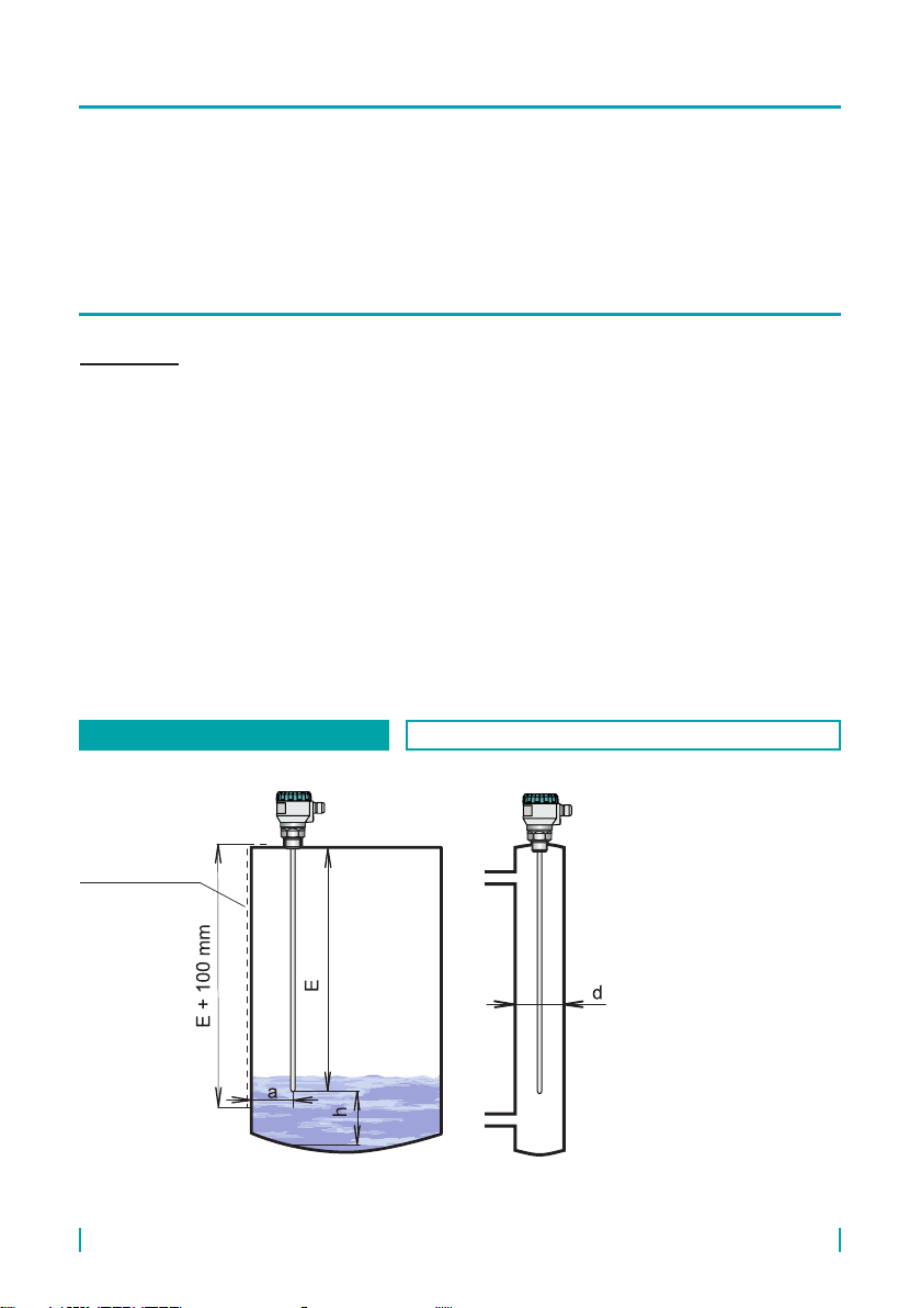
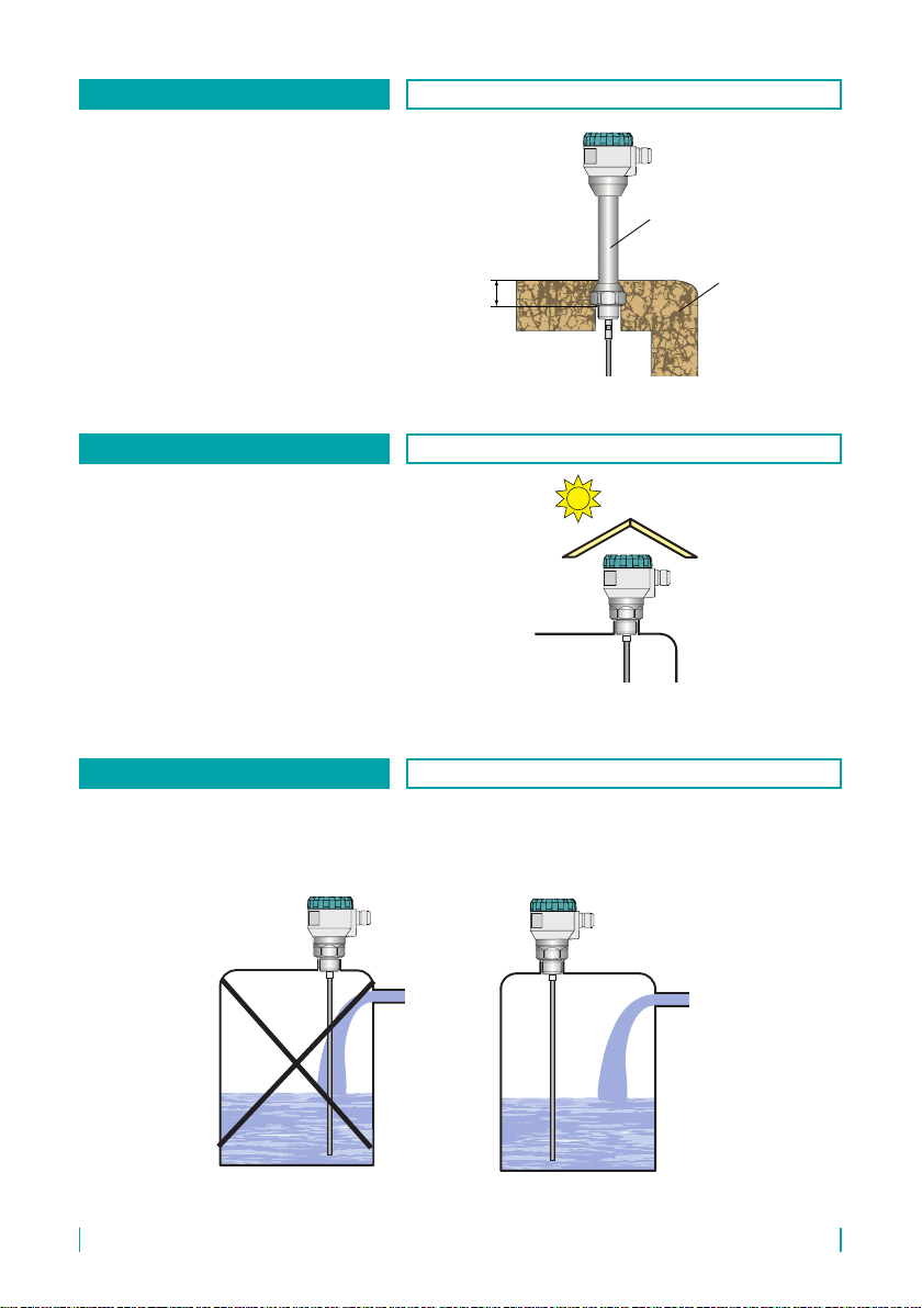
BASIC INFO
• The level meters with an insulated electrode are equipped with a protective cap at the
electrode end, which must be removed before installation.
• The level meters are mounted vertically into the upper lid of the tank or hopper or on xing
brackets using a welding ange for a xing nut or a Clamp-type ange.
• When installing the level meter in a metal tank or hopper, the housing is not necessary to
be grounded separately.
• In the case of installation in concrete sumps or silos, the level meter is advisable to
be installed on an auxiliary metal structure (bracket, lid, etc.) and then connected to
a permanently submerged metal object or steel reinforcements in concrete (armouring).
E - electrode length [mm] –
select so that the electrode
end is submerged at least
20 mm below the lowest
measured level
h - distance from the bottom
– at least 50 mm
a - distance from the wall – at
least approx. E/20
d - diameter of the auxiliary
tubular vessel – at least 40
+ E/20 (smaller dimensions
must be discussed)
Auxiliary electrode
width = minimum
30 mm
(required for non-
metal vessels only)
Fig. 1: Installation of level meters with rod electrodes
6 . installation and pUtting into operation
This procedure has the following three steps:
• installation instrUCtions
• eleCtriCal ConneCtion
• settings
7 . installation instrUCtions
METAL AND NON-METAL VESSELS APPLIES TO: CLM-70_-10, 11, 12, 13

9
© Dinel, s.r.o. CLM–70
h- distance from the
bottom – at least 50
mm due to the possible
presence of heavier
fractions (water) in
petroleum products
k - distance from the wall –
arbitrary
Fig. 2: Installation of the level meter with a reference tube
VARIANTS WITH A REFERENCE TUBE APPLIES TO: CLM-70_-20, 22
DEEP METAL AND CONCRETE SILOS APPLIES TO: CLM-70_-30, 32
To be connected to
the armouring
Concrete silo
Metal tank
E- electrode length [mm] – to be selected so that the electrode end is placed at least 20 mm
below the lowest measured level
h- distance from the bottom – at least 100 mm
a- distance from the wall – at least E/20; otherwise, choose as large as possible (as far from
the wall as possible) in the middle between the wall and the vertical drain
Fig. 3: Installation of level meters with rope electrodes
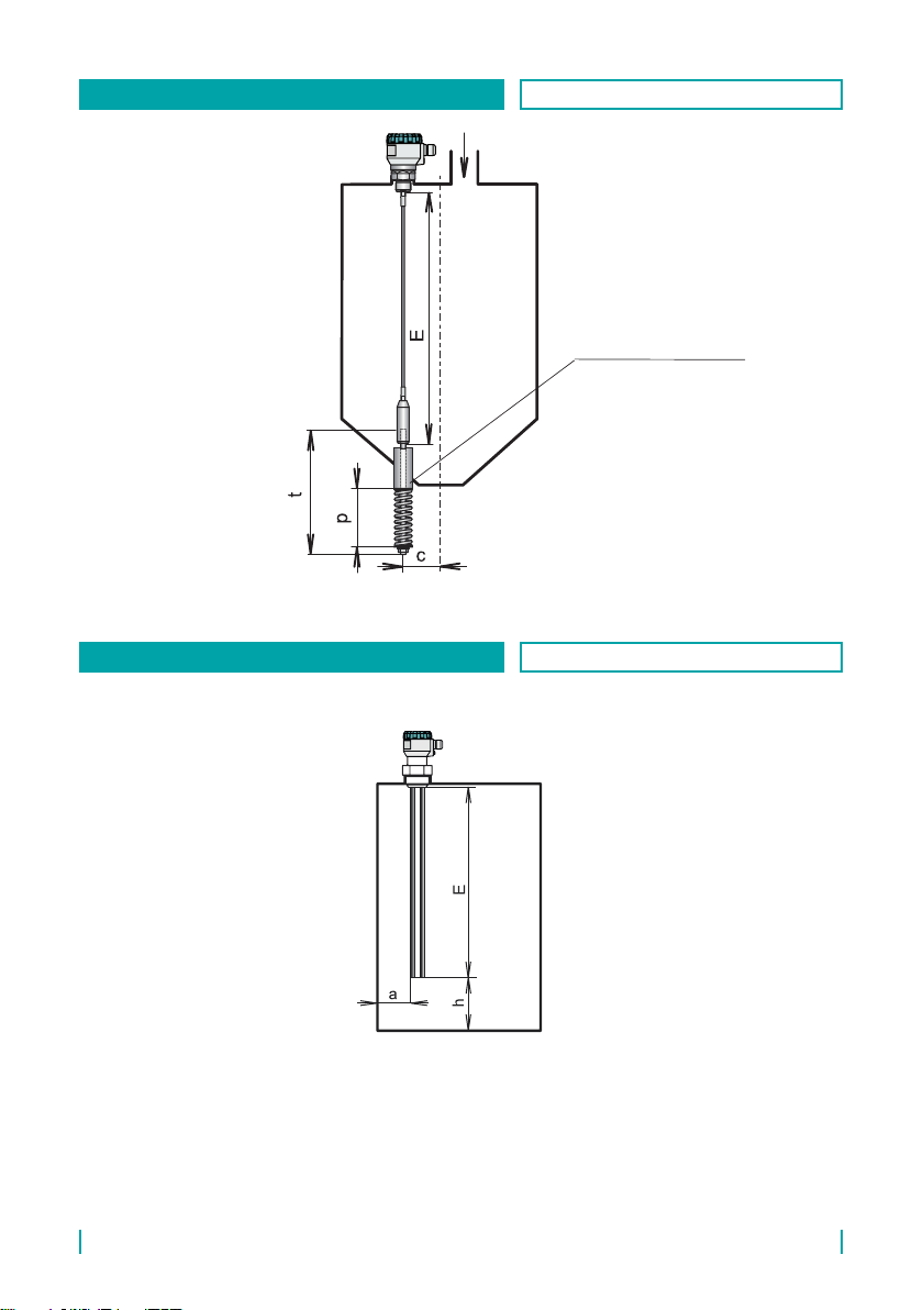
CLM–70 © Dinel, s.r.o.
10
E- electrode length [mm]
t- guide rod length – approx.
500mm
p- compression spring length
– approx. 200 mm
c- distance from the hopper
axis (choose the minimum
one, if possible)
Anchor welding cylinder
(mat. 11375) or the
dust-tight bushing to the
hopper casing
Fig. 4: Installation of the level meter with arope electrode and anchor
E – electrode length [mm] –
submerge the electrode
end at least 20 mm below
the lowest measured level.
h – distance from the bottom
(at least 30 mm)
a – distance from the wall (at
least E/20)
Fig. 5: Installation of the level meter with a reference electrode
ROPE ELECTRODE WITH AN ANCHOR APPLIES TO: CLM-70_-31
AGGRESSIVE LIQUIDS, NON-METAL VESSELS APPLIES TO: CLM-70N-61
11
© Dinel, s.r.o. CLM–70
Heat insulation
50
high-temperature
extension
• The level meter must not be in-
stalled in places exposed to direct
sunlight and must be protected
from the weather inuences. Even
so installation is in exposed places
to direct sunlight a shielding cov-
er is necessary to be tted over
the level meter (see Fig. 7).
• The level meters for high operat-
ing temperatures are equipped
with an extension. This is used to
thermally insulate the electronics
part of the meter from the high
operating temperature. The ex-
tension must not be embedded in
the insulation more than 50 mm.
Fig. 7: A shielding cover protecting against direct sunlight
Fig. 6: Installation of the level meter in an insulated tank
COVERING THE LEVEL METER APPLIES TO: All types
TANK WITH INSULATION APPLIES TO: CLM-70NT-_
• The level meter is not recommended to be installed at or above the lling point. Measure-
ment may be inuenced by the inow medium.
Fig. 8: Installation of the level meter out of the reach of lling ow
OUT OF REACH OF FILLING APPLIES TO: All types

CLM–70 © Dinel, s.r.o.
12
• The level meter of the CLM-70_-
00 type is provided without a
measuring electrode. Therefore,
the measuring electrode is nec-
essary to be made and mounted
to the level meter body. The elec-
trode diameter must be between
8–10 mm. For connection, the
electrode must have an M8 male
thread. For the connection proce-
dure, see chapter 12, p. 22. Fig. 10: The level meter without an electrode
For the level meter of the CLM-70_-00 type, the manufacturer is not responsible for
defects related to the connected measuring electrode!
It is intended for non-conductive media only, as only a non-insulated rod or rope
can be connected.
VARIANT WITHOUT AN ELECTRODE APPLIES TO: CLM-70_-00
• It is advisable to run the cable un-
der a cable gland (sagging down-
wards). This prevents possible
ingress of moisture through the
cable gland. Rain and condensing
water can ow freely downwards,
see Fig.9.
• The cable gland and the top lid
must be suciently tightened
to prevent moisture ingress. Fig. 9: Preventing moisture from ingress
through the cable gland
MOISTURE APPLIES TO: All types
13
© Dinel, s.r.o. CLM–70
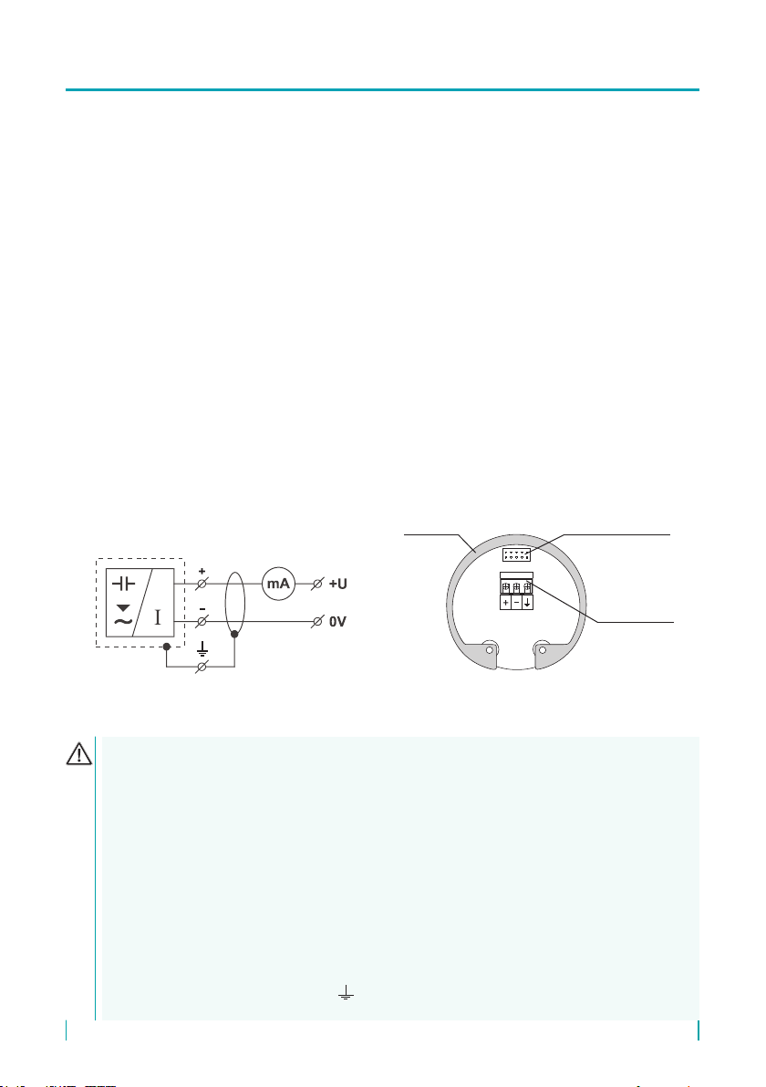
8 . eleCtriCal ConneCtion
The level meter is connected to the follow-up (evaluation) device using a suitable cable with
an outer diameter of 6–8 mm by means of screw terminals located under the display module.
The recommended wire cross-section is 2× 0.5–0.75 mm2 (shielded) for the current version.
The positive pole (+U) is connected to the (+) terminal, the negative pole (0 V) to the (-) terminal,
and the shield (only for shielded cables) is connected to the ( ) terminal.
To connect a cable to the level meter:
1. Unscrew the upper lid nut.
2. Grasp the top edge of the display module and carefully slide it upwards carefully by slightly
swinging it.
3. If you are unable to grasp the display module, a small screwdriver can be used – insert it under
the edge and slightly lift the module from several sides.
4. Loosen the cable gland to pass a stripped power cable inside.
5. Connect the cable to threaded terminals, as shown in the diagram in Fig.11. Tighten the termi-
nals and cable gland rmly. For the tightening torque, see the Technical Specications.
6. Return the display module into the head until the connector is connected correctly.
7. Slide the silicone seal onto the level meter body thread and tighten the upper lid nut rmly.
Connect the cable to the downstream device.
display connector
threaded ter-
minals
metal
clip
Fig. 12: Internal view of threaded terminals of level meter
with current output CLM-70_-_-_-I
Fig. 11: Connection diagram of level meter
with current output CLM-70_-_-_-I
Electrical connection can only be made in a voltage-free state!
The power supply must be designed as a stabilized source of low safe voltage with
galvanic isolation. If a switched power supply is used, its design must eectively sup-
press common mode interference. If the switched power supply is equipped with a
PE protective terminal, it must be earthed without fail!
If the sensor is to be installed in an outdoor environment more than 20 m from an
outdoor switchboard or an enclosed building, the electrical supply to the sensor must
be supplemented with suitable overvoltage protection.
In case of a strong environmental electromagnetic interference, common routing of
the signal cable with the power cable or in case of more than 30 m in length, we
recommend grounding the level meter and using a shielded cable. Ground the cable
shielding on the side of power supply or connect it to the internal connection termi-
nal of the level meter marked as , see Figs. 22 and 23 (the cable shielding should
always be connected in one point).

CLM–70 © Dinel, s.r.o.
14
9 . setting elements
Button
• access to the setting menu
• acknowledgement of the
selected menu item
• cursor movement in line
• saving settings
Button
• navigation in menu
• changing values
Button
• cancelling changes
• moving up a level
units
display
of measured values
display
error codes
setting
elements
level meter
locked
Setting is done using the 3 buttons located on the DM-70 display module. All setting items are
available in the level meter menu.
* ashes intermittently when receiving a reected
signal (echo) from the measured level
warning and
information signs
The level meter, type CLM-70_-__-_-_-_-L, is supplied without the DM-70 display
module. To set up the level meter it is necessary to connect a display module (or it
can be congured via HART). When the set-up is complete, the display module can
be disconnected and the level meter takes measurements without it.
• Status indication (lower left corner of the display):
symbol -lights permanently - the level meter is locked against unauthorized
settings; a password is required for unlocking (see MENU – PASSWORD)
• Warning signs:
FIXED OUTPUT - the output current is xed to a constant value (see MENU – DIAGNOS-
TIC – CURRENT)
LOW POWER - low supply voltage (it must be within the specied range – see TECH-
NICAL SPECIFICATIONS)
NO PASSWORD - when changing the locked level meter settings
NO DATA AVAILABLE - display module doesn't communicate with the electronics of
the level meter (e.g. incorrectly inserted display module into
connector or measuring module is not functional).
• Information signs:
CAPACITY - actual capacity displayed (see DIAGNOSTIC – CAPACITY)
CURRENT - actual current displayed (see DIAGNOSTIC – CURRENT)
• Error codes:
(see chapter 21. Error Codes)

15
© Dinel, s.r.o. CLM–70
10 . setting the leVel meter
UNITS
LEVEL: mm
DISPLAY: %
TEMPERATURE °C
STARTING
Dinel®
The level meter is controlled by 3buttons located on the re-
movable DM-70 display module (see the Control Units chapter,
p. 14).
Saving of values is indicated by the word “SAVED” at the display
bottom (see Fig.). Values that have not been conrmed with the
ESC OK
www.dinel.cz
Ultrasonic Level Meter ULM-70
ESC
OK
1745
mm
button will not be saved! After inactivity lasting 5 min-
utes, the level meter automatically goes back to the measuring
mode. If the password is active, the level meter locks besides.
No changes in settings are possible to be made after locking!
When attempting to edit, “NO PASSWORD” appears on the dis-
play. How to unlock, see p. 20.
After connecting the supply voltage, the manufacturer's logo
and the text “Starting” appear on the level meter display. Then, the level meter goes into the
measuring mode, and the actually measured value is displayed.
MIN CAPACITY (MAX CAPACITY)
Here, the CAPACITY range (in the CAPACITY line), within which the level meter should meas-
ure, must be set. The output current range (the OUTPUT line) of 4mA/20mA output is then
assigned to this range. And the value shown on the meter display (DISPLAY line).
In the upper right corner below the sign “ACTUAL CAPACITY”, the value of the currently meas-
ured level is displayed.
ACTUAL CAPACITY: current meas-
ured capacity
CAPACITY: denition of the min/max
capacity
DISPLAY: the value show on the
display
BASIC SETTINGS
SERVICE
DIAGNOSTIC
CLONE SETTINGS
PASSWORD
INFO
SAVED
UNITS
CAPACITY: PF
DISPLAY: %
SAVED
STARTING
BASIC SETTINGS
SERVICE
DIAGNOSTIC
CLONE SETTINGS
PASSWORD
LANGUAGE
INFO
MIN CAPACITY
MAX CAPACITY
UNITS
DAMPING
SENSITIVITY
TEACHING
MIN ACTUAL CAPACITY
023.56 pF
OUTPUT: 04.00 mA
CAPACITY: 013.33 pF
DISPLAY: 00000 %
MAX
OUTPUT: 20.00 mA
CAPACITY: 157.77 pF
DISPLAY: 00100 %
MIN CAPACITY
MAX CAPACITY
UNITS
DAMPING
SENSITIVITY
TEACHING
10 .1 . Basic settings
After the rst start of the level meter, the basic conguration
(setting of the measuring range, selecting units and possible
damping) must be performed. The settings are accessible in
the basic menu by pressing the
ESC OK
www.dinel.cz
Ultrasonic Level Meter ULM-70
ESC
OK
1745
mm
button under “BASIC SET-
TINGS”.
ACTUAL CAPACITY
023.56 pF
CLM–70 © Dinel, s.r.o.
16
CAPACITY: pF
DISPLAY: %
CAPACITY: only units pF
DISPLAY: the unit shown on the
display (%, mm, cm, m, in, ft, l, hl, m3,
gal, bbl, and mA)
The damping time can be set within
the interval of 0 to 99 seconds.
1. Press the
ESC OK
www.dinel.cz
Ultrasonic Level Meter ULM-70
ESC
OK
1745
mm
button to enter the menu; use the same button to select “BASIC SETTINGS”.
Then, use the
ESC OK
www.dinel.cz
Ultrasonic Level Meter ULM-70
ESC OK
1745
mm
and
ESC OK
www.dinel.cz
Ultrasonic Level Meter ULM-70
ESC
OK
1745
mm
buttons to select “UNITS”.
2. Now, the “UNITS” item is displayed. Use the
ESC OK
www.dinel.cz
Ultrasonic Level Meter ULM-70
ESC
OK
1745
mm
and
ESC OK
www.dinel.cz
Ultrasonic Level Meter ULM-70
ESC OK
1745
mm
buttons to set each item.
3. After nishing the settings, press the
ESC OK
www.dinel.cz
Ultrasonic Level Meter ULM-70
ESC
OK
1745
mm
button to save the data. Press the
ESC OK
www.dinel.cz
Ultrasonic Level Meter ULM-70
ESC
OK
1745
mm
button suc-
cessively to exit the menu; the level meter returns to the measuring mode.
1. Press the
ESC OK
www.dinel.cz
Ultrasonic Level Meter ULM-70
ESC
OK
1745
mm
button to enter the menu; use the same button to select “BASIC SETTINGS”.
Then, use the
ESC OK
www.dinel.cz
Ultrasonic Level Meter ULM-70
ESC OK
1745
mm
and
ESC OK
www.dinel.cz
Ultrasonic Level Meter ULM-70
ESC
OK
1745
mm
buttons to select “DAMPING”.
2. Now, the “DAMPING” item is displayed. Use the
ESC OK
www.dinel.cz
Ultrasonic Level Meter ULM-70
ESC
OK
1745
mm
and
ESC OK
www.dinel.cz
Ultrasonic Level Meter ULM-70
ESC OK
1745
mm
buttons to set damping.
3. After nishing the settings, press the
ESC OK
www.dinel.cz
Ultrasonic Level Meter ULM-70
ESC
OK
1745
mm
button to save the data. Press the
ESC OK
www.dinel.cz
Ultrasonic Level Meter ULM-70
ESC
OK
1745
mm
button suc-
cessively to exit the menu; the level meter returns to the measuring mode.
A) THE SETTING METHOD AT LIMIT POINTS OF RANGE (if the tank is possible to be completely
emptied and ooded with a medium) – this method is preferred
UNITS
MIN CAPACITY
MAX CAPACITY
UNITS
DAMPING
DAMPING
05
MIN CAPACITY
MAX CAPACITY
UNITS
DAMPING
DAMPING
The time constant of the output variable lter is set here. The time constant is given in sec-
onds. The response progress of the output variable to a step change of the level is exponential.
The time constant indicates the time, within which the output value reaches approximately
63% of the maximum value.
Higher values are useful for suppressing display uctuations during rapid changes (whirling
level). Conversely, if a rapid response is required, a low damping value must be set.
The damping time can be set within the interval of 0 to 99 seconds.
SETTING PROCEDURE FOR THE LEVEL METER
The level meter must be installed properly in the tank and connected to the power supply.
Then, the basic level meter settings can be made.
UNITS
The CAPACITY line – the units, in which the measuring and adjustment of the level meter (pF)
takes place
The DISPLAY line – the setting of the units to be displayed on the main display screen (%; pF;
mm; cm; m; in; ft; l; hl; m3; gal; bbl; and mA).

17
© Dinel, s.r.o. CLM–70
1. Bring the measured medium to the minimum capacity. In the BASIC SETTINGS – MIN CA-
PACITY menu, the value of electrical capacity measured by the level meter in real time is
displayed in the upper right corner under the sign “ACTUAL CAPACITY”. This value must be
copied to the CAPACITY line. The value which is shown on the display at this minimum capac-
ity is entered in the DISPLAY line. The OUTPUT line is not editable and displays the value of
an output variable at the minimum capacity.
2. Bring the measured medium to the maximum capacity. In the BASIC SETTINGS – MAX CA-
PACITY menu, the value of electrical capacity measured by the level meter in the real time is
displayed in the upper right corner under the sign “ACTUAL CAPACITY”. This value must be
copied to the CAPACITY line. The value which is shown on the display at this maximum ca-
pacity is entered in the DISPLAY line. The OUTPUT line is not editable and displays the value
of an output variable at the maximum capacity. The conversion to the shown value on the
display and the output (current) is always linear depending on the capacity to be measured.
3. In the BASIC SETTINGS – UNITS menu, the required units for display on the main screen of
the meter display are set in the DISPLAY line. The CAPACITY line is not editable and indicates
in which units the level meter measures the capacity.
4. The time constant of the output variable lter is set in the BASIC SETTING – DAMPING menu.
B) THE SETTING METHOD AT ANY POINT WITHIN THE RANGE (if the tank cannot be completely
emptied or ooded with a medium)
1. Flood the tank to a known level H1(e.g. 15%). In the SERVICE – CAPACITY menu item, the
capacity at this known ooding (15%) can be found. This capacity is noted down and denoted
as C1 (e.g. 35 pF).
2. Flood the tank to another known level H2(e.g. 78%). In the SERVICE – CAPACITY menu
item, the capacity at this known ooding (78%) can be found. This capacity is noted down
and denoted as C2 (e.g. 126 pF).
3. The capacities at the limit points of the measuring range can be calculated using the follow-
ing formulas.
For capacity at the lower limit point of the measuring range:
CMIN = C1– H1 ∙ (C2– C1) / (H2– H1)
Example: CMIN = 35 – 15 ∙ (126 – 35) / (78 – 15) = 13.33 pF
For capacity at the upper limit point of the measuring range:
CMAX = CMIN + 100 ∙ (C2– C1) / (H2– H1)
Example: CMAX = 13.33 + 100 ∙ (126 – 35) / (78 – 15) = 157.77 pF
4. The calculated value of CMIN is to be entered into the meter’s BASIC SETTINGS – MINIMUM
CAPACITY menu in the CAPACITY line. The value to be displayed at the minimum capacity
is entered in the DISPLAY line. The OUTPUT line is not editable and displays the value of an
output variable at the minimum capacity.
5. The calculated value of CMAX is to be entered into the meter’s BASIC SETTINGS – MAXIMUM
CAPACITY menu in the CAPACITY line. The value to be displayed at the maximum level is
entered in the DISPLAY line. The OUTPUT line is not editable and displays the value of an
output variable at the maximum capacity. The conversion to the display value and the output
quantity (current) is always linear depending on the capacity to be measured.
6. In the BASIC SETTINGS – UNITS menu, the required units for display on the main screen of
the meter display are set in the DISPLAY line. The CAPACITY line is not editable and indicates
in which units the level meter measures the capacity.
7. The time constant of the output variable lter is set in the BASIC SETTING – DAMPING menu.

CLM–70 © Dinel, s.r.o.
18
FAILURE MODE
HART
FACTORY DEFAULT
RESET
10 .2 . service settings
FAILURE MODE
It determines the current value at the level meter output if the self-diagnostics of the level
meter detects an internal fault. It is possible to set the following currents: 3.75 mA; 4 mA; 20
mA; 22 mA; LAST VALUE
For address “00”, point to point mode
is activated. The range from “01” to
“15” is reserved for multidrop mode
addresses (current is xed at 4 mA).
The failure mode is displayed on the
main screen. For the error code de-
scription, see chapter 21.
SENSITIVITY
TEACHING
MEDIUM TEMPERATURE
FAILURE MODE
HART
FACTORY DEFAULT
RESET
FAILURE MODE
HART
FACTORY DEFAULT
RESET
HART
00
POLLING ADDRESS
HART®
This item is a part of the menu of the level meter with a current output, CLM-70_-_-_-I. Set-
tings of the HART®protocol (point to point, multidrop) and multidrop mode address. In the
multidrop mode, up to 15devices can be connected to one 2-wire cable.
After pressing the button, “RUN-
NING” appears for a short time. After
loading the default values, the display
shows “DONE” and the message: “Press
Esc to exit”.
FACTORY DEFAULT
ARE YOU SURE?
RUNNING
DONE
PRESS ESC TO EXIT
FAILURE MODE
HART
FACTORY DEFAULT
RESET
FACTORY DEFAULT FACTORY DEFAULT
FAILURE MODE
HART
FACTORY DEFAULT
RESET
RESET
ARE YOU SURE?
During the restart, the display shows
“RUNNING”. Then, the level meter
switches o automatically and re-
starts.
FACTORY DEFAULT
Loading the factory default values. The loading is performed by pressing the
ESC OK
www.dinel.cz
Ultrasonic Level Meter ULM-70
ESC
OK
1745
mm
button.
The table of the default settings is shown on p. 29.
RESET
This option performs a complete restart of the level meter. A short-term interruption of the
supply voltage has the same eect. Reset is
activated by the
ESC OK
www.dinel.cz
Ultrasonic Level Meter ULM-70
ESC
OK
1745
mm
button.
FAILURE MODE
4.00
MEASUREMENT ERROR
mA
BASIC SETTINGS
SERVICE
DIAGNOSTIC
CLONE SETTINGS
PASSWORD
LANGUAGE
INFO
In the service settings, the failure state behaviour or HART®com-
munication can be congured. It is also possible to set the sensor
into its default settings or reset it. The settings are accessible in
the basic menu under “SERVICE”.

19
© Dinel, s.r.o. CLM–70
1. Press the
ESC OK
www.dinel.cz
Ultrasonic Level Meter ULM-70
ESC
OK
1745
mm
button to enter the menu; select “
CLONE SETTINGS
”. To copy the settings
from the level meter body to the display module, select “SENSOR
→
DISPLAY MODULE”.
To transfer the settings from the display module to another level meter, select “DISPLAY
MODULE
→
SENSOR”.
2. Press the
ESC OK
www.dinel.cz
Ultrasonic Level Meter ULM-70
ESC
OK
1745
mm
button to run the selected mode, “NOW CLONING” appears on the display
during transfer.
3. When the process is complete, “DONE” appears in the display centre. Then, it is possible to
press the
ESC OK
www.dinel.cz
Ultrasonic Level Meter ULM-70
ESC
OK
1745
mm
button again and exit the mode as well as the menu.
BASIC SETTINGS
SERVICE
DIAGNOSTIC
CLONE SETTINGS
PASSWORD
LANGUAGE
INFO
CLONE SETTINGS
SENSOR DISPLAY
MODULE
DISPLAY
MODULE
SENSOR
CLONE SETTINGS
SENSOR MODULE
DISPLAY
MODULE
DISPLAY
SENSOR
CLONE SETTINGS
This mode is for copying the CLM–70 level meter (body) conguration to the DM–70 display
module (display) and vice versa. Then, the display module can be removed from the level
meter body, and its settings can be transferred to the other level meter body.
The “CLONE SETTINGS” mode transfers all data except the “TEACHING” mode settings and
the HART® protocol conguration.
10 .3 . additional functions
Additional functions include modes for copying settings or detecting the actual loop cur-
rent. Further, they include password-based locking of modication and the level meter (dis-
play module) version information. All these functions are accessible from the main menu.
DIAGNOSTIC
CAPACITY: Displays the actual value of the capacity that the sensor is currently measuring.
BASIC SETTINGS
SERVICE
DIAGNOSTIC
CLONE SETTINGS
PASSWORD
LANGUAGE
INFO
CAPACITY
CURRENT
CAPACITY
CURRENT
BASIC SETTINGS
SERVICE
DIAGNOSTIC
CLONE SETTINGS
PASSWORD
LANGUAGE
INFO
ON DISPLAY:
YES – Diagnostics value (CAPACITY or CURRENT) is displayed on the main screen.
NO – The standard measured value as set in the BASIC SETTINGS, MIN/MAX – DISPLAY is
displayed on the main screen.
SET VALUE: Set the current to a xed value (3.75 mA – 4mA – 12mA – 20mA – 22mA –
MEASUR.). If the MEASUR. option is selected, the current corresponds to the
measured value.
CURRENT: Displays the actual value of the output current owing through the loop
The SET VALUE option can be used to diagnose the connected evaluation device. If
the current is set to a xed value, “FIXED OUTPUT” is displayed on the main display,
and the text “FIXED” is displayed in the SET VALUE section.
CAPACITY
012.20 pF
ON DISPLAY: YES
CURRENT
17.30 mA
ON DISPLAY: YES
SET VALUE: MEASUR.

CLM–70 © Dinel, s.r.o.
20
Incompatible electrode type and length. Settings can only be
transferred for the level meters of the same type and with the
same electrode length.
The setting data is not saved in the DM-70 display module. The
transfer cannot be performed. It is necessary to repeat the proce-
dure of copying the settings in the “CLONE SETTINGS” mode from
the sensor to the display.
CLONE SETTINGS
!WARNING!
CLONING IS NOT POSSIBLE
WRONG SENSOR TYPE
PRESS ESC TO EXIT ESC
CLONE SETTINGS
NO DATA AVAILABLE
PRESS ESC TO EXIT ESC
!WARNING!
CLONING IS NOT POSSIBLE
1. Use the and buttons in the “PASSWORD” menu to select the mode for entering the
password – “ENTER” – or changing the password – “CHANGE” – (when activated, both messages
are displayed inversely). Press the button again to conrm the selection. The password
can only be changed when the level meter is unlocked. Otherwise, “NO PASSWORD” appears.
2. Now, you can enter (edit) the password. The actual item for editing is displayed inversely. Press
the button to move to the next position (direction from left to right); the button is
used to change the values (0 ... 9).
3. The data is saved using the button.
PASSWORD
Here, the level meter can be locked to prevent unauthorised data editing. Once the password
is activated, the data can be read, but cannot be edited. When attempting to edit, the “NO
PASSWORD” message appears on display.
The password can have any ve-digit combination. The combination of 00000 is reserved for
the password deactivation.
Displaying the status after conrming the
data:
“YES” – correct password entered
“NO” – wrong password entered
“OK” – save the password (only for
“CHANGE”)
The password is automatically hidden after
entering or changing (displayed as “00000”).
Enter the number combination of “00000”
in the “CHANGE” mode to deactivate the
password.
PASSWORD
ENTER
00000
PASSWORD
CHANGE
00000
BASIC SETTINGS
SERVICE
DIAGNOSTIC
CLONE SETTINGS
PASSWORD
LANGUAGE
INFO
LANGUAGE
The setting of the display menu language.
BASIC SETTINGS
SERVICE
DIAGNOSTIC
CLONE SETTINGS
PASSWORD
LANGUAGE
INFO
LANGUAGE
ENGLISH
There are three language options to
choose from:
ČESKY – ENGLISH – по русски
If you lose your password, contact the manufacturer.
The level meter with the password activated is locked automatically after ve minutes
of inactivity or ve minutes after switching to the measuring mode. Locking the level
meter is indicated by a padlock symbol ( ) in the left bottom corner of the display.
Table of contents
Other Dinel Measuring Instrument manuals

Dinel
Dinel DLM-35 User manual

Dinel
Dinel ULM - 54 User manual

Dinel
Dinel CLM-36 User manual

Dinel
Dinel ULM -70 Series User manual

Dinel
Dinel ULM-70 Series User manual

Dinel
Dinel ULM-53 series User manual

Dinel
Dinel CLM-36 User manual

Dinel
Dinel ULM-53 series User manual

Dinel
Dinel PDU-40-W Series User manual

Dinel
Dinel ULM -70 Series User manual


