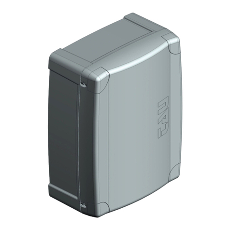
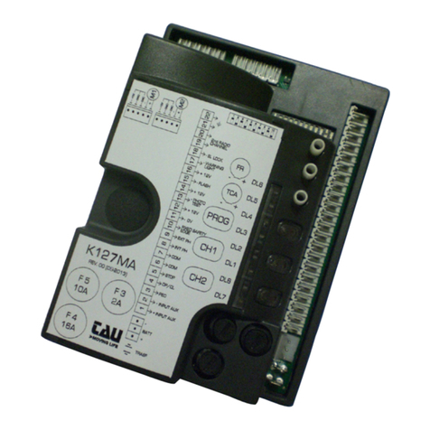
tau K101M Setup guide

1
Italiano
K101M
Quadro di comando per barriera automatica RBLO-E
IT - Istruzioni originali
TAU srl - Via Enrico Fermi, 43 - 36066 Sandrigo (VI) - Italy
Tel +39 0444 750190 - Fax +39 0444 750376
www.tauitalia.com
D_MNL0K101M 21-10-2020 - Rev.06
K101M
FR
SENS
TCA
F2
F1
7
6
5
8
9
10
11
12
13
14
1
2
3
Neutral
230 V AC
Power supply
Phase
M-OP
CLS
OLS
COM
FS1
FS2
M-COM
M-CL
4
RADIO
OP/CL
RESET
DL3
DL4
DL5
DL6
DL2
DL1
123456
123456
Flashing
light
230 V AC
max. 50W
Flashing
light
VLED DC
Open/Close
+
-
Stop
Antenna
Dip-switches
ON
M2
J4
SM
M3
DL3
DL4
DL5
DL6
DL2
DL1
PHOTO
CLOSE LIMIT SWITCH
OPEN LIMIT SWITCH
STOP
OPEN/CLOSE
RADIO CONTROLS
TCA
+-
SENS
+-
FR
+-
Photocells
Common
Photocell (N.C.)
RX
12345
TX
1 2
0 V AC
Photocell - 24 V AC

2
Introduzione
Attenzione: questo prodotto può essere installato solo da installatori professionisti. Solamente elettricisti qualicati e addestrati
possono eettuare i collegamenti, le programmazioni e la manutenzione di controllo.
Nessuna informazione contenuta nel presente fascicolo può essere considerata d’interesse per l’utilizzatore nale. Questo manuale è allegato
alla centralina K101M, non deve pertanto essere utilizzato per prodotti diversi!
Avvertenze importanti: Togliere l’alimentazione di rete alla scheda prima di accedervi.
La centralina K101M è destinata al comando di una barriera automatica.
Ogni altro uso è improprio e, quindi, vietato dalle normative vigenti.
Si consiglia di leggere attentamente tutte le istruzioni prima di procedere con l’installazione.
1. INSTALLAZIONE
Prima di procedere assicurarsi del buon funzionamento della parte meccanica e che l’asta sia stata correttamente bilanciata.
NB : si ricorda l’obbligo di mettere a massa l’impianto nonché di rispettare le normative sulla sicurezza in vigore in ciascun paese.
ATTENZIONE:
- non utilizzare cavi unilari (a conduttore unico), es. quelli citofonici, al ne di evitare interruzioni sulla linea e falsi contatti;
- non riutilizzare vecchi cavi preesistenti.
LA NON OSSERVANZA DELLE SOPRAELENCATE ISTRUZIONI PUÒ PREGIUDICARE IL BUON FUNZIONAMENTO DELL’APPARECCHIATURA E CREA-
RE PERICOLO PER LE PERSONE, PERTANTO LA “CASA COSTRUTTRICE” DECLINA OGNI RESPONSABILITÀ PER EVENTUALI MAL FUNZIONAMENTI
E DANNI DOVUTI ALLA LORO INOSSERVANZA.
2. SCHEDA DI COMANDO PER BARRIERA 230 V ac
• LOGICA CON MICROPROCESSORE
• STATO DEGLI INGRESSI VISUALIZZATO DA LEDs
• PROTEZIONE INGRESSO LINEA CON FUSIBILE
• CIRCUITO DI LAMPEGGIO INCORPORATO
• RADIO RICEVITORE 433,92 MHz INTEGRATO
• TEMPO DI LAVORO FISSO (max. 40 sec.)
• RILEVAMENTO AUTOMATICO DELLA FREQUENZA DI ALIMENTAZIONE (50 o 60 Hz)
• RALLENTAMENTO REGOLABILE
• COMPATIBILITÁ CON L’APP TAUOPEN E TAUAPP
ATTENZIONE:
- In caso di lunghi tratti di cavi ( > 20 m) per i comandi N.A. / N.C. (es: APRE/CHIUDE, STOP, PEDONALE, ecc), al ne di evitare malfun-
zionamenti del cancello si renderà necessario disaccoppiare i vari comandi mediante RELAYS oppure utilizzando il nostro disposi-
tivo 750T-RELE.
3. COLLAUDO
A collegamento ultimato:
• I Leds verdi devono essere tutti accesi (corrispondono ciascuno ad un ingresso Normalmente Chiuso). Si spengono solo quando sono
interessati i comandi ai quali sono associati.
• I Leds rossi dei comandi di apertura devono essere tutti spenti (corrispondono ciascuno ad un ingresso Normalmente Aperto) si accendono
solo quando sono interessati i comandi ai quali sono associati; il Led rosso DL1 deve essere acceso sso.
4. CARATTERISTICHE TECNICHE
Alimentazione scheda 230 V ac - 50-60 Hz
Potenza nominale 400 W
Fusibile rapido protezione alimentazione ingresso 230 V ac (F1 - 5x20) F 3,15 A
Tensione circuiti alimentazione motore 230 V ac
Tensione alimentazione circuiti dispositivi ausiliari 24 V ac
Fusibile rapido protezione ausiliari 24 V ac (F2 - 5x20) F 200 mA
Temperatura di funzionamento -20 °C ÷ +55 °C
5. LED DI DIAGNOSI
DL1 (RADIO CONTROLS) / ROSSO led di segnalazione ERRORI e programmazione RADIOCOMANDI
DL2 (OPEN/CLOSE) / ROSSO led di segnalazione pulsante APRE/CHIUDE
DL3 (PHOTO) / VERDE led di segnalazione FOTOCELLULA
DL4 (CLOSE LIMIT SWITCH) / VERDE led di segnalazione DI RALLENTAMENTO IN CHIUSURA
DL5 (OPEN LIMIT SWITCH) / VERDE led di segnalazione DI RALLENTAMENTO IN APERTURA
DL6 (STOP) / VERDE led di segnalazione pulsante STOP

3
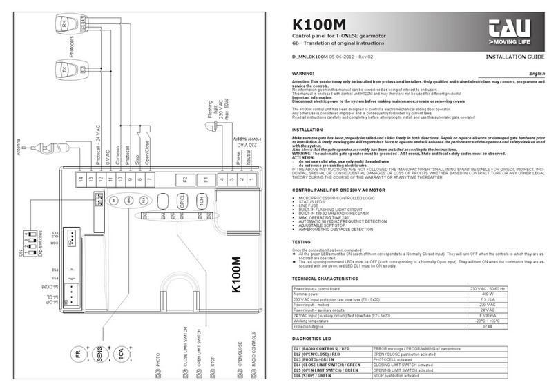
6. COLLEGAMENTI ALLA MORSETTIERA
Morsetti Funzione Descrizione
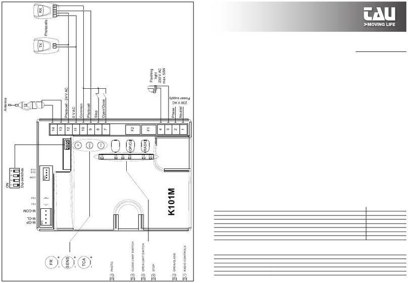
1 - 2 ALIMENTAZIONE ingresso ALIMENTAZIONE 230/115 V AC 50÷60Hz. 1= NEUTRO, 2= FASE;
3 - 4 LAMPEGGIANTE uscita LAMPEGGIANTE 230/115 VAC 50 W max. Il segnale fornito è già opportunamente modulato per l’uso
diretto. La frequenza di lampeggio è doppia in fase di chiusura; 3= 230 V AC, 4= 0 V ac;
5 - 6 LAMPEGGIANTE
LED
Uscita LAMPEGGIANTE LED 12 VDC uscita intermittente durante la manovra, la frequenza di lam-
peggio è doppia durante la chiusura.
7 - 10 APRE/CHIUDE ingresso pulsante APRE/CHIUDE (contatto Normalmente Aperto);
8 - 10 STOP ingresso pulsante STOP (contatto Normalmente Chiuso);
9 - 10 FOTOCELLULE
ingresso FOTOCELLULE O DISPOSITIVI DI SICUREZZA attivi in chiusura (contatto Normalmente Chiuso); il loro
intervento, in fase di chiusura provoca l’arresto seguito dalla totale riapertura dell’automazione, (10= Comune).
Nel caso di più dispositivi di sicurezza, collegare tutti i contatti NC IN SERIE.
11 - 12 FOTOCELLULE
24V AC
uscita 24 V ac 20 W per l’ALIMENTAZIONE DELLE FOTOCELLULE, RICEVITORI ESTERNI, etc; collegare max. n° 3
coppie di fotocellule. 11= 0 V AC, 12= 24 V ac;
13 - 14 ANTENNA Ingresso antenna per RX 433,92 MHz incorporata; 13= MASSA, 14= SEGNALE;
M2 MICRO SWITCH innesto rapido per connessione MICRO SWITCH (contatti Normalmente Chiusi). Arancio= Micro Switch rallenta-
mento in chiusura (CLS), rosso= Micro Switch rallentamento in aperura (OLS), grigio= Comune (COM);
FS1 - FS2 CONDESATORE faston per connessione CONDENSATORE di spunto del motore;
M3 MOTORE innesto rapido per connessione MOTORE monofase 230 V ac comune= BLU (M-COM); fase chiusura= MARRONE
(M-CL); fase apertura= NERO (M-OP).
J4 APP innesto rapido per connessione dispositivo per funzionamento APP (mod. T-WIFI / T-CONNECT).
SM SCHEDA
MEMORIA innesto rapido per connessione SCHEDA DI MEMORIA per codici radiocomandi.
7. REGOLAZIONI TRIMMER
FR. Regolazione coppia motore. Regolare il trimmer per una spinta dell’asta atta a garantirne il funzionamento. Ruotando il trimmer
in senso orario (+) si aumenta la coppia motore, viceversa, ruotandolo in senso antiorario (-), diminuisce.
SENS.
Permette di regolare la sensibilità della rilevazione dei necorsa meccanici. Ruotando il trimmer in senso orario (+) la rileva-
zione del fermo di battuta ne corsa sarà più sensibile. Viceversa ruotando in senso antiorario (-) diminuirà la sensibilità. Con
il trimmer nella posizione minima il motore rimarrà alimentato per il tempo totale impostato dal dip switch 6 nonostante
l’accostamento al necorsa meccanico avvenga precedentemente. È pertanto necessario regolarlo correttamente, per evitare
surriscaldamenti del motore.
T.C.A. Regolazione tempo di richiusura automatica da 1 a 120 secondi.
8. REGOLAZIONE FINECORSA
I microswitch dei necorsa gestiscono il rallentamento della barriera sia in chiusura che in apertura. Regolare quindi le camme dei necorsa
nel punto in cui si desidera che la barriera inizi la manovra di rallentamento sia in apertura che in chiusura.
9. DIP SWITCH
1CHIUSURA
AUTOMATICA
On ad apertura completata, la chiusura dell’automazione è automatica trascorso un tempo impostato sul trimmer T.C.A.;
O la chiusura necessita di un comando manuale;
22 / 4 TEMPI
On ad automazione funzionante, una sequenza di comandi di apertura/chiusura induce il cancello ad una APERTURA-
CHIUSURA-APERTURA-CHIUSURA, etc.;
O nelle stesse condizioni, la stessa sequenza di comandi di apertura/chiusura induce il cancello ad una APERTURA-
STOP-CHIUSURA-STOP-APERTURA-STOP, etc. (funzione passo-passo);
3NO REVERSE On l’automazione ignora i comandi di chiusura durante l’apertura.
O l’automazione si comporta come stabilito dal dip switch nr. 2.
4DIREZIONE
APERTURA
On funzionamento per anta con apertura verso sinistra;
O funzionamento per anta con apertura verso destra;
5NON UTILIZZATO O mantenere in OFF.
6T.L. RANGE On tempo di lavoro 8 sec. (per RBLO-LE)
O tempo di lavoro 4 sec. (per RBLO-E)
10. PROCEDURA DI IMPOSTAZIONE DELLA CORSA
Non è richiesta la memorizzazione della corsa perchè la centralina utilizza i tempi di lavoro. Con il dip switch n° 6 impostare il tempo di lavoro
desiderato in base alla tipologia della barriera utilizzata (RBLO-LE/RBLO-E).
Il motore verrà alimentato per tutta la durata del tempo impostato, indipendentemente dal raggiungimento dei necorsa meccanici.
Nel caso in cui il tempo impostato sia maggiore dell’eettivo tempo impiegato dall’automazione per aprire o chiudere si dovrà regolare il
Trimmer SENS in modo tale da permetterne la fermata anticipata una volta raggiunta il necorsa meccanico.

4
11. LED DI DIAGNOSI
LED - DL1
Il led, oltre ad indicare la programmazione dei radiocomandi, segnala eventuali errori con una serie di lampeggi predeniti:
sempre acceso: funzionamento regolare;
Lampeggio breve: mancato rilevamento automatico della frequenza di rete;
Contattare l’assistenza tecnica;
8 lampeggi: assenza segnale motore;
Controllare cablaggio, vericare che il motore giri liberamente;
L’indicazione di più errori viene eseguita con una pausa di 2 sec. tra una segnalazione e l’altra. L’indicazione degli errori persiste no all’esecu-
zione di una manovra completa (apertura e chiusura) dell’automazione.
12. FUNZIONI AVANZATE
Funzione orologio: è possibile utilizzare un timer (esempio settimanale) collegato all’ingresso del pulsante apre-chiude per mantenere aperta
l’automazione in determinate fascie orarie e permetterne poi la richiusura automatica.
N.B. I’automazione rimane aperta nchè l’ingresso Ap/Ch rimane impegnato (N.C.).
13. RADIO RICEVITORE 433,92 MHz INTEGRATO
Il radio ricevitore può apprendere no ad un max di 30 codici rolling code (S-2RP, S-4RP, K-SLIM-RP, T-4RP)
da impostare liberamente su tre canali.
Il primo canale comanda direttamente la scheda di comando per l’apertura dell’automazione; il secondo canale comanda un relè per un contatto
pulito N.A. in uscita ai morsetti nr 19 e 20 (max 24V AC, 1 A).
Il terzo canale comanda direttamente la scheda di comando per l’apertura pedonale dell’automazione.
APPRENDIMENTO RADIOCOMANDI
CH1 = 1° canale (APRE/CHIUDE) CH2 = 2° canale CH3 = 3° canale (PEDONALE)
1_ Premere brevemente il tasto CH1 se si desidera associare un radiocomando alla funzione APRE/CHIUDE;
2_ il led DL8 (verde) si accende sso per indicare la modalità di apprendimento dei codici (se non viene immesso nessun codice entro 10
secondi, la scheda esce dalla modalità di programmazione);
3_ premere il tasto del radiocomando che si desidera utilizzare;
4_ il led DL8 (verde) si spegne per segnalare l’avvenuta memorizzazione e si riaccende subito in attesa di altri radiocomandi (se ciò non accade,
provare a ritrasmettere oppure attendere 10 secondi e riprendere dal punto 1);
5_ se si desidera memorizzare altri radiocomandi, premere il tasto da memorizzare sugli altri dispositivi entro 2-3 sec. Passato questo lasso
di tempo (il led DL8 si spegne) è necessario ripetere la procedura dal punto 1 (no ad un massimo di 30 trasmettitori);
6_ se si desidera eettuare la memorizzazione sul 2° canale, ripetere la procedura dal punto 1 utilizzando il tasto CH2 anzichè il tasto CH1 (in
questo caso il led DL8 si accende con colore giallo);
7_ se si desidera eettuare la memorizzazione sul 3° canale, ripetere la procedura dal punto 1 utilizzando contemporaneamente i tasti CH1
e CH2 (in questo caso il led DL8 si accende con colore rosso);
8_ se si desidera uscire dalla modalità di apprendimento senza memorizzare un codice, premere brevemente il tasto CH1 o il tasto CH2.
Nel caso di raggiungimento del nr massimo di radiocomandi (nr 30), il led DL8 lampeggia velocemente per circa 3 secondi senza
però eseguire la memorizzazione.
PROGRAMMAZIONE REMOTA TRAMITE T-4RP e K-SLIM-RP / S-2RP / S-4RP (V 4.X)
Con la versione di software V 4.X è possibile eseguire l’apprendimento remoto con i radiocomandi T-4RP / K-SLIM-RP / S-2RP / S-4RP (V 4.X),
ossia senza agire direttamente sui tasti di programmazione della ricevente.
Sarà suciente disporre di un radiocomando già programmato nella ricevente per poter aprire la procedura di programmazione remota dei
nuovi radiocomandi. Seguire la procedura riportata sulle istruzioni del radiocomando T-4RP / K-SLIM-RP / S-2RP / S-4RP (V 4.X).
CANCELLAZIONE RADIOCOMANDI
1_ Tenere premuto per 3 secondi ca. il tasto CH1 al ne di cancellare tutti i radiocomandi ad esso associati;
2_ il led DL8 inizia a lampeggiare lentamente per indicare che la modalità di cancellazione è attivata;
3_ tenere premuto nuovamente il tasto CH1 per 3 secondi;
4_ il led DL8 si spegne per 3 secondi ca. per poi riaccendersi sso ad indicare l’avvenuta cancellazione;
5_ riprendere la procedura dal punto 1 utilizzando il tasto CH2 per cancellare tutti i radiocomandi ad esso associati;
6_ riprendere la procedura dal punto 1 utilizzando contemporaneamente i tasti CH1 e CH2 per cancellare tutti i radiocomandi associati al 3° canale;
7_ se si desidera uscire dalla modalità di cancellazione senza memorizzare un codice, premere brevemente il tasto CH1 o il tasto CH2.
MEMORIA CODICI
È possibile espandere la memoria dei codici da 30 * a 126, 254 o 1022, utilizzando le schede di memoria come indicato (innestandole nel con-
nettore J3, vedi schema cablaggio):
126 codici Art. 250SM126
254 codici Art. 250SM254
1022 codici Art. 250SM1022
* Le centrali, di serie, hanno una memoria di 30 codici. La scheda per la maggiorazione deve essere ordinata a parte.
Per permettere lo spostamento dei codici già precedentemente memorizzati nella centrale (max. 30) si renderà necessario installare una
scheda di memoria facendo attenzione che la centrale sia in quel momento spenta e che la scheda di memoria sia nuova di fabbrica e quindi
completamente vuota.
Una volta inserita la nuova scheda di memoria alla riaccensione della centrale i codici si sposteranno automaticamente nella stessa.
Lo spostamento dei codici da centrale a scheda di memoria non funziona nel caso in cui si utilizzi una scheda di memoria sulla quale
siano già stati memorizzati codici radiocomando e che sia stata cancellata succesivamente.
Per inserire nuovi radiocomandi si ripeterà l’operazione descritta precedentemente.
ATTENZIONE: nel momento in cui si innesta/toglie una scheda di memoria, la centrale deve essere spenta.

5
DICHIARAZIONE DI INCORPORAZIONE DEL COSTRUTTORE
(ai sensi della Direttiva Europea 2006/42/CE AlI. II.B)
Fabbricante: TAU S.r.l.
Indirizzo: Via E. Fermi, 43 - 36066 Sandrigo (Vi) - ITALIA
Dichiara sotto la propria responsabilità che il prodotto: Centrale di comando
realizzato per il movimento automatico di: Barriere stradali
per uso in ambiente: Generico completo di: Radioricevente
Modello: K101M Tipo:K101M
Numero di serie: vedi etichetta argentata Denominazione commerciale: Quadro di comando per barriere automatiche
È realizzato per essere incorporato su una chiusura (barriera automatica) o per essere assemblato con altri dispositivi al ne di movimentare una tale chiusura per
costituire una macchine ai sensi della Direttiva Macchine 2006/42/CE.
Dichiara inoltre che questo prodotto è conforme ai requisiti essenziali di sicurezza delle seguenti ulteriori direttive CEE:
- 2014/35/EU Direttiva Bassa Tensione - 2014/30/EU Direttiva Compatibilità Elettromagnetica
ed, ove richiesto, alla Direttiva:
- 2014/53/EU Apparecchiature Radio e apparecchiature terminali di telecomunicazione
Dichiara inoltre che non è consentito mettere in servizio il macchinario no a che la macchina in cui sarà incorporato o di cui diverrà componente sia stata
identicata e ne sia stata dichiarata la conformità alle condizioni della Direttiva 2006/42/CE.
Sono applicate le seguenti norme e speciche tecniche:
EN 61000-6-2; EN 61000-6-3; EN 60335-1; ETSI EN 301 489-1 V1.9.2; ETSI EN 301 489-3 V1.6.1; EN 300 220-2 V2.4.1; EN 12453:2000; EN 12445:2000; EN 60335-2-103.
Si impegna a trasmettere, su richiesta adeguatamente motivata delle autorità nazionali, informazioni pertinenti sulle quasi-macchine.
Sandrigo, 24/01/2018
Il Rappresentante Legale
_________________________________________
Loris Virgilio Danieli
Nome e indirizzo della persona autorizzata a costituire la documentazione tecnica pertinente:
Loris Virgilio Danieli - via E. Fermi, 43 - 36066 Sandrigo (Vi) Italia
RESET MEMORIA RADIO:
- tenere premuti i tasti CH1 e PROG no a che i led DL7 e DL8 iniziano a lampeggiare velocemente entrambi in giallo. A questo punto, rilasciare
i tasti e premerli nuovamente no a che i led si spengono, a conferma che l’operazione è terminata (se non vengono premuti e si resta in
attesa, la scheda ritorna in funzionamento normale dopo circa 12 secondi).
RESET DI FABBRICA:
- tenere premuti i tasti CH2 e PROG no a che i led DL7 e DL8 iniziano a lampeggiare velocemente entrambi in rosso. A questo punto, rila-
sciare i tasti e premerli nuovamente no a che i led si spengono (reset in corso), a conferma che l’operazione è terminata (se non vengono
premuti e si resta in attesa, la scheda ritorna in funzionamento normale dopo 12 secondi). Alla ripartenza, sarà necessario eseguire la
procedura di memorizzazione.
Eettuando un reset di fabbrica la memoria radio rimane invariata, pertanto i radiocomandi esistenti rimangono memorizzati.
14. PREDISPOSIZIONE AL FUNZIONAMENTO CON LE APPLICAZIONI TAU
Per poter utilizzare le applicazioni TauApp e TauOpen si renderà necessario collegare all’ingresso J4 della centrale mediante il cavo in dotazione
i rispettivi dispositivi T-WIFI e T-CONNECT.
Per attivare il funzionamento delle applicazioni vedere le rispettive istruzioni.
15. MALFUNZIONAMENTI: POSSIBILI CAUSE E RIMEDI
L’automazione non parte
a_ Vericare con lo strumento (Multimetro) la presenza dell’alimentazione 230V ac;
b_ Vericare che i contatti N.C. della scheda siano eettivamente normalmente chiusi (4 led verdi accesi) e che i led rossi dei comandi di
apertura siano spenti;
c_ Vericare che il led rosso DL1 sia acceso sso;
d_ Controllare con lo strumento (Multimetro) che i fusibili siano integri.
Il radiocomando ha poca portata
a_ Controllare che il collegamento della massa e del segnale dell’antenna non sia invertito;
b_ Non eseguire giunzioni per allungare il cavo dell’antenna;
c_ Non installare l’antenna in posizioni basse o in posizioni nascoste dalla muratura o dal pilastro;
d_ Controllare lo stato delle pile del radiocomando.
Il cancello si apre al contrario
a_ Invertire la posizione del di\p-switch nr. 4, dopo aver tolto l’alimentazione al quadro di comando.

6
English
K101M
Control panel for RBLO-E automatic barrier
GB - Translation of original instructions
TAU srl - Via Enrico Fermi, 43 - 36066 Sandrigo (VI) - Italy
Tel +39 0444 750190 - Fax +39 0444 750376
www.tauitalia.com
D_MNL0K101M 21-10-2020 - Rev.06
K101M
FR
SENS
TCA
F2
F1
7
6
5
8
9
10
11
12
13
14
1
2
3
Neutral
230 V AC
Power supply
Phase
M-OP
CLS
OLS
COM
FS1
FS2
M-COM
M-CL
4
RADIO
OP/CL
RESET
DL3
DL4
DL5
DL6
DL2
DL1
123456
123456
Flashing
light
230 V AC
max. 50W
Flashing
light
VLED DC
Open/Close
+
-
Stop
Antenna
Dip-switches
ON
M2
J4
SM
M3
DL3
DL4
DL5
DL6
DL2
DL1
PHOTO
CLOSE LIMIT SWITCH
OPEN LIMIT SWITCH
STOP
OPEN/CLOSE
RADIO CONTROLS
TCA
+-
SENS
+-
FR
+-
Photocells
Common
Photocell (N.C.)
RX
12345
TX
1 2
0 V AC
Photocell - 24 V AC

7
WARNING!
Attention: This product may only be installed from professional installers. Only qualied and trained electricians may connect,
programme and service the controls.
No information given in this manual can be considered as being of interest to end users.
This manual is enclosed with control unit K101M and may therefore not be used for dierent products!
Important information: Disconnect electric power to the system before making maintenance, repairs or removing covers
The K101M control unit has been designed to control an automatic barrier.
Any other use is considered improper and is consequently forbidden by current laws.
Read all instructions carefully and completely before attempting to install and use this automatic gate operator!
1. INSTALLATION
Make sure the gate has been properly installed and slides freely in both directions. Repair or replace all worn or damaged gate hardware
prior to installation. A freely moving gate will require less force to operate and will enhance the performance of the operator and safety
devices used with the system.
Also check that the gate operator assembly has been installed according to the instructions.
WARNING: The automatic barrier must be grounded - All Federal, State and local safety codes must be observed.
ATTENTION:
- do not use solid wire, use only multi threaded wire
- do not reuse pre-existing electric wire.
IF THE ABOVE INSTRUCTIONS ARE NOT FOLLOWED THE “MANUFACTURER” SHALL IN NO EVENT BE LIABLE FOR DIRECT, INDIRECT, INCIDENTAL,
SPECIAL OR CONSEQUENTIAL DAMAGES OR LOSS OF PROFITS WHETHER BASED IN CONTRACT TORT OR ANY OTHER LEGAL THEORY DURING
THE COURSE OF THE WARRANTY OR AT ANY TIME THEREAFTER.
2. CONTROL PANEL FOR 230 V ac BARRIER
•MICROPROCESSOR-CONTROLLED LOGIC
•STATUS LEDS
•LINE FUSE
•BUILT-IN FLASHING LIGHT CIRCUIT
• BUILT-IN 433.92 MHz RADIO RECEIVER
• MAX. OPERATING TIME 40”
• AUTOMATIC 50 / 60 HZ FREQUENCY DETECTION
•ADJUSTABLE SOFT-STOP
• COMPATIBILITY WITH OUR APPS: TAUOPEN AND TAUAPP
ATTENTION:
- In case of long sections of cables (> 20 m) for N.O./N.C. controls (e.g. OPEN / CLOSE, STOP, PEDESTRIAN, etc.), in order to avoid gate mal-
functions, it will be necessary to uncouple the various controls using RELAYS or using our 750T-RELE device.
3. TESTING
Once the connection has been completed:
• All the green LEDs must be ON (each of them corresponds to a Normally Closed input). They will turn OFF when the controls to which they
are associated are operated.
• The red opening command LEDs must be OFF (each corresponding to a Normally Open input). They will turn ON when the commands they
are associated with are given; red LED DL1 must be ON steadily.
4. TECHNICAL CHARACTERISTICS
Power input – control board 230 V ac - 50-60 Hz
Nominal power 400 W
230 V AC Input protection fast blow fuse (F1 - 5x20) F 3,15 A
Power input – motors 230 V ac
Power input – auxiliary circuits 24 V ac
24 V ac Input (auxiliary circuits) fast blow fuse (F2 - 5x20) F 500 mA
Working temperature -20°C ÷ +55°C
Protection degree IP 44
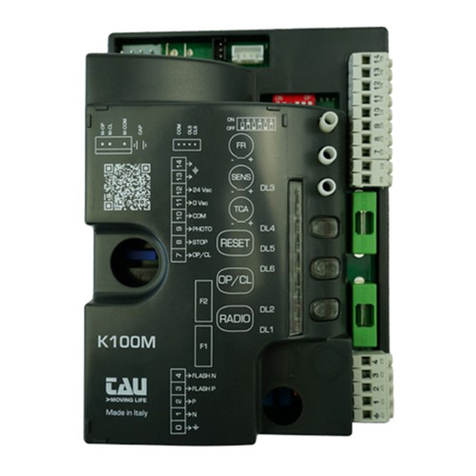
5. DIAGNOSTICS LED
DL1 (RADIO CONTROLS) / RED ERROR message / PROGRAMMING of transmitters
DL2 (OPEN/CLOSE) / RED OPEN / CLOSE pushbutton activated
DL3 (PHOTO) / GREEN PHOTOCELL activated
DL4 (CLOSE LIMIT SWITCH) / GREEN indicator led for the DECELERATION IN THE CLOSING maneuver
DL5 (OPEN LIMIT SWITCH) / GREEN indicator led for the DECELERATION IN THE OPENING maneuver
DL6 (STOP) / GREEN STOP pushbutton activated

8
6. TERMINAL BOARD CONNECTIONS
Terminals Function Description
1 + 2 POWER SUPPLY POWER input 230/115 V AC 50-60 Hz. 1= NEUTRAL 2= PHASE;
3 + 4 FLASHING LIGHT FLASHING LIGHT output 230/115 V AC, max. 50 W. The signal is already modulated for direct use; fast ashing
during closing, slow during opening. 3= 230/115 V AC, 4= 0 V AC;
5 - 6 LED
FLASHING LIGHT
FLASHING LIGHT Output FLASHING 12 VDC. Intermittent output during the operation, the ashing frequency is
doubled during closing;
7 + 10 OPEN/CLOSE OPEN/CLOSE input (Normally Open contact);
8 + 10 STOP STOP input (Normally Closed contact);
9 + 10 PHOTOCELLS
PHOTOCELLS OR SAFETY DEVICES input; active during closure (Normally Closed contact); the automation will
stop during closing and totally reopen it, (10= Common). If there is more than one safety device, connect all the
NC contacts IN SERIES.
11 + 12 24V AC
PHOTOCELLS 24 V AC 10 W output to Photocells, Receivers etc.; connect a up to 3 pair of photocells. 11= 0 V AC, 12= 24 V AC;
13 + 14 AERIAL 433,92 MHz built-in RX aerial input; 13= EARTH, 14= SIGNAL;
M2 MICRO SWITCH
Quick coupling for MICRO SWITCH connection (Normally Closed contacts). ORANGE= Micro Switch deceleration
in the closing maneuver (CLS), RED= Micro Switch Deceleration in the opening maneuver (OLS), GREY= Common
(COM);
FS1 + FS2 CAPACITOR CAPACITOR Terminals for motor start-up;
M3 MOTOR Quick coupling for 230 V AC single-phase MOTOR connection. BLUE= common (M-COM);
BROWN= closing (M-CL); BLACK= opening (M-OP).
J4 APP quick plug-in for device connection for APP operation (mod. T-WIFI / T- CONNECT)
SM MEMORY CARD quick plug-in for MEMORY CARD connection for transmitters codes.
7. TRIMMER ADJUSTMENTS
FR.
Motor torque adjustment. Turning the trimmer clockwise (+) the torque will be increased; Turning the trimmer counterclockwise (-)
the torque will be decreased.
Note: The trimmer is set to provide sucient thrust to work the automation within the limits established by current
standards (EN 12453).
SENS.
It allows you to adjust the detection sensitivity of the mechanical limit switches. By turning the trimmer clockwise (+) the detec-
tion of the limit stop will be more sensitive. On the contrary, by turning counterclockwise (-) the sensibility will decrease. With
the trimmer in the minimum position, the motor will remain powered for the total time set by the dip switch n° 6 even though
the mechanical limit switch has been already reached. It is therefore necessary to adjust it correctly to avoid motor overheating.
T.C.A.
Automatic closing time adjustment. Turning the trimmer clockwise (+) time will be increased; Turning the trimmer counterclockwise
(-) the time will be decreased.
Note: The time values can be set between 1 and 120 seconds.
8. LIMIT SWITCH ADJUSTMENT
The microswitches control the deceleration of the barrier both during closing and opening maneuvers. Adjust the limit switch cams at the point
where you want the barrier to start the deceleration in both opening and closing maneuvers.
9. DIP SWITCH
1AUTOMATIC
CLOSING
On automatic closing enabled.
O automatic closing disabled.
22 / 4 STROKE
On (with Automatic closing enabled) Two-Stroke operation mode OPEN-CLOSE, OPEN-CLOSE, etc.
O (with Automatic closing enabled) Four-Stroke operation mode OPEN-STOP-CLOSE-STOP, OPEN-STOP-CLOSE-
STOP, etc.
3NO REVERSE On the automation ignores the close command while it is opening (NO REVERSE);
O the automation behaves according to the position of dip-switch n° 2;
4OPENING
DIRECTION
On Left-hand leaf opening mode;
O Right-hand leaf opening mode;
5NOT USED O keep it in the OFF position
6OPERATING RANGE On 8 seconds for RBLO-LE
O 4 seconds for RBLO-E
10. SETUP STROKE PROCEDURE
It is not required to memorize the stroke because the control unit uses the working times. With the dip switch n° 6 set the desired working time
based on the type of the barrier used (RBLO-LE/ RBLO-E).
The motor will be powered for the entire duration of the set time, regardless of whether the mechanical limit switches have been reached.
If the set time is higher than the actual time taken by the automation to open or to close you will have to adjust the Trimmer SENS so you can
allow an early stop once the mechanical limit switch has been reached.

9
11. DIAGNOSIS LED
DL1 LED
Other than indicating the programming of a transmitter is going on, DL1 LED advises error messages as follows:
Steady light: Normal operation;
Slow ashing: Automatic 50 / 60 HZ Frequency Detection Error;
Contact Technical Service;
8 ashes: No motor signal;
Check wiring - Make sure the motor can rotate freely;
Multiple errors are indicated by a 2” pause between error messages. Messages will be shown until a complete opening/closing cycle is performed.
12. ADVANCED FUNCTIONS
Clock function: a timer can be connected to the open-close pushbutton in order to keep the automation open at certain times during the day,
after which it reverts to automatic closing.
Note: The automation remains open as long as the OP/CL input continues to be activated.
13. 433.92 MHz BUILT-IN RADIO RECEIVER
The radio receiver can learn up to a maximum of 30 codes of rolling code (S2RP, S4RP, K-SLIM-RP, T-4RP) to be set freely on 3 channels.
The rst channel directly commands the control board for opening the automatic device; the second channel commands a relay for a N.O. no-
voltage output contact (terminals 19 - 20, max. 24V AC, 1 A) and the third channel controls directly the pedestrian opening from the controller.
LEARNING SYSTEM FOR RADIO CONTROL DEVICES
CH1 = 1st channel (OPEN/CLOSE) CH2 = 2nd channel CH3 = 3rd channel (PEDESTRIAN)
1_ Press button CH1 briey to associate a radio control device with the OPEN/CLOSE function;
2_ the (green) DL8 LED is ON to indicate the code learni ng mode has been activated (if no code is entered within 10 seconds the board exits
the programming function);
3_ press the button of the relative radio control device;
4_ the (green) DL8 LED turns o to indicate saving is complete and then on again immediately waiting for other radio control devices (if this
is not the case, try to re-transmit or wait 10 seconds and restart from point 1);
5_ to memorise codes to other radio control devices, press the key to be stored on other devices within 2-3 sec. After this time (DL8 LED turns
o) must repeat the procedure from point 1 (up to a maximum of 30 transmitters);
6_ if you wish to save on the 2nd channel, repeat the procedure from point 1 using the CH2 key instead of CH1 (in this case the DL8 LED is yellow);
7_ to program transmitters into the third channel, repeat procedure from point 1 using CH1 and CH2 buttons at the same time (DL8 will turn on red);
8_ to exit the learning mode without memorising a code, press button CH1 or CH2 briey.
If the maximum number of radio controls is reached (30), the LED DL8 will begin to ash rapidly for about 3 seconds but with-
out performing memorisation.
REMOTE PROGRAMMING BY MEANS OF T-4RP / K-SLIM-RP / S-2RP / S-4RP (V 4.X)
With the new version of software V 4.X it is possible to carry out the remote self-learning of the new version of transmitters T-4RP / K-SLIM-RP
/ S-2RP / S-4RP (V 4.X), that is without pressing the receiver’s programming buttons.
It will be sucient to have an already programmed transmitter in the receiver in order to start the procedure of remote programming of the
new transmitters. Follow the procedure written on the instructions of the transmitter T-4RP / K-SLIM-RP / S-2RP / S-4RP (V 4.X).
CANCELLING CODES FROM RADIO CONTROL DEVICES
1_ Keep button CH1 pressed for 3 seconds in order to cancel all the associated radio control devices;
2_ LED DL8 ashes slowly to indicate that the cancellation mode has been activated;
3_ press button CH1 again for 3 seconds;
4_ LED DL8 turns o for approx. 3 seconds and then remains steady to indicate that the code has been cancelled;
5_ repeat the procedure from point 1 using button CH2 to cancel all the associated radio control devices;
6_ repeat procedure from point 1 using CH1 and CH2 buttons at the same time to erase all transmitters programmed into the third channel;
7_ to exit the learning mode without memorising a code, press button CH1 or CH2 briey.
MEMORY CAPACITY
The code memory capacity* of the control unit can be expanded from 30 to 126, 254 or 1022 codes (transmitters) by replacing the memory cards as
follows
(plug them onto J3 connector, see wiring diagram)
:
126 codes Art. 250SM126
254 codes Art. 250SM254
1022 codes Art. 250SM1022
* Control units are supplied with a standard built-in 30-code memory. The memory card for enhancing the code memory capacity must be ordered
separately.
To allow the previously stored codes (max. 30) to be moved to the control unit, it is required to install a memory card, making sure that the
control unit is at that time o and that the memory card is brand new and therefore completely empty.
When the control unit is restarted, the codes will automatically move to the memory card.
Moving the codes from the control unit to the memory card does not work if on the memory card used, radio control codes have already been
stored and the memory card has been subsequently erased.
To insert new radio controls, the operation described above shall be repeated.
WARNING: Control unit must be turned OFF to insert / remove a memory card.
RADIO MEMORY RESET:
- press without releasing keys CH1 and PROG till LEDs DL7 and DL8 start ashing quickly with a yellow light. At this point release the keys and
press them again till the LEDs go o conrming the operation is complete (if they are not pressed the board reverts to normal operation
after about 12 seconds).

10
HARD RESET (factory setting):
- press without releasing keys CH2 and PROG till LEDs DL7 and DL8 start ashing quickly with a red light. At this point release the keys and
press them again till the LEDs go o (reset in progress), conrming the operation is complete (if they are not pressed the board reverts to
normal operation after about 12 seconds); When the unit starts again saving will be required.
In case of Hard Reset the memory of the radio receiver will not be erased: all existing
transmitters remain programmed.
14. SET-UP FOR OPERATION WITH TAU APPS
In order to use the TauApp and TauOpen apps, it will be necessary to connect to input J4 of the control unit using the supplied cable, the re-
spective T-WIFI and T-CONNECT devices. To activate the operation of the apps see the respective instructions.
15. TROUBLESHOOTING GUIDE
Operator does not run
a- Check 230/115 V power supply with a voltmeter;
b- Check that all 4 green LEDs (Normally Closed contacts, DL3, DL4, DL5 and DL6) are ON, and that all two red LEDs (Normally Open con-
tacts, DL1 and DL2) are OFF;
c- Check that the red DL1 LED is ON;
d- Check that the fuses are intact with a voltmeter.
The radio control has little range
a- Check that the ground and the aerial signal connections have not been inverted;
b- Do not make joints to increase the length of the aerial wire;
c- Do not install the aerial in a low position or behind walls or pillars;
d- Check the state of the transmitter’s batteries.
The gate opens the wrong way
a_ Invert the position of DIP 4 (after having turned o the power to the control unit).
MANUFACTURER’S DECLARATION OF INCORPORATION
(in accordance with European Directive 2006/42/EC App. II.B)
Manufacturer: TAU S.r.l.
Address: Via E. Fermi, 43 - 36066 Sandrigo (Vi) ITALY
Declares under its sole responsibility, that the product: Electronic control unit
designed for automatic movement of: Road barriers
for use in a: General environment
complete with: Radioreceiver
Model: K101M
Type: K101M
Serial number: see silver label
Commercial name: Control panel for automatic barriers
Has been produced for incorporation on an access point (automatic barrier) of for assembly with other devices used to move such an access point, to constitute
a machine in accordance with the Machinery Directive 2006/42/EC.
Also declares that this product complies with the essential safety requirements of the following EEC directives:
- 2014/35/EU Low Voltage Directive
- 2014/30/EU Electromagnetic Compatibility Directive
and, where required, with the Directive:
- 2014/53/EU Radio equipment and telecommunications terminal equipment
Also declares that it is not permitted to start up the machine until the machine in which it is incorporated or of which it will be a component has been identied
with the relative declaration of conformity with the provisions of Directive 2006/42/EC.
The following standards and technical specications are applied:
EN 61000-6-2; EN 61000-6-3; EN 60335-1; ETSI EN 301 489-1 V1.9.2; ETSI EN 301 489-3 V1.6.1; EN 300 220-2 V2.4.1; EN 12453:2000; EN 12445:2000; EN 60335-2-103.
The manufacturer undertakes to provide, on sufciently motivated request by national authorities, all information pertinent to the quasi-machinery.
Sandrigo, 24/01/2018 Legal Representative
_________________________________________
Loris Virgilio Danieli
Name and address of person authorised to draw up all pertinent technical documentation:
Loris Virgilio Danieli - via E. Fermi, 43 - 36066 Sandrigo (Vi) Italy

11

Via Enrico Fermi, 43 - 36066 Sandrigo (VI) - Italy
Tel +39 0444 750190 - Fax +39 0444 750376
[email protected] - www.tauitalia.com
Other manuals for K101M
1
This manual suits for next models
1
Table of contents
Languages:
Other tau Control Panel manuals
