DKS Series 6050 User manual

Series 6050 and 6100
Installation/Owner’s Manual
Copyright 2009 DoorKing, Inc.All rights reserved.
TM
Copyright 2011 DoorKing, Inc.All rights reserved.
Date Installed:
Installer/Company Name:
Phone Number:
Leave Manual with Owner
Vehicular Swing Gate Operator
UL 325 Compliant
Circuit Board
Serial Number
and Revision Letter:
Series 6050 and 6100
WARNING
MOVINGGATECANCAUSE
Operategateonlywhengateareaisinsight
andfreeofpeopleandobstructions.
Donotallowchildrentoplayingatearea
oroperategate.
Donotstandingatepathorwalkthrough
pathwhilegateismoving.
Readowner’smanualandsafety instructions.
SERIOUSINJURYORDEATH
CLASS
CERTIFIEDTO
CAN/CSAC22.2NO.247
CONFORMSTO
ANSI/UL-325
VEHICULARGATEOPERATOR
HP
53382
MODEL
SERIAL
VOLTSPHASE
AMPS60Hz
MAXGATELOAD
DoorKing,Inc.,Inglewood,CA
Pad Mount
Post Mount
Use this manual for circuit board 4502-010 Revision K or higher.
For operators manufactured July 2011and later.
6050-065-V-7-11


6050-065-V-7-11 1
UL325 Class of Operation Model 6050 Class I Only ; Model 6100 Class I, II, III, IV
Type of Gate Vehicular Swing Gates Only
Entrapment Protection Primary - Inherent adjustable clutch (Type C)
Secondary - Inherent entrapment protection system (Type A) and provision
for connection of a non-contact sensor (Type B1)
6050 / 6100 SPECIFICATIONS
DoorKing, Inc. reserves the right to make changes in the products described in this manual without notice and without obligation of DoorKing, Inc. to notify any
persons of any such revisions or changes. Additionally, DoorKing, Inc. makes no representations or warranties with respect to this manual. This manual is
copyrighted, all rights reserved. No portion of this manual may be copied, reproduced, translated, or reduced to any electronic medium without prior written
consent from DoorKing, Inc.
11”
27.75” with Convenience Open
23” Standard
Post Mount Kit
P/N 2600-674
Pad Mount Kit
P/N 2600-671
Arm Assembly
6050
Arm Assembly
Distance can vary.
6” minimum.
10.5”
13.5”
6.75”
6.25” 7.25”
6.75”
2.25”
18”
5”
5”
11”
Note: 6100’s with Convenience Open:
Output shaft is offset 1” from center.
9.5”
11”
6”
Model # Max Gate
Weight
Max Gate
Length
Horsepower - Volts
1/2 HP - 115 VAC
1/2 HP - 115 VAC
1/2 HP - 115 VAC
1/2 HP - 115 VAC
1/2 HP - 115 VAC
1/2 HP - 115 VAC
Standard
Standard
Standard
Standard
With Convenience Open
6050-080
6050-081
6100-080
6100-081
6100-082
6100-083
400 Lbs.
400 Lbs.
500 Lbs.
500 Lbs.
500 Lbs.
500 Lbs.
Type
Operator
Primary
Secondary
Primary
Secondary
Primary
Secondary
10 Ft.
10 Ft.
14 Ft.
14 Ft.
14 Ft.
14 Ft.
Cycles Per
Hour
10
10
60
60
60
60
Speed
90°
12-14 Sec
12-14 Sec
12-14 Sec
12-14 Sec
12-14 Sec
12-14 Sec
AmpOperator Cover Type
4.3
4.3
5.4
5.4
5.4
5.4
Convenience
Open
No
No
No
No
Yes
Yes
Dimensions are the same as shown
above for the operator covers.
Operator Covers
6100
Use this manual for the Model 6050/6100 operators with circuit board 4502-010 Rev K or higher ONLY.
For operators manufactured July 2011 and later.

6050-065-V-7-11
2
TABLE OF CONTENTS
SPECIFICATIONS 1
ASTM F2200 Standard for Gate Construction
Important Safety Instructions
Instructions regarding intended installation:
Important Notices
UL 325 Entrapment Protection
Glossary
Swing Gate Requirements
Swing Gate Protection
4
4
4
5
6
7
8
9
SECTION 1 - INSTALLATION 10
10
10
11-12
13
13
14
14
14
15
1.1 Operator Position
1.2 Post Mount or Pad Mount Base Assembly
1.3 Underground Conduit Requirements
1.4 Pad Mount
1.5 Post Mount
1.6 Arm and Gate Bracket Installation
1.7 Manually Adjust the Open and Closed Gate Positions
1.8 Installation of Warning Signs
1.9 Gates Opening Wider Than 90°
SECTION 2 - AC POWER TO OPERATOR(S) 16
16
16
17
2.1 High Voltage Wire Runs
2.2 High Voltage Terminal Connection
2.3 Bi-Parting Gates Wiring - Dual Gate Operators
SECTION 3 - ADJUSTMENTS 18
18
19
20
21
22
22
3.1 4502 Circuit Board Description and Adjustments
3.2 DIP-Switch SW 1 Settings
3.3 DIP-Switch SW 2 Settings
3.4 Automatic Open / Close Limit Adjustment
3.5 Clutch Adjustment
3.6 Inherent Entrapment Protection System

6050-065-V-7-11 3
TABLE OF CONTENTS
SECTION 8 - MAINTENANCE AND TROUBLESHOOTING 35
8.1 Maintenance
8.2 Troubleshooting
8.3 Accessory Items
Model 6050/6100 Wiring Diagrams
35
36-37
38
39-42
SECTION 6 - OPERATING INSTRUCTIONS 28
6.1 Power and Reset Switches
6.2 Shutdown Conditions
Soft Shutdown
Hard Shutdown
6.3 Manual Gate Operation
Emergency Vehicle Access Conditions
FAIL-SAFE Manual Operation
Manual Release
31-32
28
29-30
SECTION 7 - OPTIONAL CONVENIENCE OPEN SYSTEM
7.1 Circuit Board 2340 Setup
7.2 DC System Description
7.3 DIP-Switch Settings
33
34
34
33
SECTION 4 - ENTRAPMENT AND SAFETY PROTECTION
4.1 Main and Auxiliary Terminal Descriptions
4.2 Entrapment and Safety Device Locations
4.3 Loop Detector Wiring
23
24
25
23
SECTION 5 - CIRCUIT BOARD WIRING
5.1 Main Terminal Description
5.2 Control Wiring
5.3 Auxiliary Terminal Description
5.4 Auxiliary Terminal Wiring
26
27
28
28
26

6050-065-V-7-11
4
Instructions regarding intended installation:
Vehicular gates should be constructed and installed in accordance with ASTM F2200; Standard Specification for Automated
Vehicular Gate Construction. For a copy of this standard, contact ASTM directly at 610-832-9585; [email protected]; or
www.astm.org.
Important Safety Instructions
WARNING - To reduce the risk of injury or death:
1. READ AND FOLLOW ALL INSTRUCTIONS.
2. Never let children operate or play with gate controls. Keep the remote control away from children.
3. Always keep people and objects away from gate. NO ONE SHOULD CROSS THE PATH OF THE MOVING GATE.
4. Test the operator monthly. The gate MUST reverse on contact with a rigid object or stop or reverse when an object
activates the non-contact sensors. After adjusting the force or the limit of travel, retest the gate operator. Failure to adjust
and retest the gate operator properly can increase the risk of injury or death.
5. Use the emergency release only when the gate is not moving.
6. KEEP GATES PROPERLY MAINTAINED. Read the owner's manual. Have a qualified service person make repairs to gate
hardware.
7. The entrance is for vehicles only. Pedestrians must use separate entrance.
8. SAVE THESE INSTRUCTIONS!
•Install the gate operator only if:
1. The operator is appropriate for the construction of the gate and the usage class of the gate.
2. All openings of a horizontal slide gate are guarded or screened from the bottom of the gate to a minimum of 6 feet
(1.83 m) above the ground to prevent a 2 ¼ inch (57.2 mm) diameter sphere from passing through the openings
anywhere in the gate, and in that portion of the adjacent fence that the gate covers in the open position.
3. All exposed pinch points are eliminated or guarded.
4. Guarding is supplied for exposed rollers.
•The operator is intended for installation only on gates used for vehicles. Pedestrians must be supplied with a separate
access opening. The pedestrian access opening shall be designed to promote pedestrian usage. Locate the gate such that
persons will not come in contact with the vehicular gate during the entire path of travel of the vehicular gate.
•The gate must be installed in a location so that enough clearance is supplied between the gate and adjacent structures
when opening and closing to reduce the risk of entrapment. Swinging gates should not open into public access areas.
•The gate must be properly installed and work freely in both directions prior to the installation of the gate operator. Do not
over-tighten the operator clutch, pressure relief valve or reduce reversing sensitivity to compensate for a damaged gate.
•For gate operators utilizing Type D protection:
1. The gate operator controls must be placed so that the user has full view of the gate area when the gate is moving.
2. A warning placard shall be placed adjacent to the controls.
3. An automatic closing device (such as a timer, loop sensor, or similar device) shall not be employed.
4. No other activation device shall be connected.
•Controls intended for user activation must be located at least ten feet (10’) away from any moving part of the gate and
where the user is prevented from reaching over, under, around or through the gate to operate the controls. Outdoor or
easily accessible controls should have a security feature to prevent unauthorized use.
•The Stop and/or Reset button must be located in the line-of-sight of the gate. Activation of the reset control shall not
cause the operator to start.
•A minimum of two (2) WARNING SIGNS shall be installed, one on each side of the gate where easily visible.
•For gate operators utilizing a non-contact sensor:
1. See the instructions on the placement of non-contact sensors for each type of application.
2. Care shall be exercised to reduce the risk of nuisance tripping, such as when a vehicle trips the sensor while the gate
is still moving in the opening direction.
3. One or more non-contact sensors shall be located where the risk of entrapment or obstruction exist, such as the
perimeter reachable by a moving gate or barrier.
ASTM F2200 Standard for Gate Construction

6050-065-V-7-11 5
•For gate operators utilizing contact sensors:
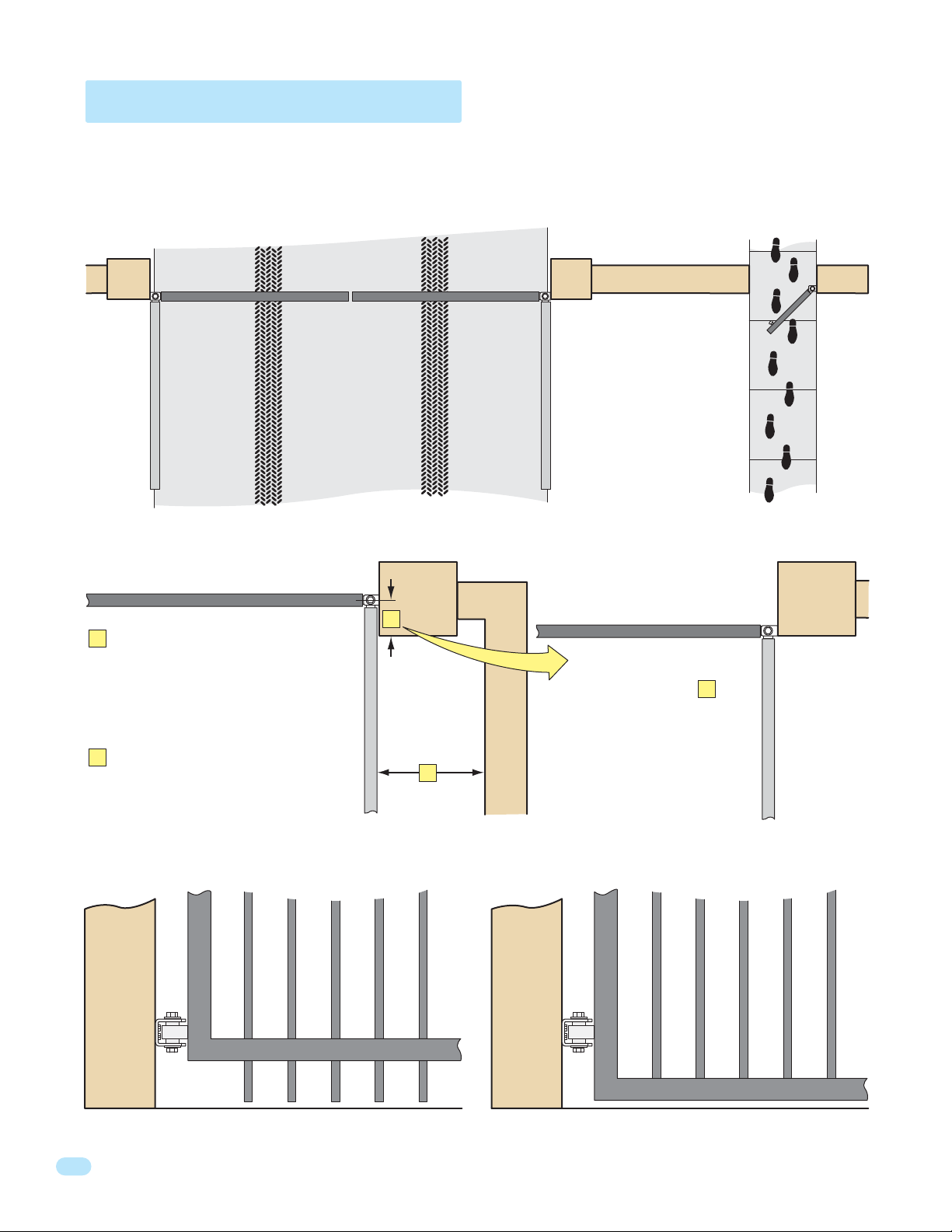
1. One or more contact sensors shall be located where the risk of entrapment or obstruction exist, such as at the
leading edge, trailing edge, and post mounted both inside and outside of a vehicular horizontal slide gate.
2. One or more contact sensors shall be located at the bottom edge of a vehicular vertical lift gate.
3. One or more contact sensors shall be located at the pinch point of a vehicular vertical pivot gate.
4. A hardwired contact sensor shall be located and its wiring arranged so that the communication between the sensor
and the gate operator is not subjected to mechanical damage.
5. A wireless contact sensor such as one that transmits radio frequency (RF) signals to the gate operator for
entrapment protection functions shall be located where the transmission of the signals are not obstructed or
impeded by building structures, natural landscaping or similar obstructions. A wireless contact sensor shall function
under the intended end-use conditions.
6. One or more contact sensors shall be located at the bottom edge of a vertical barrier (arm).
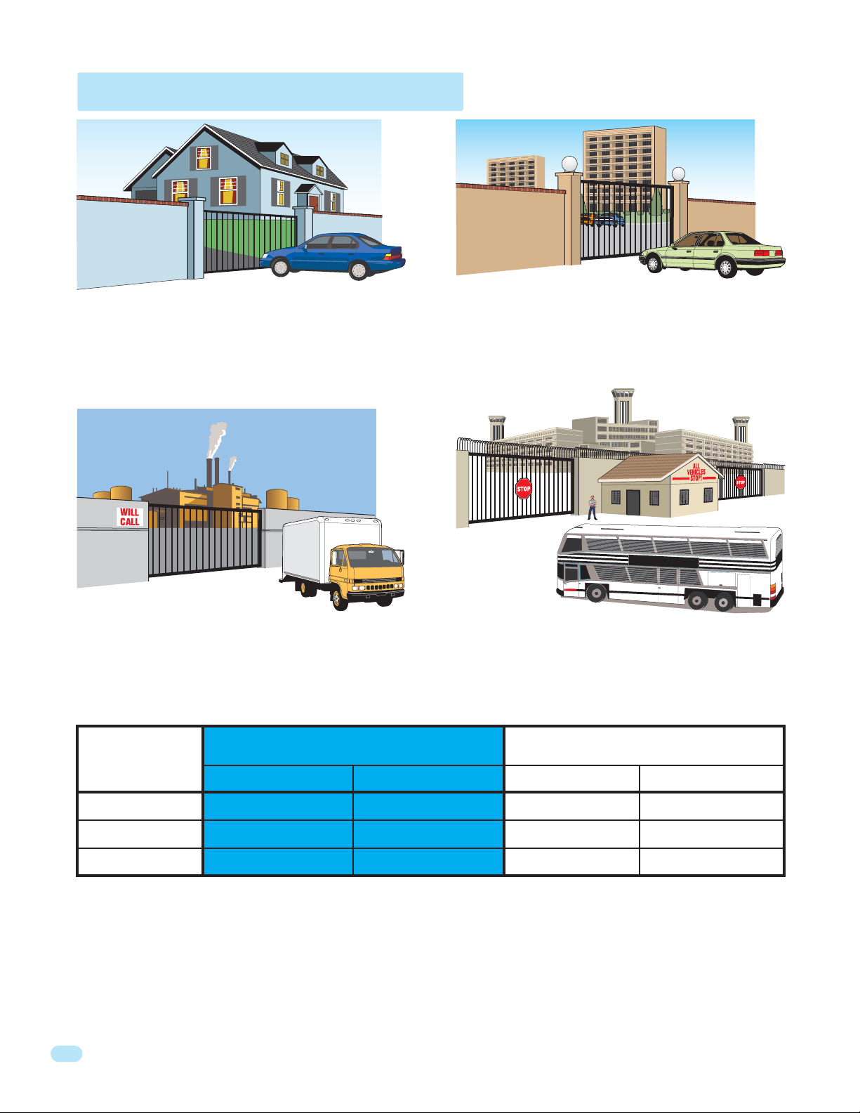
Vehicular gate operator products provide convenience and security. However, gate operators must use high levels of force
to move gates and most people underestimate the power of these systems and do not realize the potential hazards associ-
ated with an incorrectly designed or installed system. These hazards may include:
•Pinch points
•Entrapment areas
•Reach through hazards
•Absence of entrapment protection devices
•Improperly located access controls
•Absence of vehicle protection devices
•Absence of controlled pedestrian access
In addition to these potential hazards, automated vehicular gate systems must be installed in accordance with the UL-325
Safety Standard and the ASTM F2200 Construction Standard. Most lay persons are unaware of, or are not familiar with,
these standards. If an automated vehicular gate system is not properly designed, installed, used and maintained, serious
injuries or death can result. Be sure that the installer has instructed you on the proper operation of the gate and gate
operator system.
Be sure that the installer has trained you about the basic functions of the required reversing systems associated with your
gate operating system and how to test them. These include reversing loops, inherent reversing system, electric edges,
photoelectric cells, or other external devices.
•This Owner’s Manual is your property. Keep it in a safe place for future reference.
•Be sure that all access control devices are installed a minimum distance of 10 feet away from the gate and gate
operator, or in such a way that a person cannot touch the gate or gate operator while using the device. If access
control devices are installed in violation of these restrictions, immediately remove the gate operator from service
and contact your installing dealer.
•Loops and loop detectors, photo-cells or other equivalent devices must be installed to prevent the gate from
closing on vehicular traffic.
•The speed limit for vehicular traffic through the gate area is 5 MPH. Install speed bumps and signs to keep
vehicular traffic from speeding through the gate area. Failure to adhere to posted speed limits can result in
damage to the gate, gate operator, and to the vehicle.
•Be sure that all persons who will use the gate system are familiar with the proper use of the gate and gate
operator and are familiar with the possible hazards associated with the gate system.
•Be sure that warning signs are permanently installed on both sides of the gate in an area where they are fully
visible to traffic.
•It is your responsibility to periodically check all entrapment protection devices. If any of these devices are
observed to function improperly, remove the operator from service immediately and contact your installing or
servicing dealer.
•Follow the recommended maintenance schedule.
•Do not allow children to play in the area of the operator or to play with any gate-operating device.
•To remove the gate operator from service, operate the gate to the full open position and then shut off power to
the operator at the service panel.
Important Notices

6050-065-V-7-11
6
UL 325 Entrapment Protection
Class I
Class I and II
Class III
Class IV
Class II
Class III Class IV
A vehicular gate operator (or system) intended for use in a
home of one-to four single family dwelling, or a garage or
parking area associated therewith.
A vehicular gate operator (or system) intended for use in a
commercial location or building such as a multi-family
housing unit (five or more single family units) hotel,
garages, retail store or other building servicing the general
public.
A vehicular gate operator (or system) intended for use in a
industrial location or building such as a factory or loading
dock area or other locations not intended to service the
general public.
A vehicular gate operator (or system) intended for use in a
guarded industrial location or building such as an airport
security area or other restricted access locations not
servicing the general public, in which unauthorized access
is prevented via supervision by security personnel.
This table illustrates the entrapment protection requirements for each of the four UL 325 classes.
A- Inherent entrapment protection system.
B1 - Provision for connection of, or supplied with, a non-contact sensor (photoelectric sensor or the equivalent).
When used as the PRIMARY device, must be monitored.
B2 - Provision for connection of, or supplied with, a contact sensor (edge device or the equivalent).
When used as the PRIMARY device, must be monitored.
C- Inherent adjustable clutch or pressure relief device.
D- Provision for connection of, or supplied with, an actuating device requiring continuous pressure to maintain
opening or closing motion of the gate.
E- An inherent audio alarm.
STATE PRISON
UL 325
Classifications
Horizontal Slide, Vertical Lift, Vertical Pivot Swing and Vertical Barrier (arm)
Primary Protection
A B1, B2 or D A, B1, B2, C or DA or C
A, B1 or B2 A, B1, B2, D or E A, B1, B2, C or DA, B1, B2 or C
A, B1, B2 or D A, B1, B2, D or E A, B1, B2, C, D or EA, B1, B2, C or D
Secondary Protection Primary Protection Secondary Protection

6050-065-V-7-11 7
Glossary
GATE - A moving barrier such as a swinging, sliding, raising, lowering, or the like, barrier, that is a stand-alone passage
barrier or is that portion of a wall or fence system that controls entrance and/or egress by persons or vehicles and
completes the perimeter of a defined area.
RESIDENTIAL VEHICULAR GATE OPERATOR – CLASS I - A vehicular gate operator (or system) intended for use in a home
of one-to four single family dwelling, or garage or parking area associated therewith.
COMMERCIAL / GENERAL ACCESS VEHICULAR GATE OPERATOR - CLASS II - A vehicular gate operator (or system)
intended for use in a commercial location or building such as a multi-family housing unit (five or more single family units),
hotels, garages, retail store, or other building servicing the general public.
INDUSTRIAL / LIMITED ACCESS VEHICULAR GATE OPERATOR - CLASS III - A vehicular gate operator (or system)
intended for use in an industrial location or building such as a factory or loading dock area or other locations not intended
to service the general public.
RESTRICTED ACCESS VEHICULAR GATE OPERATOR - CLASS IV - A vehicular gate operator (or system) intended for use in
a guarded industrial location or building such as an airport security area or other restricted access locations not servicing
the general public, in which unauthorized access is prevented via supervision by security personnel.
VEHICULAR BARRIER (ARM) OPERATOR (OR SYSTEM) - An operator (or system) that controls a cantilever type device (or
system), consisting of a mechanical arm or barrier that moves in a vertical arc, intended for vehicular traffic flow at
entrances or exits to areas such as parking garages, lots or toll areas.
VEHICULAR HORIZONTAL SLIDE-GATE OPERATOR (OR SYSTEM) - A vehicular gate operator (or system) that controls a
gate which slides in a horizontal direction that is intended for use for vehicular entrance and exit to a drive, parking lot, or
the like.
VEHICULAR SWING-GATE OPERATOR (OR SYSTEM) - A vehicular gate operator (or system) that controls a gate which
moves in an arc in a horizontal plane that is intended for use for vehicular entrance and exit to a drive, parking lot, or the
like.
SYSTEM - In the context of these requirements, a system refers to a group of interacting devices intended to perform a
common function.
WIRED CONTROL - A control implemented in a form of fixed physical interconnections between the control, the associated
devices, and an operator to perform predetermined functions in response to input signals.
WIRELESS CONTROL - A control implemented in means other than fixed physical interconnections (such as radio waves or
infrared beams) between the control, the associated devices, and an operator to perform predetermined functions in
response to input signals.
INHERENT ENTRAPMENT PROTECTION SYSTEM - A system, examples being a motor current or speed sensing system,
which provides protection against entrapment upon sensing an object and is incorporated as a permanent and integral part
of the operator.
EXTERNAL ENTRAPMENT PROTECTION DEVICE - A device, examples being an edge sensor, a photoelectric sensor, or
similar entrapment protection device, which provides protection against entrapment when activated and is not incorporated
as a permanent part of an operator.
ENTRAPMENT - The condition when an object is caught or held in a position that increases the risk of injury.

6050-065-V-7-11
8
Swing Gate Requirements
The operator is intended for installation only on gates used for vehicles. Pedestrians must be supplied with a separate
access opening. The pedestrian access opening shall be designed to promote pedestrian usage. Locate the gate such that
persons will not come in contact with the vehicular gate during the entire path of travel of the vehicular gate.
(ref. UL325 56.8.4.b)
Not Allowed OK
Closed Gates
Gates shall have smooth bottom edges, with vertical bottom edged protrusions not exceeding 0.50 inches. ASTM F2200 4.3
If distance is greater than 4 inches,
entrapment protection for this area is
required. ASTM F2200 7.1.1.1
If distance is less than 16 inches,
entrapment protection in this area
is required. ASTM F2200 7.1.1.2
A
B
A
B
Closed Gate
With the hinge mounted on
the corner of the pilaster,
the entrapment area is
eliminated and protection
is NOT required for this
area.
Closed Gate
Opened Gate
Opened Gate
A

6050-065-V-7-11 9
Swing Gate Protection
Non-contact Sensor
Reverse Loop
Shadow Loop
Automatic Exit Loop
D
D
C
Minimizes the potential of the gate
closing when a vehicle is present.
Number and placement of loops is
dependent on the application.
Reverse Loop
Minimizes the potential of the gate
closing when a vehicle is present.
Number and placement of loops is
dependent on the application.
(Optional) will provide an open
command to the gate operator(s)
when a vehicle is exiting the
property.
Provides a hold open command to
the operator(s) only if the gate(s)
are at the full open position.
Separate Pedestrian
Walkway
Located so pedestrians
cannot come in contact
with the vehicular gate.
Minimizes the potential
of the gate closing on
vehicular or other traffic
that loops cannot sense.
See pages 23 and 24 for
typical layout locations.
Warning Signs
D
Permanently mounted
and easily visible from
either side of the gate.
Moving Gate Can Cause
Serious Injury or Death
KEEP CLEAR! Gate may move at any time
without prior warning.
Do not let children operate the gate or play
in the gate area.
This entrance is for vehicles only.
Pedestrians must use separate entrance.
C
See page 25 for loop information.

6050-065-V-7-11
10
SECTION 1 - INSTALLATION
1.1 Operator Position
35”
90°
90°
90°
Note: 2” thick gate Illustrated.
Gate
Bracket
Gate Bracket
Gate Bracket
An imaginary straight line drawn
from the closed gate bracket
through the open gate bracket
MUST intersect the
operator output shaft.
For pad or post mount ,
convenience open or
standard with the gate
opening 90°.
See 1.9 for gate’s opening wider than 90°.
Minimum distance
required for arm
clearance in the
open position.
Note: The operator can be placed further away from the open gate than
shown as long as the imaginary straight line drawn from the closed gate
bracket through the open gate bracket intersects the operator output shaft.
34”
12”
43”
Closed Gate
Open Gate
Standard Cover
12”
12”
Closed Gate
Closed Gate
Output shaft is offset 1” from center.
The open gate will be 1” closer on one
side of the operator OR 1” further away
on opposite side of operator as shown.
Operator
Output
Shaft
Open Gate
Open Gate
1”
Offset
Centerline
43”
6100 Convenience Open Operators ONLY:
Imaginary Straight Line
Operator
Output Shaft
6100 convenience open
cover is bigger and shaft is
offset. (See above detail)
Prior to beginning the installation of the swing gate operator, we suggest that you become familiar with the
instructions, illustrations, and wiring guide-lines in this manual. This will help insure that your installation is
performed in an efficient and professional manner compliant with UL 325 safety and ASTM F2200 construction
standards.
The proper installation of the vehicular swing gate operator is an extremely important and integral part of the
overall access control system. Check all local building ordinances and building codes prior to installing this
operator. Be sure your installation is in compliance with local codes.

6050-065-V-7-11 11
1.2 Post Mount or Pad Mount Base Assembly
Hardware for Pad Mount:
Pad Support Base
Post Support Base
(6) 1 inch bolts, lockwashers and nuts for support legs.
(2) 1 inch bolts and nuts for support plate.
(2) 1 1/2 inch bolts and nuts. For support plate.
(3) Non-slip nuts. For existing threaded studs on bottom of operator.
(2) 1 1/2” bolts through the main
gear bracket mounting holes.
(2) 1 1/2” bolts through the main
gear bracket mounting holes.
(2) 1” bolts through the main gear bracket mounting holes.
(2) 1” bolts through the main
gear bracket mounting holes.
Hardware for Post Mount:
(2) 1 1/2 inch bolts. For support plate.
(2) 1 inch bolts. For support plate.
(3) Non-slip nuts. For existing threaded
studs on bottom of operator.
Remove the cover from the
operator and GENTLY place
the operator on its side before
attaching the pad base.
Screw the posts to the support
plate and mount into concrete
BEFORE attaching the operator.
Bottom of Operator
Bottom of Operator
Support
Plate
Support
Plate
Left Support Leg
1” Bolts
Right
Support
Leg

6050-065-V-7-11
12
1.3 Underground Conduit Requirements
1.4 Pad Mount
Sweeps
Concrete Pad
Primary
Operator
Position
Secondary
Operator
Position
22”
24”
24”
Depth of the concrete pad is
determined by soil conditions and
local building codes. Reinforced
concrete recommended.
Note: If allowed by local codes, the
top of the concrete pad can be flush
with ground level, which will allow
the gate bracket to be mounted
lower on the gate.
Arm
Rotation
Area
Gate Bracket Height
Concrete Pad Position
3/8
Secure the operator to the
concrete pad with four (4)
3/8” x 3” sleeve anchors
(not supplied).
Note: 2” thick
gate Illustrated.
Closed Gate
Open Gate
3”
Output
Shaft
3” 2.5”
2.5”
Right Support Leg
Left Support Leg
Operator MUST
be level.
Note: Right support leg removed from
this illustration to show conduit detail.
Low
Volt
High
Volt
Interconnection
Cable
11”
Conduit
5”
9.5” 6”
43”
12”
Important Note: These pad mount measurements will ONLY
work when the standard or convenience open models are
positioned using the “1.1 Operator Position” measurements
on page 10.
Pad Support Base
Concrete Pad
14”
10”
90°
•The conduit requirements are for a typical slide gate operator installation (the secondary operator is shown for
those applications where a secondary operator may be used). The conduit requirements for your application may
vary from this depending on your specific needs.
•Use only sweeps for conduit bends. Do not use 90° elbows as this will make wire pulls very difficult and can cause
damage to wire insulation.
•DoorKing recommends using 3/4-inch conduit.
•Be sure that all conduits are installed in accordance with local codes.
•Never run low voltage rated wire insulation in the same conduit as high voltage rated wire insulation.
Elbow
NO
Sweep
YES
Control and/or P.A.M.S. Wires (Low Voltage wire insulation)
DoorKing’s Primary/Secondary Interconnection Cable (Dual Operator Application Only)
(Secondary Operator AC Power and Communication wires)
Loop Lead-In Wires (Low Voltage wire insulation)
AC Input Power (High Voltage wire insulation)

6050-065-V-7-11 13
Arm
Rotation Area
Closed Gate
5”
1.5 Post Mount
1.6 Arm and Gate Bracket Installation
10”
18.5”
34”
6”
Do not insert the locking pin or padlock
into the crank arm. It will be installed
after arms have been adjusted.
Do not secure the elbow assembly
to the arms until the arms have
been adjusted. (See next page).
Mount the post base into the concrete
before installing the operator.
The post mount installation will allow
the operator to be mounted low enough
to attach the gate bracket to the lower
gate rail if desired.
Adjust the locknut on the crank power
arm so that it is snug against the
washer, but will still allow the crank arm
to rotate with little force. This is the
operator’s manual release option when
the crank arm is unlocked.
Assemble arms as shown with the gate in the closed
position. The elbow assembly’s flange MUST be on the
opposite side of the gate in the closed position. This is
the physical stop used to set the open and close limits.
Concrete
Position
Gate Rail
Run all conduit on the opposite
side of the open gate.
Install gate
bracket to gate.
30” Crank Arm
60” Connecting Arm
Flange
Crank Power Arm
Elbow
Assembly
Point arms towards
gate bracket.
Gate Hinge Pivot Point
Arms MUST be level.
This distance can vary (6” minimum).
Varies
60” Connecting Arm
Gate
Bracket
26”
Conduit
2”
43” Post Base
Open Gate
Closed Gate
90°
Depth of the concrete pad is
determined by soil conditions and
local building codes. Reinforced
concrete recommended.
Gate Bracket Height
Low
Volt
High
Volt
Interconnection
Cable
Operator MUST
be level.
5”
12”
Note: 2” thick
gate Illustrated. Important Note: These post mount measurements will ONLY
work when the standard or convenience open models are
positioned using the “1.1 Operator Position” measurements
on page 10.
Concrete
Output Shaft

6050-065-V-7-11
14
1.7 Manually Adjust the Open and Closed Gate Positions
1.8 Installation of Warning Signs
This DoorKing Swing Gate Operator is shipped with two warning
signs. The purpose of the warning sign is to alert uninformed
persons, and to remind persons familiar with the gate system, that
a possible hazard exists so that appropriate action can be taken to
avoid the hazard or to reduce exposure to the hazard. See page 9 for
suggested mounting positions of signs.
•Permanently install the supplied warning signs in locations so
that the signs are visible by persons on both sides of the gate.
•Use appropriate hardware such as wood or sheet metal screws
(not supplied) to install the warning signs.
90°90°
Open Gate
Open Gate
Closed Gate
Arms will be aligned on the SAME imaginary
straight line when open or closed. Slide elbow
assembly back and fourth, manually opening
and closing gate until arms function as shown.
DO NOT power up the operator to set the open and closed gate positions. The first time the operator is powered up and
cycled, it will automatically set the open and close limits. To do this, the arms MUST already be in the correct configuration.
Once you are sure that the gate opens and closes
correctly, trim off excess length from arms and secure
the arms with the 6 allen screws. Install safety cover
on elbow assembly. The arms are now in the correct
configuration. Arms must be on the
imaginary straight line.
Arms must be on the
imaginary straight line.
Approximate pivot
point distances.
Elbow flange MUST
be in this position.
Closed Arms Position Open Arms Position
Crank Power Arm
Crank Arm
Install the locking pin and padlock in the “Closed Arms Position”.
The operator is now ready for AC power.
37.5”
24”
Locking Pin

6050-065-V-7-11 15
1.9 Gates Opening Wider Than 90°
Open Gate
Connecting Arm
Elbow Assembly
Crank Arm
Closed Gate
44.5”
40” 22.25”
22.25” 8.5”
62.25”
36”
24”
28”
Operator
Output Shaft
An imaginary line drawn from the
closed gate bracket through the
open gate bracket MUST intersect
the operator output shaft. The
crank and connecting arm’s pivot
point calculations will be made
from the 2 measurements taken
from this line.
Note: Mount operator square to the fence line
and NOT parallel to the open gate.
The installation of an operator opening gates wider that 90° is the same for 1.3 through 1.8 except the operator and concrete
pad will be in a different position. Individual requirements can be calculated following this 105° demonstrated sample.
105°
Sample
5”
4”
Crank arm’s pivot point measurement
in the open position on imaginary line.
Safety cover’s installed
measurement for any
configuration.
Connecting arm’s pivot point measurement
62.25” minus (crank arm) 22.25” = 40”
Crank arm’s pivot point measurement
44.5” divided by 2 = 22.25”
Gate bracket
should not be
mounted any
farther from
the hinge than
28” for any
configuration.
Distance needed for arm
clearance in the open position.
Arm Assembly
1
2
3
Imaginary Line
27”
Standard Cover
6100 convenience
open cover is
bigger and shaft
is offset 1”.
(See 6100 detail
on page 10)
Gate
Bracket

6050-065-V-7-11
16
High Voltage
Conduit
Neutral
115 VAC
Chassis
Ground
115 VAC
2.1 High Voltage Wire Runs
2.2 High Voltage Terminal Connection
This table illustrates the high voltage wire size and distance requirements.
Model Type Amps Required
Wire Size / Distance in Feet
12 AWG 10 AWG 8 AWG 6 AWG
4.3 225 365 610 915
6050 Single
8.6 112 182 305 457
6050 Dual
5.4 180 290 485 725
6100 Single
10.8 90 145 242 362
6100 Dual
DANGER
HIGH VOLTAGE!
SECTION 2 - AC POWER TO OPERATOR(S)
Before attempting to connect any wiring to the operator, be sure that the circuit breaker in the electrical panel is in the OFF
position. Permanent wiring must be installed to the operator as required by local electrical codes. It is recommended that a
licensed electrical contractor perform this work.
Since building codes vary from city to city, we highly recommend that you check with your local building department prior
to installing any permanent wiring to be sure that all wiring to the operator (both high and low voltage) complies with local
code requirements. THIS GATE OPERATOR MUST BE PROPERLY GROUNDED!!
Section 1 MUST be completed before power can be turned on.
•Route incoming high voltage power through underground conduit and into
the operator as shown in Section 1.4 or 1.5 on page 12 or 13.
•Be sure wiring is installed in accordance with local codes. Be sure to color
code all wiring.
•It is recommended that a surge suppressor be installed on the high voltage
power lines to help protect the operator and circuit board from surges and
power fluctuations.
•Secondary operator in a dual operator application gets power through the
8-wire interconnection cable that links the 2 operators together. See
Section 2.3 Bi-Parting Gates Wiring - Dual Gate operators on the next page.
“Optional” 3.3 Amp Heater Installation Note: When installing the heater(s), refer to the “high voltage AC power wire size and
distance requirements” table on the instruction sheet with the heater kit (P/N 1601-154) for AC power wire run requirements.
Never run low voltage rated wire insulation in the same conduit as high voltage rated wire insulation.
Every time the operator is powered up, the First open command will
automatically set the open and close limits of the gate. (See page 21).
The distance shown in the chart is measured in Feet from the operator to the power source. If power wiring is greater than the
maximum distance shown, it is recommended that a service feeder be installed. When large gauge wire is used, a separate
junction box must be installed for the operator connection. The wire table is based on stranded copper wire. The wire run
calculations are based on a power source with a 3% voltage drop on the power line, plus an additional 10% reduction in
distance to allow for other losses in the system.

6050-065-V-7-11 17
Primary Operator’s
2340 Convenience Open
Circuit Board
Gray
(On select models)
2.3 Bi-Parting Gates Wiring - Dual Gate Operators
1
Motor
2
Motor
3
Neutral
4
24VAC
5
Limit
6
Spare
7
Limit
8
COM
Conduit
Secondary Operator
Terminal
Conduit
Primary Operator
Control Board
•All control, loop detector, safety and auxiliary
devices are wired to the primary operator.
•Secondary operator contains
NO 4502 control board.
Operator
Chassis
Ground
(Green)
Operator
Chassis
Ground
(Green)
Primary
Operator
Secondary
Operator
20
19
18
17
16
15
14
13
12
11
10
9
8
7
6
5
4
3
2
1
NC
NO
P
O
1
ON
2 3 4 5 6 7 81
ON
2 3 4 5 6 7 8
Connect the Primary/Secondary operators together with DoorKing’s interconnection cable as shown (Different lengths sold separately
P/N 2600-75x). High voltage power and low voltage communications are supplied to the secondary operator by DoorKing’s UL approved cable
that is run in a single conduit. Two conduits (High voltage and low voltage) will need to
be provided to the secondary operator when NOT using DoorKing’s UL listed, wet
environment interconnection cable.
Red
Blue
White
Purple
(On select
models)
Yellow
Brown
Orange
Secondary
Operator Motor
Terminal
4502

6050-065-V-7-11
18
3.1 4502 Circuit Board Description and Adjustments
SECTION 3 - ADJUSTMENTS
The switch settings and adjustments in this chapter should be made after your installation and wiring to the operator(s) is
complete. Whenever any of the programming switches on the circuit board are changed, power must be shut-off, and then
turned back on for the new setting to take effect.
How LEDs Work: Power LED indicates that low voltage power is applied to the circuit board. Input LEDs should be OFF
and will only illuminate when an input is activated. Pulse 1 and 2 LEDs will blink as the operator(s) are running. They can be
either ON or OFF when the operator(s) are stopped. One pulse LED for each operator used (Primary/Secondary). Tracker LEDs
will flash as operator
data is sent to the
access controller
(DoorKing models
1833, 1835, 1837 or
1838 only).
Auto-close timer
(when turned ON)
SW 1, switch 4 ON.
Adjust from 1 second
(full counter clockwise) to
approximately 23 seconds
(full clockwise).
Dry relay contacts (terminals
16-17) can be set for Normally
Open (NO) or Normally Closed
(NC) operation by placing the
relay shorting bar on the N.O. or
N.C. pins respectively. (Standard
shadow loop function, NO) 1 23
Auto-Close Timer
Dry Relay
Contact
20
19
18
17
16
15
14
13
12
11
10
9
8
7
6
5
4
3
2
1
NC
NO
1
ON
2 3 4 5 6 7 81
ON
2 3 4 5 6 7 8
NC
NO
Set the DIP-switches
on the circuit board to
the desired setting.
See switch-setting
charts on next 2 pages.
SW 1
SW 2
DIP-Switches
Tracker
LEDs
Power
LED
Input LEDs
Pulse 1 LED Primary Operator
Pulse 2 LED Secondary Operator
Loop
LED
Board
Ground
Board
Power
Loop
LED
4502
Plug-In Loop Detectors (Sold separately)
EXIT Loop Terminal
REVERSE/SHADOW
Loop Terminals SHADOW Output Terminal
EXIT Loop Port REVERSE Loop Port
9410 Single
Channel
9409 Dual
Channel
SW 1
1
ON
2 3 4 5 6 7 8
SW 2
1
ON
2 3 4 5 6 7 8
SW 1
1
ON
2 3 45 6 7 8
Auxiliary Terminal
See pages 23, 24 and 28.
Secondary
Operator Motor
Terminal
See page 17.
See page 25.
Other manuals for Series 6050
3
This manual suits for next models
1
Table of contents
Other DKS Gate Opener manuals

DKS
DKS 9050 Operating instructions

DKS
DKS Series 6550 Operating instructions

DKS
DKS 9024 Operating instructions

DKS
DKS 9100 User manual

DKS
DKS 6003 User manual

DKS
DKS 1603 User manual

DKS
DKS 6300 Series Operating instructions

DKS
DKS 6300 Series User manual

DKS
DKS Series 6050 Operating instructions

DKS
DKS 1601 User manual
Popular Gate Opener manuals by other brands

SEA
SEA Field INSTALLATION MANUALS AND SAFETY INFORMATION

vds
vds PM400 Technical installation manual

Beninca
Beninca PR.45E Operating instructions and spare parts catalogue

Pujol
Pujol WINNER PRO Installation and adjustment instructions

tau
tau P200 Series Use and maintenance manual

Beninca
Beninca BULL 10M user manual