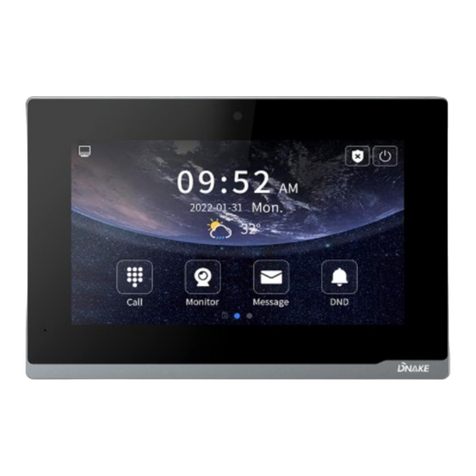
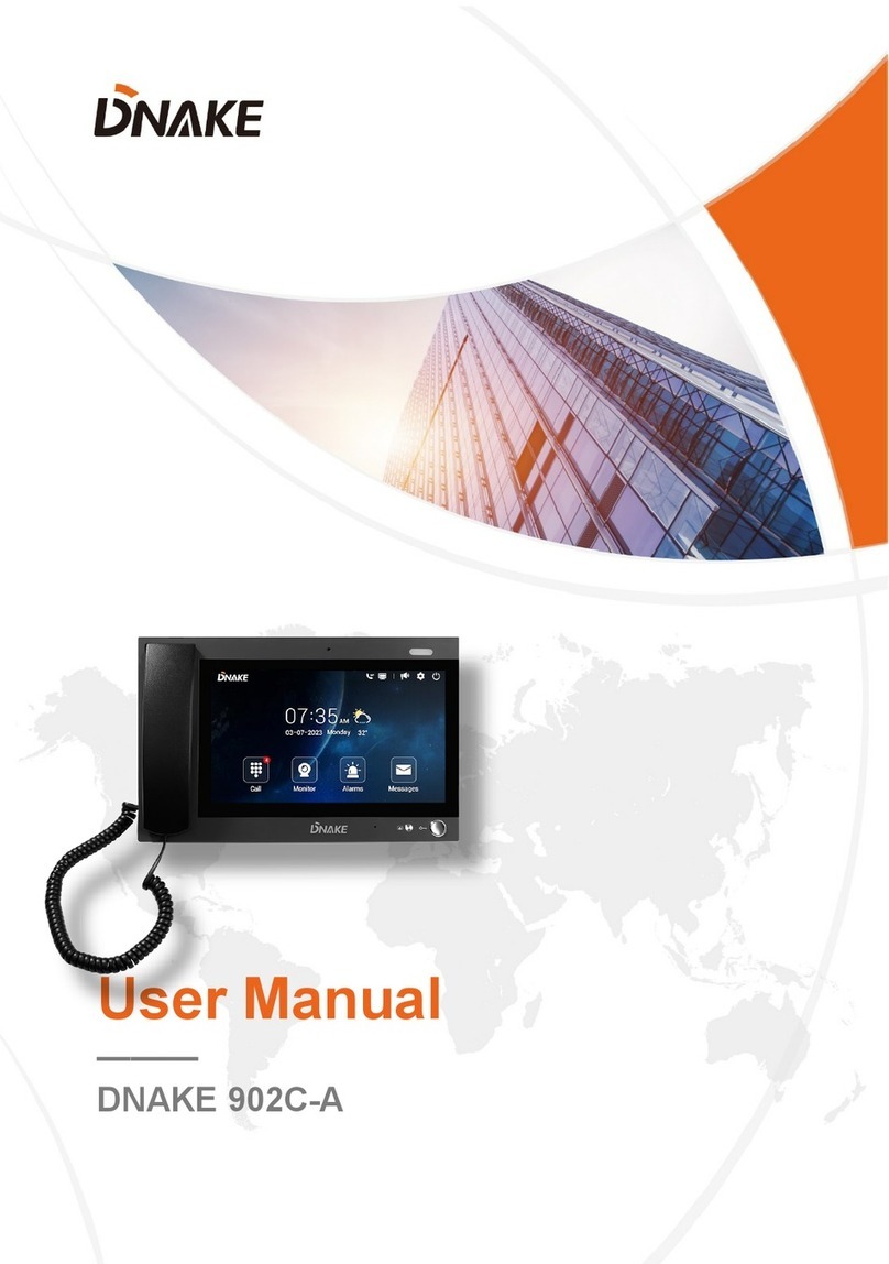
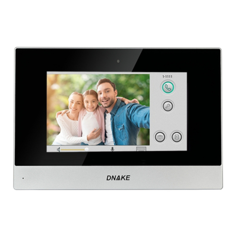
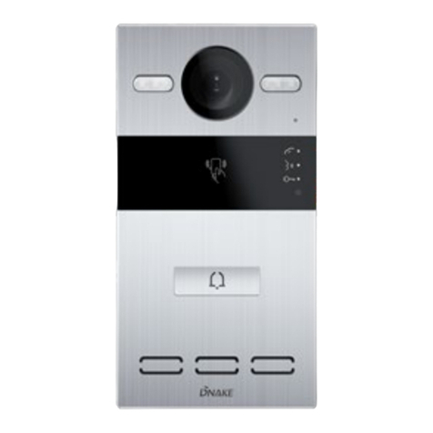
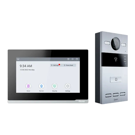
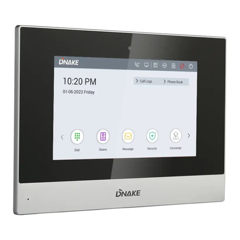
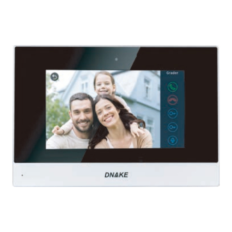
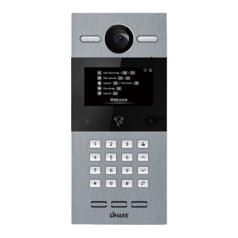
Dnake E211 User manual

User Manual
———
DNAKE E211


REMARK
Please follow the user manual for correct installation and testing. If there is any
doubt please call our tech-supporting and customer center.
Our company applies ourselves to reformation and innovation of our products. No
extra notice for any change. The illustration shown here is only for reference. If
there is any difference, please take the actual product as the standard.
The product and batteries must be handled separately from household waste.
When the product reaches the end of service life and needs to be discarded,
please contact the local administrative department and put it in the designated
collection points in order to avoid the damage to the environment and human
health caused by any disposal. We encourage recycling and reusing the material
resources.

CATALOG
PRODUCT FEATURE ............................................. 1
TECHNICAL PARAMETER ..................................... 1
PACKAGE CONTENT ............................................. 2
OVERVIEW.............................................................. 3
BASIC OPERATION ................................................ 7
WEB SETTING ........................................................ 9
SYSTEM DIAGRAM .............................................. 21
DEVICE WIRING ................................................... 22
INSTALLATION...................................................... 25
TROUBLESHOOTING........................................... 29
SAFETY INSTRUCTION ....................................... 30

1
PRODUCT FEATURE
1. Elegant Design
2. Fade-resistant keys
3. Fully functional
4. Surface mountable
5. Optional handset
6. Optional Wi-Fi
7. Model Description:
E211 (Standard); E211W (Wi-Fi);
E211H (Handset); E211A (Wi-Fi + Handset)
TECHNICAL PARAMETER
System: Linux
Front Panel: Plastic
Power Supply: PoE (802.3af) or DC 12V/2A
Standby Power: 1.5 W
Rated Power: 6 W
Wi-Fi: IEEE802.11 b/g/n,@2.4GHz (Optional)
Ethernet Port: 1 x RJ45, 10/100 Mbps adaptive
Working Temperature: -10℃to +55℃
Storage Temperature: -40℃to +70℃
Working Humidity: 10% to 90% (non-condensing)

2
PACKAGE CONTENT
MODEL: E211/E211W (No handset)
E211 Bracket PM4×20 (2 pcs) Diode (8 pcs) Wires
Quick Start Guide
MODEL: E211H/E211A (With handset)
E211 Bracket PM4×20 (2 pcs) Diode (8 pcs) Wires
Quick Start Guide Handset

3
OVERVIEW

4
Note:
1. DND
Short press to turn on/off do not disturb when on standby and no alarm
detected.
(Backlight will keep on when DND is enabled. No calls can call in and DND on the
device is only for enabling the whole day or disabling. The duration of DND can
only be configured on the web.)
2. Microphone Mute
a. Short press to mute the microphone when talking.
(Backlight will keep on when Mute is enabled. The party on Door Station won’t
hear anything from Indoor Monitor. Indoor Monitor will be unmuted again after the
call is hang up.)
3. Volume Decrease
a. Short press to lower the system volume when ringing or calling;
(System volume will be decreased gradually after every short press.)
b. Short press to lower the call volume when talking;
(Call volume will be decreased gradually after every short press.)
4. Volume Increase
a. Short press to increase the system volume when ringing or calling;
(System volume will be increased gradually after every short press.)
b. Short press to increase the call volume when talking;
(Call volume will be increased gradually after every short press.)
5. Call Master Station/SOS

5
a. Short press to call Master Station;
(Backlight of Answer/Hang up will flash. Ringback tone can be heard.)
b. Long press 2s to send SOS;
(Backlight will keep on for 2s. SOS can be initiated anytime.)
6. Answer/Hang up
a. Short press to answer when ringing;
(Backlight will stop flashing and keep on.)
b. Short press to hang up when talking;
(Backlight will turn from on to off.)
c. Short press to cancel when calling;
(Backlight will stop flashing and turn off.)
d. Short press to call target number when in standby mode (Target number
should be added beforehand);
(Backlight will flash. Ringback tone can be heard.)
7. Unlock
a. Short press once within 2s to unlock relay 1 when talking;
b. Short press twice within 2s to unlock relay 2 when talking;
c. Short press three times within 2s to unlock relay 3 when talking;
(Backlight will flash one time after 2s and lock will start to unlock.)
d. Long press 2s to clear the alarm;
(Security alarm will be turn off while confirming alarm)
8. Volume Increase ( ) + Volume Decrease ( )
Long press and hold “+” and “–” simultaneously to switch ringtones. Press
“+” or “-” to choose; 4 kinds of ringtones available.
(Both backlights will keep on until you long press and hold them again.)

6
9. Microphone Mute ( ) + Volume Increase ( )
Long press and hold “ ” and “+” simultaneously to turn on/off defense.
(Backlight of LED indicator light below will keep flashing. And Indoor Monitor will
make a beep sound.)

7
BASIC OPERATION
1. Get QR Code for DNAKE Smart Life app
Log in the device’s web configuration page with account (user) and password
(1234). Click QR Code and scan by DNAKE Smart Life app to add this Indoor
Monitor to your phone. Only when the license is filled in Internet-connected Indoor
Monitor, QR code will be available.
2. Add More Indoor Monitors
Keep Building, Unit, Apartment No., Sync the same as other Indoor Monitors, and
Device number should be different. The Device number can be from 0 to 9. But
you must have one Indoor Monitor’s Device number is 0 and keep it online
because 0 here stands for the main one.

8
Or go to Indoor Monitor’s webpage and find Ex Phone in Intercom > Call. Users
can directly extend to more Indoor Monitors by filling in sip:IP address (6 Max)
such as sip:192.168.68.90. (Please refer to WEB SETTING for the way to access
to webpage)

9
WEB SETTING
Connect Indoor Monitor and PC to a network switch in the same LAN. You can
enter the IP address of Indoor Monitor in the web browser search bar and log in
with the default account (admin) and password (123456). This is where you can
configure the device.
To get the IP address, you can search by DNAKE Remote Upgrade Tool installed
in the same LAN with the devices.
1. General
1.1. General > Information
When you first log in to the web interface, you can find basic information
displayed in this dashboard.

10
Model:
Model of the device;
Firmware Version:
Firmware version of the device;
MAC Address:
MAC address of the device;
Framework:
Framework of the device;
UI:
UI of the device;
DHCP:
Status of DHCP;
IP Address:
Current IP address of the device;
Mask:
Subnet mask of the device;
Gateway:
Gateway of the device;
DNS:
Domain Name Server of the device;
Account:
SIP account of the device;
Status:
Status of SIP registration of the device;
CMS IP:
IP address of CMS;
Status:
Status of CMS registration;
1.2. General > Basic
Some basic settings of the device can be configured in this column.

11
Language:
16 languages supported (简体中文, English, 繁體
中文, תי ִרב ִﬠ, Deutsch, Español, Türk, Tiếng Việt,
Nederlands, Português, Polski, Русский, ﻲﺑرﻋ,
Français, Italiano, slovenský);
System Vol:
Volume of System can be set from 1 to 6.
Volume 6 is the maximum volume (Key tone);
Intercom Vol:
Volume of Intercom can be set from 1 to 6.
Volume 6 is the maximum volume (Call volume);
Ringtone:
The ringing sound (Ringtone 01-04);
Standby LED Indicator:
The switch for LED light on the device;
Key Tone:
The keytone (Enable or disable);
Auto Answer:
Pick up the phone automatically when receiving
a call;
DND:
Disable or set a time for do not disturb (Disable,
Whole Day, or Duration);
1.3. General > Time
Time of the device can be configured. Daylight Saving Time is also supported.
Auto (Time):
Enable to synchronize computer time;
Date&Time:
Date and time can be set manually;
NTP URL:
Network Time Protocol (NTP) is a protocol used
to synchronize NTP time;
Time Zone:
A region that observes a uniform standard time;
1.4. General > Password

12
The System password is for the administrator to log in settings on the device
while the Web password is for the administrator to log in settings on the web. The
default password for both of them is 123456. User for Indoor Monitor is the
security password whose default password is 1234.
Admin Old Password:
Current administrator password of the web
(Default 123456);
Admin New Password:
New administrator password of the web;
Admin Confirm Password:
Confirm administrator password of the web;
1.5. General > System
The system column is designed for data backup and restore, firmware upgrade,
factory default, device reboot, packet capture, logs capture, and obtaining UI
screenshots.

13
Reset:
Reset to factory settings;
Reboot:
Reboot the device;
2. Intercom
2.1. Intercom > Device
Numbers here are basic settings for making a call to Indoor Monitor. For Door
Station, the building and unit number should be the same as those in Indoor
Monitor.
For Villa Station with one button, the building, unit, and room number should be
the same as those in Indoor Monitor.
When users want to use more than 1 Indoor Monitors, keep Building, Unit,
Apartment No., Sync the same as other Indoor Monitors, and Device number
should be different. The Device number can be from 0 to 9. But you must have
one Indoor Monitor’s Device number is 0 and keep it online because 0 here
stands for the main one.

14
Building:
Number of the building (Range: 1-999);
Unit:
Number of the unit (Range: 0-99);
Room:
Number of the apartment (Range: 0-9899);
Device No:
Number of the device (Range: 0-9);
Sync:
A number used to synchronize to other Indoor
Monitors;
2.2. Intercom > Network
The device network can be set to either DHCP or a static IP address. CMS
parameters should be configured here when you try to register this device to
CMS.

15
DHCP:
Enable DHCP (Dynamic Host Configuration
Protocol) to dynamically distribute network
configuration parameters;
IP Address:
Configure Static IP address to manually
distribute network configuration parameters;
Mask:
Subnet mask;
Gateway:
A component that is part of two networks, which
use different protocols;
DNS:
Domain Name Server of the device;
Wi-Fi:
Search and connect to Wi-Fi to access the
Internet;
CMS:
Enable to use CMS software to manage devices;
CMS IP:
Server address of CMS;
2.3. Intercom > SIP
The SIP column concerns SIP registration, Display Name, Register Name,
Username, Password, SIP Server Host, Outbound Proxy, Transport Protocol,
Video Payload, etc.
SIP:
Enable to use SIP;
Display Name:
Display name of SIP account;
Register Name:
Register Name of SIP account;
Username:
Username of SIP account;
Password:
Password of SIP account;
SIP Server Host:
SIP Server domain or IP address; the default
port is 5060;

16
Outbound Proxy:
Outbound Proxy server; the default port is 5060;
Transport Protocol:
Transport Protocol (UDP, TCP, TLS);
Video Payload:
Video payload range is 96-127;
2.4. Intercom > Call
Ring group is for setting up SIP calls or call mode. Concierge button, extension of
other Indoor Monitors, the length of the call, and ring time can also be configured
here.
Call Concierge URL:
Fill in any device’s IP address. The concierge
icon or button will be directed to this destination;
Target Number:
Fill in other device’s IP address. Call button on
the device will be related to this target number.
Ex Phone:
Extend to more Indoor Monitors by filling in sip:IP
address (6 Max) such as sip:192.168.68.90 (6
Max);
Ring Time:
The ring will be ended automatically after a
period of time (10s, 20s, 35s, 45s, 60s, 90s,
120s)
Call Time:
The call will be ended automatically after a
period of time (120s, 300s, 600s, 1200s, 1800s);
2.5. Intercom > Call Logs
All call logs can be checked here.
Other manuals for E211
1
Table of contents
Other Dnake Intercom System manuals