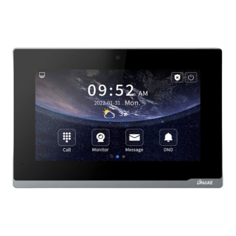
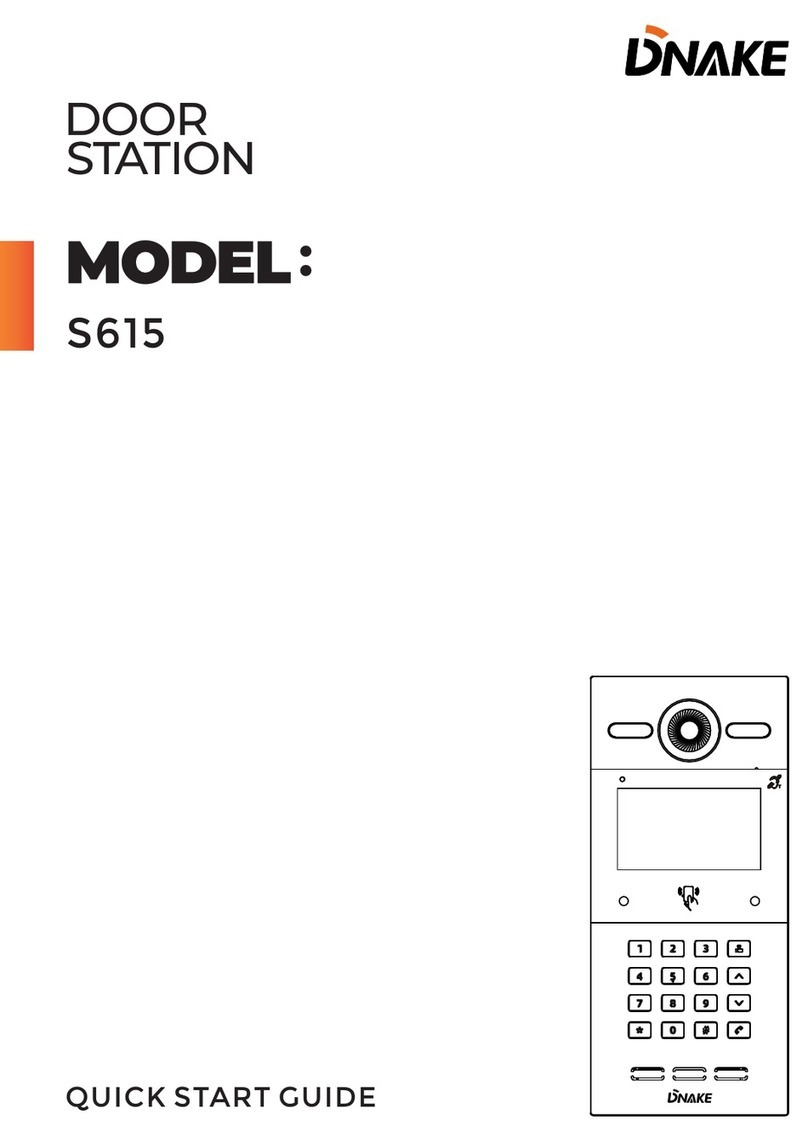
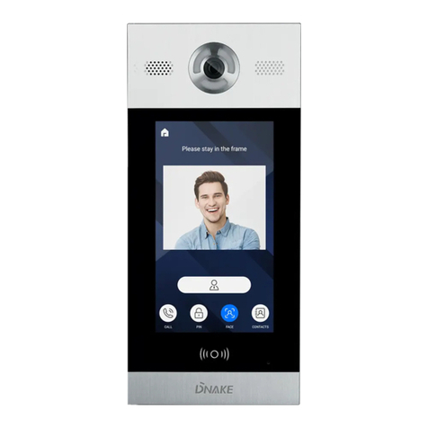
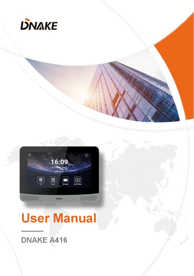
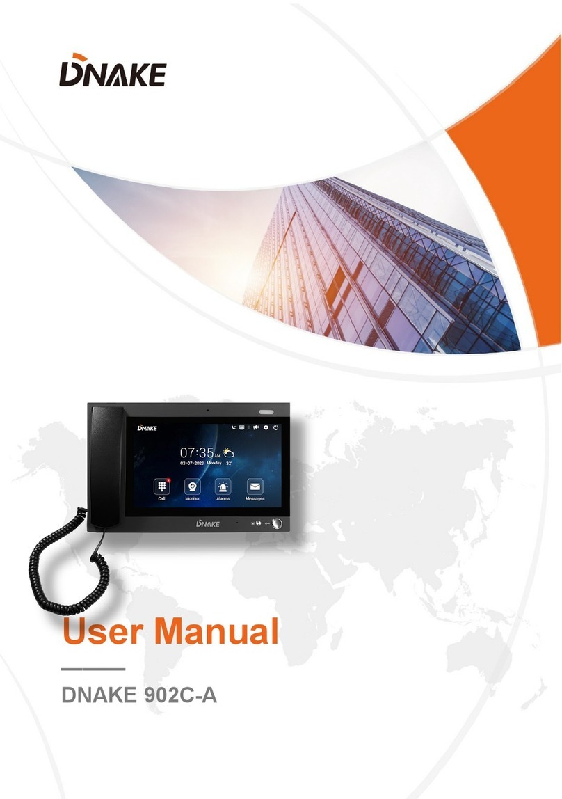
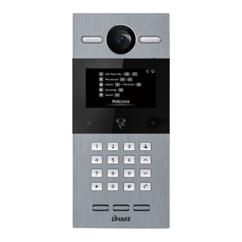
Dnake 902M S8 User manual

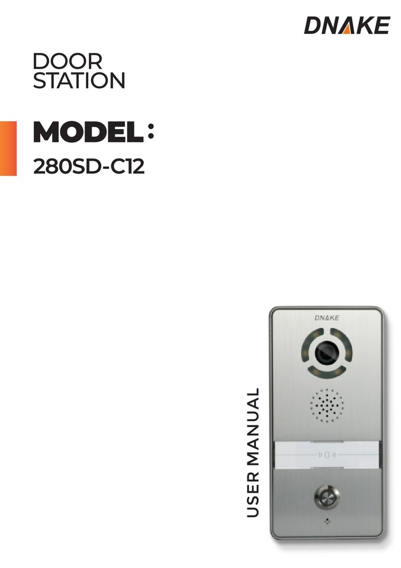
Model: 280SD-C12
280SD-R2
280SD-R5
Quick Start Quide
Door Station
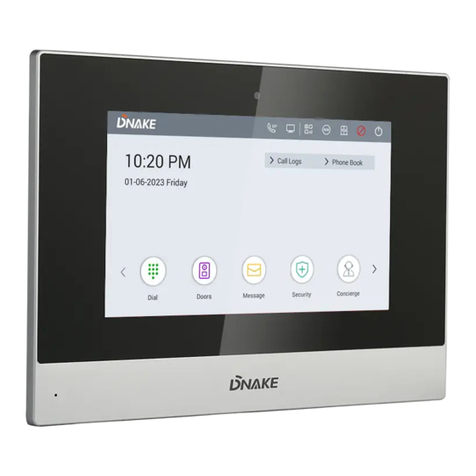
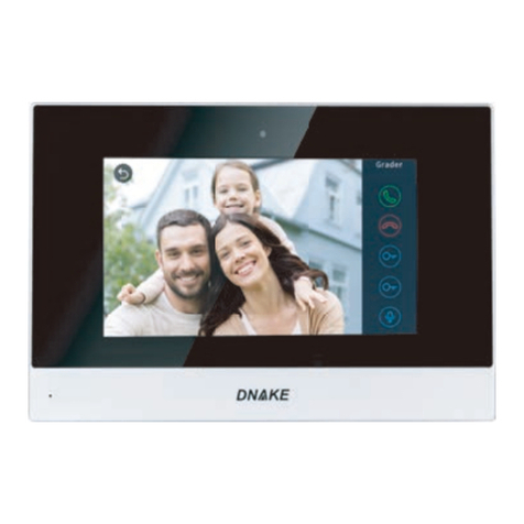
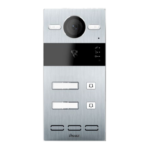
The picture is only a schematic diagram. The actual product shall prevail.
902M S8
USER MANUAL

Please follow the user manual for correct installation and
testing. If there is any doubt please call our tech-supporting
and customer center.
Our company applies ourselves to reformation and
innovation of our products. No extra notice for any change.
The illustration shown here is only for reference. If there is
any difference, please take the actual product as the
standard.
The product and batteries must be handled separately from
household waste. When the product reaches the end of
service life and needs to be discarded, please contact the
local administrative department and put it in the designated
collection points in order to avoid the damage to the
environment and human health caused by any disposal. We
encourage recycling and reusing the material resources.
REMARK

CATALOG
Product Features......................................................1
Technical Parameters...............................................1
Package Contents ....................................................2
Pictures.....................................................................2
Operations................................................................3
1. VOIP......................................................................4
2. Security...............................................................11
3. Smart ..................................................................16
4. Service................................................................20
5. About 902 ...........................................................21
Web Settings ..........................................................22
System Configuration ............................................26
System Diagram.....................................................27
Installation..............................................................29
Troubleshooting .....................................................30
Safety Instructions .................................................31

PRODUCT FEATURES
TECHNICAL PARAMETERS
Voltage: DC 12V
POE
Rated power: 9W
Standby power consumption: 1.5W
Display screen: 7''
Touch screen: Capacitive touch screen
Resolution: 800x480
Working Temperature: -10℃ to +55℃
Storage Temperature: -10℃ to +60℃
Working Humidity: 10% to 90% (non-condensing)
1
1. Building intercom application:
VOIP: Support video call, monitoring, unlocking, VOIP
communication and call record checking.
Security: Support 8 alarm zones with 3 states, alarm zone and
scene setup.
Smart: Support smart home extension by RS485 communication.
Others: Support Android systems applications.
Voltage: DC 12V
POE
Rated power: 10W
Standby power consumption: 3W
Display screen: 7''
Touch screen: capacitive touch screen
Resolution: 1024X600
Working Temperature: -10℃ to +55℃
Storage Temperature: -10℃ to +60℃
Working Humidity: 10% to 90% (non-condensing)
RAM: 1GB
ROM: 4GB

Package Contents
Quick Start Guide
Indoor Monitor
MODEL: 902M-S8
Please make sure the package contains the following items:
Screw
PACKAGE CONTENTS
2
PICTURES
Microphone
7'' capacitive
touch screen
Speaker

3
OPERATIONS
Main menu: VOIP, Security, Smart, Service, Contacts, Calendar, Mediaplayer
and About 902.
Shortcut key: Elevator, Out, Unlock and Apps.
1.The main interface will remind user when there are missed calls, unread
MSG and SMS.
2. The state of weather is synchronously updated by NTP.
Status bar: Return, Main interface, Background program, Volume-,Volume+.
When the user enters into secondary menu, the interface displays the
following icons at the bottom of the screen.
Status bar instruction:
1. Return :Click it to return to previous menu.
2. Main interface : Click it to return to main interface.
3. Background program : Click it to display the operating program
running in the background.
5. Volume- : Click it to reduce the volume.
6. Volume+ : Click it to increase the volume.

4
Clicking “VOIP” icon on the main interface, the system will enter the
following interface:
1.1 Call
Clicking “Call” icon, the system will enter the following interface:
1.VOIP
1.1.1 Call unit resident
Input 1-3 digits building No.+ “Building” + 2-digit Unit No. + “Unit” +4-digit
room No., then click icon to call.
The system will enter into the following interface:

5
When the call is answered, the system will enter into call state:
1. If there is a camera, the caller’s image will be displayed on the screen;
2. When the call is answered, the video will be uploaded into the indoor
monitor.
When the door station, wall panel or secondary door station calls, the
indoor monitor will ring; when door station calls indoor monitor, the image
from door station will be displayed on the indoor monitor; if there is no
answer within 25 seconds, the call will be ended.
Click icon to communicate with door station; click icon to end the
call; click icon to unlock the door.
Remark: visual intercom function between households is optional.
You can make audio and video recording during communication (TF card
should be inserted into indoor monitor ). Click icon to take a snapshot of
the visitor; click icon to save the video and image for current
communication.
The system’s default call duration is 120s.
1.1.2 Call management center
Clicking “Center” icon to call management center(namely master
station), the system will call management center No.1-No.5 successively. If
the management center cannot be searched or call failed, the system will
automatically call next management center. When the management center
answers, it will ring and stop calling next one.
Click icon to end the communication.

6
1.2 Monitor
Clicking “Monitor” icon, the system will enter the following interface:
Click “Door01” icon to switch the type of door station, then click or icon
to select the area you want to monitor, and click icon to monitor the
door station or secondary door station. Click icon to end monitoring.
Click icon to unlock the door.
Remark: The system’s default monitoring time is 25s.
1.3 Records
Clicking “Records” icon, the system will enter the following interface:

7
refers to call-out record; refers to call-in record; refers to missed
call record. It can save up to 64 records.
Click or icon to search for records. Select one record and click icon
to call; click icon to delete it. Click icon to back-up.
If there is snapshot image, click icon to view it.
1.4 Room
Click “Room” icon, then input 1-16 digits password (the default password is
123456 ) to enter into the following interface:
Warning: Please revise synchronous No.(6 digits) as soon as possible after
you read the user manual. The synchronous No. of all indoor monitors in
one household must be the same.
Input the 3-digit Building No. such as 001, and then click “OK” to finish the
building No. setting.
The setting method of Unit No.,Floor No., Room No., Device No. and
Synchronous No. is the same as the one of Building No.. The Unit No., Floor
No. and Room No. are limited to 2 digits respectively. When Device No. is
set to be 0, the indoor monitor is regarded as the main; when Device No. is
set from 1 to 5, as the sub1 to sub5.

8
1.5 VOIP
Clicking “VOIP” icon, the system will enter the following interface:
Proxy: URL of sip proxy server, format in sip: ip or sip: realm name.
Realm: the scope for the device, is the same with IP or realm name.
Password: the password to access proxy server, offered by the administrator of
sip proxy server.
Stun IP and Port: the public network server IP and port crossed by audio/video
NAT.
To connect with SIP phone, check “Enable” and input the registered SIP
account.
1.6 Settings
Clicking “Settings” icon, the system will enter the following interface:

9
1.6.1 Intercom
Check “Camera” , “Message” or “Auto answer” to enable corresponding
function, then click “OK” icon.
1.6.2 Network
Click “Network” icon to enter into the following interface:
After using the , the router will automatically distribute IP address. DHCP
Other settings are the same as the ones of intercom APP.
Sys IP: the system will automatically display IP address of the indoor
monitor.
IP: IP address is unique.
Mask: The default Mask address is 255.255.255.0. Normally, it is unnecessary to
modify. If you would like to modify it, clicking the setting box twice, a keypad
will pop up. Enter your new Mask address.
Gateway: The Gateway in one system must be in the same segment.
DNS: domain name resolution address (DNS of local operator). If the indoor
monitor is used in external network, the address must be completed
correctly; if it is used in internal network, the address can be ignored.)
Click “OK” to save the settings.
Remark: the settings should be made after inputting password to enter into
room No. settings.

10
1.6.3 Password
Clicking “Password” icon to enter into the following interface:
You can set the new system password with 1-16 digits (the default
password is 123456). System password is used for system settings.
Scanning the QR code with DNAKE smart life APP, it will be synchronized
with the indoor monitor.
1.6.4 QR Code
Click “QR Code” icon to enter into the following interface:

11
Clicking “Security” icon on the main interface, the system will enter into
the following interface:
2.Security
2.1 ON/OFF
Clicking “ON/OFF” icon, the system will enter into the following interface:
2.1.1 ON
Clicking “Out”, “Home”, or “Sleep” icon to activate the alarm sensors, the
icon on the main interface will light with a beep and this icon will always
light up.
2.1.2 OFF
(1) During the alarm delay time, clicking “OFF” icon, the system will give a
tone, then the alarm is disabled.
(2) Input user password(the default password is 1234) to disable the alarm
under alarm ON status.

12
2.2.1 IP Camera Setting
Login the webpage of indoor monitor by username: user, password:1234,
then you can access the following webpage:
2.2 Camera
Clicking “Camera” icon, the system will enter into the following interface:
Click “ ” or “ ” button to select the camera, and then click to monitor the
IP camera. During monitoring, to cancel monitoring, click to stop it.

13
Clicking “Camera” icon, the system will enter into the following
Click “ ” or “ ” button to select IP Camera to monitor, and then click
icon to monitor. Click to stop monitoring.
Fill in with the RTSP format: rtsp:// user: password@ Camera IP. IP is the IP
address of your IP Camera.Then you can monitor IP Camera in Security
menu on your indoor monitor:
2.3 Zone
Remark: the settings should be made when alarm is OFF.
Clicking “Zone” icon and inputting 1-16 digits password(the default
password is 1234), the system will enter into the following interface:

14
2.3.2 Mode
Clicking mode setting box, it will pop up a dialog box as the following
interface. In this interface, you can set mode as: 3C, NO, NC or BELL.
2.3.1 Alarm Type
Clicking type input box, it will pop up a dialog box as the following. In
this interface, you can set alarm Type as: Normal, Emergency or 24H. 24H
and Emergency type are always active.

15
2.3.4 Sensor Type
Clicking sensor type input box, it will pop up a dialog box as the following
interface. Each sensor type can be set up as: Smoke, Gas, PIR, Door,
Window, Panic, Flood, Pull Cord or Bed Mat.
2.3.3 Delay Time
It refers to the delay time of giving an alarm. Clicking Delay setting box, it
will pop up a dialog box as the following interface with selections: 0s, 5s,
15s, 20s, 25s, 40s or 60s as the desired delay time. For example, select the
delay time: 5s. Once the alarm sensor is triggered, 5 seconds later, the
indoor monitor will sound sirens.

16
You can see the No. and sensor type in red showed at the top of interface.
For example: “1:Smoke” indicates that in Zone 1 Smoke sensor is triggered.
To stop the alarm sound, input the password (the default password is 1234).
When alarm sensor is triggered, the indoor monitor will make a loud alarm
sound. The system will enter into the following interface and send alarm
message to master station(if your system is installed with management
center):

17
2.4 Scene
Clicking “Scene” icon, the system will enter into the following
refers to Alarm ON, refers to Alarm OFF. To set the sensor of alarm
stations, you can click the corresponding station with icon. Click
"Activation Time" to choose the corresponding time. The options of
activation time include NONE, 30s, 40s, 60s, 100s and 300s.
You can set the new user password with 1-16 digits (the default password is
1234). User password is used for security.
2.5 Settings
Clicking “Settings” icon, the system will enter into the following interface:
Table of contents
Other Dnake Intercom System manuals